@Wuerfel_21 said:
Kind of obnoxious that all the high density parts (> 16 Mbit per bus pin) are 1.8V only. Has anyone tried if interfacing these really is a lost cause?
@hinv said:
Did we switch away because of the expense of these? Wasn't the HyperRam faster?
HyperRam is faster for the same number of pins, as it uses DDR, while the PSRAM (that we are using) is SDR clocked.
However PSRAM has the advantage of letting the P2 have twice as many sampling opportunities to read the data reliably, making the timing a little easier to control. To mostly compensate for the reduced speed we do get twice the data width on the P2-EC32MB (16b instead of 8b), at the expense of 7 more pins being needed (or 6 if you wire the RESET pin on HyperRAM).
Also the trend for price is that PSRAM is cheaper. In low to medium quantities Digikey is selling 64Mbit HyperRAMs for ~$8 (1.8V), and 128Mbit parts for ~$11 but you can pickup the new octal 128Mbit PSRAMs for around $4.60 at Mouser (at 3V). That Digikey linked stuff is kinda moot though for the P2 use because they are 1.8V parts.
In theory if the CLK, data bus and DQ pins can handle the parallel load you could make a 6 bank setup (96MB) with two 8 bit breakout connectors on P2-EVAL with this new PSRAM OPI memory.
8 data bus pins
1 CLK
1 DQS/DM (tri-state & shared)
6 CE pins (1 per device)
With so much bandwidth and DDR operation you could probably afford to halve the clock anyway if the load was a issue.
@rogloh said:
In theory if the CLK, data bus and DQ pins can handle the parallel load you could make a 6 bank setup (96MB) with two 8 bit breakout connectors on P2-EVAL with this new PSRAM OPI memory.
8 data bus pins
1 CLK
1 DQS/DM (tri-state & shared)
6 CE pins (1 per device)
With so much bandwidth and DDR operation you could probably afford to halve the clock anyway if the load was a issue.
Unfortunatelly, pin capacitance data and maximum drive strength for the 3V 128Mb OPI Xccela Psrams seems to be almost the same as the ones given by the 4-bit Psrams we're using:
Drive strength is programmable, at least, but it only enables derating, from 50Ohm down to 100/200/400Ohm, which suggests they can be "tunned" to behave as low-noise as possible "whispering at controller's ears???), in order to avoid most part of the reflections (if any, at all), when the chip is almost "tacked" to the driving controller. Sure, not the intended use-case...
P.S. It realy apears they're never meant to be part of any meaningfull "multiple-device-bus-concept".
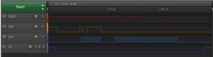
In some test code below I was able to get some asymmetric clock pulses generated at sysclk/3 and the PSRAM address output from the streamer at sysclk/3 with the rising edge of the clock located 2/3 of the way into the data bit width. It could also be put 1/3 of the way in.
I'm going to try to merge this in with an experimental/hacked 4 bit driver to see if my memory delay test can work with Rayman's 96MB board operating at sysclk/3 more reliably at higher P2 clock speeds. I'll probably keep the writes at sysclk/2 for now in this test. Although the clock mode will need to be adjusted there too, so maybe that has to change anyway.
Since write and read commands need to be terminated by a high-going CE#, while CK = "Low", maybe you'll need to ensure an extra P2_Sysclk of "resting-period" at CK = "Low", before effectivelly pulling CE# High, as to ensure enough time, either for P2 and/or PSRam to "capture" data with some advisable margin.
Can't seem to get divide by 3 clocks working with the PSRAM... it might just not like the asymmetric clock. Will probably have to split writes and reads fully to check this out because the writes are also now using these 1:3 duty cycle clocks.
UPDATE: with reads set back to sysclk/2 and writes at sysclk/3 it fails.
UPDATE2: with reads at sysclk/3 and writes at sysclk/2 it fails, even down at 100MHz. Found a bug, now I can write at sysclk/2 and read at sysclk/3...still checking this.
Fixed the bugs and have both reads and writes running at sysclk/3 now with this experimental 4 bit driver.
In theory if I port this to the 16 bit driver I can run my 16 bit PSRAM video demo at 1024x768x8bpp with a P2 clock of 325MHz (pixel clock = 65MHz) and the PSRAM memory is being read at around 108MHz which is within its rating of 133MHz (otherwise it's overclocked to 162.5MHz).
I think you wanted something like this too @pik33 if I recall correctly because some of your PSRAM couldn't quite reach the high frequency you needed.
The low level drivers do support multiple devices and buses, and have from the start. This is really the first time we are trying it out in anger with Wuerfel's code, and an initialization bug was fixed there recently that was only initializing a single PSRAM bank. There is the original high level "memory" driver in SPIN2 that is more complex to use but should support multiple disparate bus types, and there are some simpler "wrapper" drivers which were intended to be a much easier way to get something working with just a single device. These wrappers now are sort of evolving to try to support multiple banks on the same bus, but by doing that it increases its complexity. I'm trying to rationalize it all, but it's not simple any more.
I'm trying an experiment to see if I can (just) squeeze in SPI FLASH access into my PSRAM driver.
Right now there are 13 longs free in LUTRAM and 2 in COG RAM in my 16 bit PSRAM driver but if I replace the fast EXECF table lookup scheme I use, I found I can free just over 100 longs in COG RAM. The cost for this about 4-5 extra instructions of latency per request using a different lookup scheme so it's probably still worth it in many cases. The benefit here is that you can get the 16MB of P2 boot flash mapped into the external address space and if you are using the PSRAM driver already you will not need another COG for this. It will support all the normal byte/word/long/burst reads, request lists, and regular/graphics copies (as a source device, not a destination), so you could put code/data/graphics into FLASH and them copy them into PSRAM or HUB as needed with a simple transfer command, or just read the data directly from FLASH on demand by any COG. This should work even while video sourced from PSRAM frame buffers is actively used too.
I'm trying to get dual SPI mode integrated as well for reads to allow 33MB/s of read burst bandwidth at full flash speed (maybe higher if it's overclockable). Writes will use the register access mode (SPI only), along with R/W access to other internal flash registers, for erasing sectors etc. While writing to FLASH, access to all FLASH reads will be blocked, but PSRAM reads/writes can still occur in parallel.
This experimental driver will look a bit like my HyperRAM/HyperFlash combo driver, but will support PSRAM/SPI FLASH instead.
If this extra SPI FLASH code can be made to fit within the footprint of my 16bit PSRAM driver, it will work in 8/4 bit drivers as well, and could be ported there too later. 16bit PSRAM is the biggest driver of all of them.
This SPI FLASH + PSRAM combo code is agonizingly tight to fit. But I think I might squeeze it in if I use a slight hack where the commented out code below that doesn't fit is instead is run from HUBEXEC before switching back to COG ... and if the skipf sequence I need for the RDFAST/WRFAST selection survives a nested call. If not I might have to duplicate more code in HUB. I don't like running much from HUBEXEC as it makes the driver a little more fragile to memory corruption from any wayward COGs but this is just register access code needed during flash writes and not the main flash read request code which still fits inside the COG.
Right now I'm at 5 free COG RAM locations and 2 LUT RAM locations with I think is what is needed inside the COG+LUT. I'll probably need those extra COG RAM locations so I can make the streamer and clock timing independent for PSRAM and FLASH.
But this is good news I guess, we can hopefully get access to both SPI FLASH + PSRAM in the same driver and address space once it's debugged and working...
reg_write
reg_read
call #setuprw
{{
setnib id, addr1, #0 'get the COG id making the request
getnib b, addr1, #6 'get bank
rdlut b, b wz 'read bank info
if_z jmp #invalidbank 'if not data, exit with error
setq #1 'write two longs
wrlong #0, ptrb 'clear mailbox results initially
call #\checkflash_w 'check flash access to reads/writes
getnib delay, b, #3 'get delay timing
shr delay, #1 wc 'extract delay field
bitnc regdatabus, #16 'setup registered/unregistered
getbyte cmdaddr, addr1, #3 'get command byte
mov wrclks, #8 'setup clks for command byte
getnib d, addr1, #1 'get # of addr bytes to write
mul d, #8 wz 'scale and check for zero
modc $5 'c=z
setword xaddr1, d, #0 'address byte length
add wrclks, d 'include these clocks
getnib d, addr1, #2 'get # of data bytes to write
rolbyte d, hubdata, #3 'include hubdata bytes
mul d, #8 wz 'scale and check for zero
setword xdata1, d, #0 'data byte length
add wrclks, d 'include these clocks
getnib d, addr1, #3 'get # of data bytes to read
fle d, #8 'no more than 8 bytes of result fit the mailbox
mul d, #8 'convert to SPI clocks
setword xrecvdata1, d, #0 'zero clocks does a transfer?
_ret_ add wrclks, d 'final wrclks tally
}}
wrfast xfreq1, ptrb
rdfast xfreq1, ptrb
wxpin #1, #FLASH_CLK_PIN
drvl #FLASH_CS_PIN
drvl #FLASH_DI_PIN 'drive out data bus pins to DI input
wxpin clkduty, #FLASH_CLK_PIN
push #notify
xinit xcmd, cmdaddr 'send command byte
wypin clks, #FLASH_CLK_PIN 'start clocks
if_z xcont xaddr1, count 'send address
if_c xcont xdata1, data 'send data
setq xfreq1 'move to sysclk/1
add clkdelay, delay 'includes time for pipeline delay + iodelay
xcont clkdelay, #0 'delay
sub clkdelay, delay 'restore for next time
waitxmt 'wait for data to be sent before tri-stating
fltl #FLASH_DATA_PIN 'tri-state data bus
wrpin regdatabus, #FLASH_DI_PIN 'selected registered/unregistered data pins
setq xfreq2
xcont xrecvdata1, ptrb 'read back bytes to mailbox (up to 64 bits)
waitxfi
wrpin registered, #FLASH_DI_PIN 'restore registered data pins
_ret_ drvh cspin
@Rayman said:
Does this driver support the 8-bit, hyperram like, psram chips?
Not yet, I don't have any of those parts to try. Given how similar it is to the Hyper bus signaling protocol I'm thinking with any luck I could go modify my existing HyperRAM driver to suit. And I'd probably be able to remove the HyperFlash support inside it if more space is needed and add in SPI flash instead, which is handy.
Rayman,
Do you already have an add-on board with these OPI chips? It should be easy to tweak my tester. Have to throw away the 16 entry Command-Address duplicating LUT. Make it an 8-bit version of the older 1x4-bit-only code.
EDIT: Notably, OPI parts don't have any SPI fallback mode. Should make things easier.
Far out this COG is tight! I've just added the last touches and support for independent sysclk timing for both Flash and PSRAM, as well as unregistered/registered input selection. Because the Dual IO pin read mode I use needs a remap in the Smartpin input stage to fix the DO/DI wiring problem on the P2, that multiplies the COGRAM use by 2 for this feature and I have to store 2 different combinations of Smartpin modes for each of these pins and select between them dynamically. This alone burned up all my COG RAM optimizations and finding spare COGRAM is becoming slim pickings now.
Result: No COG RAM left anymore , and 1 LUTRAM location left (which should increase to 3 once I add pik33's locked list feature).
I really hope there are no bugs that need new instructions or missing lines of code...
Also, it has occurred to me that it would be handy to be able to disable the SPI flash pins dynamically with an API so you can still use the SD card if/when you need to, otherwise this driver COG while running will prevent the SD pins from being controlled, by driving CS high and pulling CLK low while idle. I can probably still do that in HUB exec during my register setup check code that runs there now and just disable access to the flash in the code and float the pins, until another command re-enables it. It sort of needs some co-ordination on the SD card driver side too, to do the same.
EDIT: just found another decent rearrangement that yields 3 more COGRAM longs, so I have some breathing room again. It's nice to have some space for some DEBUG instructions in case I need to track down any bugs. Code is done now, will probably start testing tomorrow.
SPI FLASH + PSRAM driver is alive. Running at 4MHz anyway so I can see what is going on.
I found I needed to gap the clock on register reads, as the P2 streamer can't appear to do zero bus turnaround at slow clock speeds. No matter, the Winbond data sheet allows it, and it's only for register reads like the status register read during FLASH writes etc. Normal data reads with dual SPI have a dummy portion of 4 clocks which is enough to turnaround without gapping the clock (like we do with the PSRAM/HyperRAM latency interval).
JEDEC ID read:
I dumped the SFDP table and JEDEC ID and it seems to match sane expected values of their signatures. Also whatever I had in the SPI FLASH from before (some loader?) seems to be showing up like P2 code would at first glance (eg. the top nibble is $F in most 32 bit P2 opcodes).
I'll need to add the commands to erase and write a page etc to test it more, and try higher speeds. But the basics seem okay for now which is good. Only had about 3-4 bugs, mostly simple errors with constants, not too bad to track down.
@rogloh said:
I found I needed to gap the clock on register reads, as the P2 streamer can't appear to do zero bus turnaround at slow clock speeds.
It should be able to seamlessly join them without pausing the clock. The receiving XINIT has spare sysclocks after a turnaround where the incoming data is shifting through the Prop2's I/O staging buffers.
EDIT: Here's the QPI (for the PSRAMs) turnaround snippet I have:
waitx #8 * CLK_DIV - 5 + TX_ALIGN
dirl datp ' tristate the databus upon CA completion
wrpin rxreg, datp 'set/unset registration during Fast Read's fetch delay
waitx delay ' align streamer timing with incoming rx data
xinit m_dat, #0 ' rx data to FIFO
And delay is built from delay := DELAY_FREAD4 * CLK_DIV - 2 + RX_ALIGN + io_delay ' RAM fetch latency + frequency dependent I/O latency
DELAY_FREAD4 would be zero for register reads. io_delay can be zero too. That leaves RX_ALIGN - 2 as the minimum. RX_ALIGN = CLK_DIV + RX_REGD + TX_REGD Given that CLK_DIV is minimum of two, means the WAITX can be as low as zero itself.
Enough room for three instructions after the DIRL. Everything fits.
EDIT2: Though, a registration switchover won't suit zero latency because the rx pin sampling of first data happens before the WRPIN instruction takes effect ... maybe I could experiment with moving it to the leading side of the tri-stating ...
I could only get it to within a bit clock or two, but not spot on. Maybe there is a way, but I've not figured it out yet. I was using the waitxmt method to wait to tri-state, but that was too slow so I got rid of it and gapped the clock instead.
This was my approach I used to save COGRAM space below. I still need to make the delay programmable instead of hardcoding to 5, but that can be computed in HUB-EXEC.
' SPI FLASH register access
reg_write
reg_read
call #setuprw 'initialize from HUB exec to save space
if_c rdfast bit31, hubdata 'data writes sourced from hub
if_nc wrfast bit31, ptrb 'data reads go to mailbox
wxpin clkdutyflash, #FLASH_CLK_PIN
skipf pattern ' R W (a) register read
' E R (b) register write
' A I
' D T
' E
'
xinit xcmd, cmdaddr ' a b send command byte
wypin wrclks, #FLASH_CLK_PIN ' a b start clock output
xcont xaddr1, count ' ? ? optionally send address/immediate data
xcont xdata1, hubdata ' ? ? optionally send data from hub
waitxfi ' a b wait until transmit phase is over
fltl #FLASH_DATA_PINS ' a b tri-state data bus
if_z wrpin unreg_di, #FLASH_DI_PIN ' a | selected registered/unregistered data pins
xinit #5, #0 ' a | delay
wypin clks, #FLASH_CLK_PIN ' a | start clock output
xcont xrecvdata1, ptrb ' a | read back bytes to mailbox (up to 64 bits)
jmp #wait_to_complete ' a | save repeating some duplicated instructions
jmp #wait_to_complete+1 ' b save repeating some duplicated instructions
....snip...
wait_to_complete waitxfi
wrpin reg_do, #FLASH_DO_PIN 'restore to registered pins
wrpin reg_di, #FLASH_DI_PIN 'restore to registered pin
setxfrq xfreq2 'restore streamer frequency for PSRAM
_ret_ drvh #FLASH_CS_PIN 'disable CS pin and return
'HUB EXEC code follows
' code to setup a read or write of the SPI flash registers or programming its page memory
setuprw
setnib id, addr1, #0 'get the COG id making the request
getnib b, addr1, #6 'get bank
rdlut b, b wz 'read bank info
if_z jmp #invalidbank 'if not data, exit with error
setq #1 'write two longs
wrlong #0, ptrb 'clear mailbox results initially
call #checkflash_w 'check flash access to reads/writes
mov pattern, #0 'setup default pattern
getnib delay, b, #3 'get delay timing
shr delay, #1 wc 'extract delay field
bitnc regdatabus, #16 'setup registered/unregistered
testb addr1, #30 wc 'test read(0)/write(1)
if_c mov pattern, ##%11111000000
getbyte cmdaddr, addr1, #2 'get command byte
mov wrclks, #8 'setup clks for command byte
getnib d, addr1, #1 'get number of addr bytes to write
mul d, #8 wz 'scale and check for zero
bitz pattern, #2 'skip streamer command if zero
setword xaddr1, d, #0 'address byte length
add wrclks, d 'include these clocks
' cmp wrclks, #8 wz
' if_c_and_z or pattern, #$60
getnib d, addr1, #2 'get number of data bytes to write
rolbyte d, hubdata, #3 'include hubdata bytes
mul d, #8 wz 'scale and check for zero
bitz pattern, #3 'skip streamer data if zero
setword xdata1, d, #0 'data byte length
add wrclks, d 'include these clocks
getnib d, addr1, #3 'get number of data bytes to read
fle d, #8 'no more than 8 bytes of result fit the mailbox
mul d, #8 'convert to SPI clocks
setword xrecvdata1, d, #0 'zero clocks does a transfer?
'if_nc add wrclks, d 'final wrclks tally
if_nc mov clks, d 'final wrclks tally
setxfrq xfreq2flash 'setup NCO for streamer
test regdatabus wz 'determine if unregistered
wxpin #1, #FLASH_CLK_PIN 'setup clock rate
drvl #FLASH_CS_PIN 'drive CS low
drvl #FLASH_DI_PIN 'drive out data bus pins to DI input
_ret_ push #notify 'continue from COG RAM
Yeah I used to do that too until I simplified the code and used the waitxmt method (not waitxfi). That was how Ada did it and I preferred reading the code using it. However if you carefully compute the clocks like you do perhaps something can be done with the original waitx method I had. I'm doing it in HUB exec now so there are lots of free instructions to compute this stuff, just not a lot of COGRAM to hold state. The extra overhead will delay the register accesses a little but that's okay.


Comments
@hinv said:
Well, I just noticed that the 3216MB parts are 1.8V...just the overview teased to be 3V
Digikey has
https://www.digikey.com/en/products/filter/memory/774?s=N4IgTCBcDaIMoHYAMBpOBGMAOCBdAvkA
Did we switch away because of the expense of these? Wasn't the HyperRam faster?
EDIT: I thought I fixed my math, this time for sure...
Note that all these are given in MBit. 32Mbit is 4Mbyte
There are 128Mbit parts, so I corrected my bad math after I quoted myself. Doh!
That brings up a good question. Why, in your menu did you give Mbit instead of MByte?
Because that's what they used to print on the game boxes
HyperRam is faster for the same number of pins, as it uses DDR, while the PSRAM (that we are using) is SDR clocked.
However PSRAM has the advantage of letting the P2 have twice as many sampling opportunities to read the data reliably, making the timing a little easier to control. To mostly compensate for the reduced speed we do get twice the data width on the P2-EC32MB (16b instead of 8b), at the expense of 7 more pins being needed (or 6 if you wire the RESET pin on HyperRAM).
Also the trend for price is that PSRAM is cheaper. In low to medium quantities Digikey is selling 64Mbit HyperRAMs for ~$8 (1.8V), and 128Mbit parts for ~$11 but you can pickup the new octal 128Mbit PSRAMs for around $4.60 at Mouser (at 3V). That Digikey linked stuff is kinda moot though for the P2 use because they are 1.8V parts.
In theory if the CLK, data bus and DQ pins can handle the parallel load you could make a 6 bank setup (96MB) with two 8 bit breakout connectors on P2-EVAL with this new PSRAM OPI memory.
With so much bandwidth and DDR operation you could probably afford to halve the clock anyway if the load was a issue.
Unfortunatelly, pin capacitance data and maximum drive strength for the 3V 128Mb OPI Xccela Psrams seems to be almost the same as the ones given by the 4-bit Psrams we're using:
Drive strength is programmable, at least, but it only enables derating, from 50Ohm down to 100/200/400Ohm, which suggests they can be "tunned" to behave as low-noise as possible "whispering at controller's ears???), in order to avoid most part of the reflections (if any, at all), when the chip is almost "tacked" to the driving controller. Sure, not the intended use-case...
P.S. It realy apears they're never meant to be part of any meaningfull "multiple-device-bus-concept".
Yeah it's not guaranteed to work...
In some test code below I was able to get some asymmetric clock pulses generated at sysclk/3 and the PSRAM address output from the streamer at sysclk/3 with the rising edge of the clock located 2/3 of the way into the data bit width. It could also be put 1/3 of the way in.
I'm going to try to merge this in with an experimental/hacked 4 bit driver to see if my memory delay test can work with Rayman's 96MB board operating at sysclk/3 more reliably at higher P2 clock speeds. I'll probably keep the writes at sysclk/2 for now in this test. Although the clock mode will need to be adjusted there too, so maybe that has to change anyway.
CON _clkfreq = 4000000 BAUD = 115200 PSRAM_DATA_PINS = 8 + (3<<6) PSRAM_CLK_PIN = 12 PSRAM_CE_PIN = 13 PSRAM_DELAY = 4 PSRAM_WAIT = 10 DELAY = 5 SYSCLK_DIV1 = $80000000 SYSCLK_DIV2 = $40000000 SYSCLK_DIV3 = $2AAAAAAB SYSCLK_DIV4 = $20000000 OBJ uart:"SmartSerial" f:"ers_fmt" PUB main() | registered, nco_fast, nco_slow, ximm8, xread2, pattern, nco_slower, divideby3 uart.start(BAUD) send:=@uart.tx nco_fast := SYSCLK_DIV1 nco_slow := SYSCLK_DIV2 nco_slower := SYSCLK_DIV3 ximm8 := $6091_0008 xread2 := $E090_0002 registered := %100_000_000_00_00000_0 divideby3 := $10003 pattern := $af05af05 ' some address pattern to look for send("starting") init_smartpins() waitms(100) repeat send(".") asm wxpin #1, #PSRAM_CLK_PIN ' adjust timing to one P2 clock per update for precise adjustment drvl #PSRAM_CE_PIN drvl #PSRAM_DATA_PINS wxpin divideby3, #PSRAM_CLK_PIN waitx #0 xinit ximm8, pattern wypin #14, #PSRAM_CLK_PIN ' enough clocks for address phase, delay and 1 byte transfer xcont #0, #0 xcont #6, #0 fltl #PSRAM_DATA_PINS wrpin registered, #PSRAM_DATA_PINS setq nco_fast xcont #DELAY, #0 xcont #6, #0 nop setq nco_slower xcont xread2, #0 ' read data waitxfi ' wait until streamer is done wrpin registered, #PSRAM_DATA_PINS drvh #PSRAM_CE_PIN endasm waitms(1000) PUB init_smartpins() asm wrpin #0, #PSRAM_CE_PIN drvh #PSRAM_CE_PIN fltl #PSRAM_CLK_PIN 'wrpin ##%100_000_000_01_00101_0, #PSRAM_CLK_PIN 'wxpin #1, #PSRAM_CLK_PIN wrpin ##%100_000_000_01_00100_0, #PSRAM_CLK_PIN wxpin ##$10003, #PSRAM_CLK_PIN drvl #PSRAM_CLK_PIN setxfrq ##$2AAAAAAB endasmSince write and read commands need to be terminated by a high-going CE#, while CK = "Low", maybe you'll need to ensure an extra P2_Sysclk of "resting-period" at CK = "Low", before effectivelly pulling CE# High, as to ensure enough time, either for P2 and/or PSRam to "capture" data with some advisable margin.
It's done already because I always use
waitxfibefore raising CS high. I also now use the correct number of clocks.Can't seem to get divide by 3 clocks working with the PSRAM... it might just not like the asymmetric clock. Will probably have to split writes and reads fully to check this out because the writes are also now using these 1:3 duty cycle clocks.
UPDATE: with reads set back to sysclk/2 and writes at sysclk/3 it fails.
UPDATE2: with reads at sysclk/3 and writes at sysclk/2 it fails, even down at 100MHz. Found a bug, now I can write at sysclk/2 and read at sysclk/3...still checking this.
Fixed the bugs and have both reads and writes running at sysclk/3 now with this experimental 4 bit driver.
In theory if I port this to the 16 bit driver I can run my 16 bit PSRAM video demo at 1024x768x8bpp with a P2 clock of 325MHz (pixel clock = 65MHz) and the PSRAM memory is being read at around 108MHz which is within its rating of 133MHz (otherwise it's overclocked to 162.5MHz).
I think you wanted something like this too @pik33 if I recall correctly because some of your PSRAM couldn't quite reach the high frequency you needed.
To be tried on this single chip soldered to Edge breakout board. It doesn't work at clk >280 MHz while clk/2.
Here's a special patched 4 bit mode test version you can use. It works at sysclk/3 instead of sysclk/2.
Which would be just fine if we didn't have such space "needs" as Ada's consoles.
The low level drivers do support multiple devices and buses, and have from the start. This is really the first time we are trying it out in anger with Wuerfel's code, and an initialization bug was fixed there recently that was only initializing a single PSRAM bank. There is the original high level "memory" driver in SPIN2 that is more complex to use but should support multiple disparate bus types, and there are some simpler "wrapper" drivers which were intended to be a much easier way to get something working with just a single device. These wrappers now are sort of evolving to try to support multiple banks on the same bus, but by doing that it increases its complexity. I'm trying to rationalize it all, but it's not simple any more.
I'm trying an experiment to see if I can (just) squeeze in SPI FLASH access into my PSRAM driver.
Right now there are 13 longs free in LUTRAM and 2 in COG RAM in my 16 bit PSRAM driver but if I replace the fast EXECF table lookup scheme I use, I found I can free just over 100 longs in COG RAM. The cost for this about 4-5 extra instructions of latency per request using a different lookup scheme so it's probably still worth it in many cases. The benefit here is that you can get the 16MB of P2 boot flash mapped into the external address space and if you are using the PSRAM driver already you will not need another COG for this. It will support all the normal byte/word/long/burst reads, request lists, and regular/graphics copies (as a source device, not a destination), so you could put code/data/graphics into FLASH and them copy them into PSRAM or HUB as needed with a simple transfer command, or just read the data directly from FLASH on demand by any COG. This should work even while video sourced from PSRAM frame buffers is actively used too.
I'm trying to get dual SPI mode integrated as well for reads to allow 33MB/s of read burst bandwidth at full flash speed (maybe higher if it's overclockable). Writes will use the register access mode (SPI only), along with R/W access to other internal flash registers, for erasing sectors etc. While writing to FLASH, access to all FLASH reads will be blocked, but PSRAM reads/writes can still occur in parallel.
This experimental driver will look a bit like my HyperRAM/HyperFlash combo driver, but will support PSRAM/SPI FLASH instead.
If this extra SPI FLASH code can be made to fit within the footprint of my 16bit PSRAM driver, it will work in 8/4 bit drivers as well, and could be ported there too later. 16bit PSRAM is the biggest driver of all of them.
This SPI FLASH + PSRAM combo code is agonizingly tight to fit. But I think I might squeeze it in if I use a slight hack where the commented out code below that doesn't fit is instead is run from HUBEXEC before switching back to COG ... and if the skipf sequence I need for the RDFAST/WRFAST selection survives a nested call. If not I might have to duplicate more code in HUB. I don't like running much from HUBEXEC as it makes the driver a little more fragile to memory corruption from any wayward COGs but this is just register access code needed during flash writes and not the main flash read request code which still fits inside the COG.
Right now I'm at 5 free COG RAM locations and 2 LUT RAM locations with I think is what is needed inside the COG+LUT. I'll probably need those extra COG RAM locations so I can make the streamer and clock timing independent for PSRAM and FLASH.
But this is good news I guess, we can hopefully get access to both SPI FLASH + PSRAM in the same driver and address space once it's debugged and working...
reg_write reg_read call #setuprw {{ setnib id, addr1, #0 'get the COG id making the request getnib b, addr1, #6 'get bank rdlut b, b wz 'read bank info if_z jmp #invalidbank 'if not data, exit with error setq #1 'write two longs wrlong #0, ptrb 'clear mailbox results initially call #\checkflash_w 'check flash access to reads/writes getnib delay, b, #3 'get delay timing shr delay, #1 wc 'extract delay field bitnc regdatabus, #16 'setup registered/unregistered getbyte cmdaddr, addr1, #3 'get command byte mov wrclks, #8 'setup clks for command byte getnib d, addr1, #1 'get # of addr bytes to write mul d, #8 wz 'scale and check for zero modc $5 'c=z setword xaddr1, d, #0 'address byte length add wrclks, d 'include these clocks getnib d, addr1, #2 'get # of data bytes to write rolbyte d, hubdata, #3 'include hubdata bytes mul d, #8 wz 'scale and check for zero setword xdata1, d, #0 'data byte length add wrclks, d 'include these clocks getnib d, addr1, #3 'get # of data bytes to read fle d, #8 'no more than 8 bytes of result fit the mailbox mul d, #8 'convert to SPI clocks setword xrecvdata1, d, #0 'zero clocks does a transfer? _ret_ add wrclks, d 'final wrclks tally }} wrfast xfreq1, ptrb rdfast xfreq1, ptrb wxpin #1, #FLASH_CLK_PIN drvl #FLASH_CS_PIN drvl #FLASH_DI_PIN 'drive out data bus pins to DI input wxpin clkduty, #FLASH_CLK_PIN push #notify xinit xcmd, cmdaddr 'send command byte wypin clks, #FLASH_CLK_PIN 'start clocks if_z xcont xaddr1, count 'send address if_c xcont xdata1, data 'send data setq xfreq1 'move to sysclk/1 add clkdelay, delay 'includes time for pipeline delay + iodelay xcont clkdelay, #0 'delay sub clkdelay, delay 'restore for next time waitxmt 'wait for data to be sent before tri-stating fltl #FLASH_DATA_PIN 'tri-state data bus wrpin regdatabus, #FLASH_DI_PIN 'selected registered/unregistered data pins setq xfreq2 xcont xrecvdata1, ptrb 'read back bytes to mailbox (up to 64 bits) waitxfi wrpin registered, #FLASH_DI_PIN 'restore registered data pins _ret_ drvh cspinDoes this driver support the 8-bit, hyperram like, psram chips?
Not yet, I don't have any of those parts to try. Given how similar it is to the Hyper bus signaling protocol I'm thinking with any luck I could go modify my existing HyperRAM driver to suit. And I'd probably be able to remove the HyperFlash support inside it if more space is needed and add in SPI flash instead, which is handy.
Ok, that's what I thought. Going to try to adapt my old hyperram driver and see if I can get the chips to work...
Rayman,
Do you already have an add-on board with these OPI chips? It should be easy to tweak my tester. Have to throw away the 16 entry Command-Address duplicating LUT. Make it an 8-bit version of the older 1x4-bit-only code.
EDIT: Notably, OPI parts don't have any SPI fallback mode. Should make things easier.
Far out this COG is tight! I've just added the last touches and support for independent sysclk timing for both Flash and PSRAM, as well as unregistered/registered input selection. Because the Dual IO pin read mode I use needs a remap in the Smartpin input stage to fix the DO/DI wiring problem on the P2, that multiplies the COGRAM use by 2 for this feature and I have to store 2 different combinations of Smartpin modes for each of these pins and select between them dynamically. This alone burned up all my COG RAM optimizations and finding spare COGRAM is becoming slim pickings now.
Result: No COG RAM left anymore , and 1 LUTRAM location left (which should increase to 3 once I add pik33's locked list feature).
I really hope there are no bugs that need new instructions or missing lines of code...
Also, it has occurred to me that it would be handy to be able to disable the SPI flash pins dynamically with an API so you can still use the SD card if/when you need to, otherwise this driver COG while running will prevent the SD pins from being controlled, by driving CS high and pulling CLK low while idle. I can probably still do that in HUB exec during my register setup check code that runs there now and just disable access to the flash in the code and float the pins, until another command re-enables it. It sort of needs some co-ordination on the SD card driver side too, to do the same.
EDIT: just found another decent rearrangement that yields 3 more COGRAM longs, so I have some breathing room again. It's nice to have some space for some DEBUG instructions in case I need to track down any bugs. Code is done now, will probably start testing tomorrow.
SPI FLASH + PSRAM driver is alive.") Running at 4MHz anyway so I can see what is going on.
Running at 4MHz anyway so I can see what is going on.
I found I needed to gap the clock on register reads, as the P2 streamer can't appear to do zero bus turnaround at slow clock speeds. No matter, the Winbond data sheet allows it, and it's only for register reads like the status register read during FLASH writes etc. Normal data reads with dual SPI have a dummy portion of 4 clocks which is enough to turnaround without gapping the clock (like we do with the PSRAM/HyperRAM latency interval).
JEDEC ID read:
I dumped the SFDP table and JEDEC ID and it seems to match sane expected values of their signatures. Also whatever I had in the SPI FLASH from before (some loader?) seems to be showing up like P2 code would at first glance (eg. the top nibble is $F in most 32 bit P2 opcodes).
I'll need to add the commands to erase and write a page etc to test it more, and try higher speeds. But the basics seem okay for now which is good. Only had about 3-4 bugs, mostly simple errors with constants, not too bad to track down.
It should be able to seamlessly join them without pausing the clock. The receiving XINIT has spare sysclocks after a turnaround where the incoming data is shifting through the Prop2's I/O staging buffers.
EDIT: Here's the QPI (for the PSRAMs) turnaround snippet I have:
                waitx   #8 * CLK_DIV - 5 + TX_ALIGN
                dirl    datp                ' tristate the databus upon CA completion
                wrpin   rxreg, datp         'set/unset registration during Fast Read's fetch delay
                waitx   delay               ' align streamer timing with incoming rx data
                xinit   m_dat, #0           ' rx data to FIFO
And
delayis built fromdelay := DELAY_FREAD4 * CLK_DIV - 2 + RX_ALIGN + io_delay ' RAM fetch latency + frequency dependent I/O latencyDELAY_FREAD4 would be zero for register reads. io_delay can be zero too. That leaves RX_ALIGN - 2 as the minimum.
RX_ALIGN = CLK_DIV + RX_REGD + TX_REGDGiven that CLK_DIV is minimum of two, means the WAITX can be as low as zero itself.Enough room for three instructions after the DIRL. Everything fits.
EDIT2: Though, a registration switchover won't suit zero latency because the rx pin sampling of first data happens before the WRPIN instruction takes effect ... maybe I could experiment with moving it to the leading side of the tri-stating ...
I could only get it to within a bit clock or two, but not spot on. Maybe there is a way, but I've not figured it out yet. I was using the waitxmt method to wait to tri-state, but that was too slow so I got rid of it and gapped the clock instead.
This was my approach I used to save COGRAM space below. I still need to make the delay programmable instead of hardcoding to 5, but that can be computed in HUB-EXEC.
' SPI FLASH register access reg_write reg_read call #setuprw 'initialize from HUB exec to save space if_c rdfast bit31, hubdata 'data writes sourced from hub if_nc wrfast bit31, ptrb 'data reads go to mailbox wxpin clkdutyflash, #FLASH_CLK_PIN skipf pattern ' R W (a) register read ' E R (b) register write ' A I ' D T ' E ' xinit xcmd, cmdaddr ' a b send command byte wypin wrclks, #FLASH_CLK_PIN ' a b start clock output xcont xaddr1, count ' ? ? optionally send address/immediate data xcont xdata1, hubdata ' ? ? optionally send data from hub waitxfi ' a b wait until transmit phase is over fltl #FLASH_DATA_PINS ' a b tri-state data bus if_z wrpin unreg_di, #FLASH_DI_PIN ' a | selected registered/unregistered data pins xinit #5, #0 ' a | delay wypin clks, #FLASH_CLK_PIN ' a | start clock output xcont xrecvdata1, ptrb ' a | read back bytes to mailbox (up to 64 bits) jmp #wait_to_complete ' a | save repeating some duplicated instructions jmp #wait_to_complete+1 ' b save repeating some duplicated instructions ....snip... wait_to_complete waitxfi wrpin reg_do, #FLASH_DO_PIN 'restore to registered pins wrpin reg_di, #FLASH_DI_PIN 'restore to registered pin setxfrq xfreq2 'restore streamer frequency for PSRAM _ret_ drvh #FLASH_CS_PIN 'disable CS pin and return 'HUB EXEC code follows ' code to setup a read or write of the SPI flash registers or programming its page memory setuprw setnib id, addr1, #0 'get the COG id making the request getnib b, addr1, #6 'get bank rdlut b, b wz 'read bank info if_z jmp #invalidbank 'if not data, exit with error setq #1 'write two longs wrlong #0, ptrb 'clear mailbox results initially call #checkflash_w 'check flash access to reads/writes mov pattern, #0 'setup default pattern getnib delay, b, #3 'get delay timing shr delay, #1 wc 'extract delay field bitnc regdatabus, #16 'setup registered/unregistered testb addr1, #30 wc 'test read(0)/write(1) if_c mov pattern, ##%11111000000 getbyte cmdaddr, addr1, #2 'get command byte mov wrclks, #8 'setup clks for command byte getnib d, addr1, #1 'get number of addr bytes to write mul d, #8 wz 'scale and check for zero bitz pattern, #2 'skip streamer command if zero setword xaddr1, d, #0 'address byte length add wrclks, d 'include these clocks ' cmp wrclks, #8 wz ' if_c_and_z or pattern, #$60 getnib d, addr1, #2 'get number of data bytes to write rolbyte d, hubdata, #3 'include hubdata bytes mul d, #8 wz 'scale and check for zero bitz pattern, #3 'skip streamer data if zero setword xdata1, d, #0 'data byte length add wrclks, d 'include these clocks getnib d, addr1, #3 'get number of data bytes to read fle d, #8 'no more than 8 bytes of result fit the mailbox mul d, #8 'convert to SPI clocks setword xrecvdata1, d, #0 'zero clocks does a transfer? 'if_nc add wrclks, d 'final wrclks tally if_nc mov clks, d 'final wrclks tally setxfrq xfreq2flash 'setup NCO for streamer test regdatabus wz 'determine if unregistered wxpin #1, #FLASH_CLK_PIN 'setup clock rate drvl #FLASH_CS_PIN 'drive CS low drvl #FLASH_DI_PIN 'drive out data bus pins to DI input _ret_ push #notify 'continue from COG RAMRight, that first WAITXFI is doing you over, the tri-stating is actually too late. I had to calculate a WAITX to get the tri-stating bang on.
Yeah I used to do that too until I simplified the code and used the waitxmt method (not waitxfi). That was how Ada did it and I preferred reading the code using it. However if you carefully compute the clocks like you do perhaps something can be done with the original waitx method I had. I'm doing it in HUB exec now so there are lots of free instructions to compute this stuff, just not a lot of COGRAM to hold state. The extra overhead will delay the register accesses a little but that's okay.
I saw your posting with WAITXMT so gave it a try but it made almost no difference. I think it was one sysclock tick difference from WAITXFI.