

P2 Edge PSRAM is working
 rogloh
Posts: 6,412
rogloh
Posts: 6,412
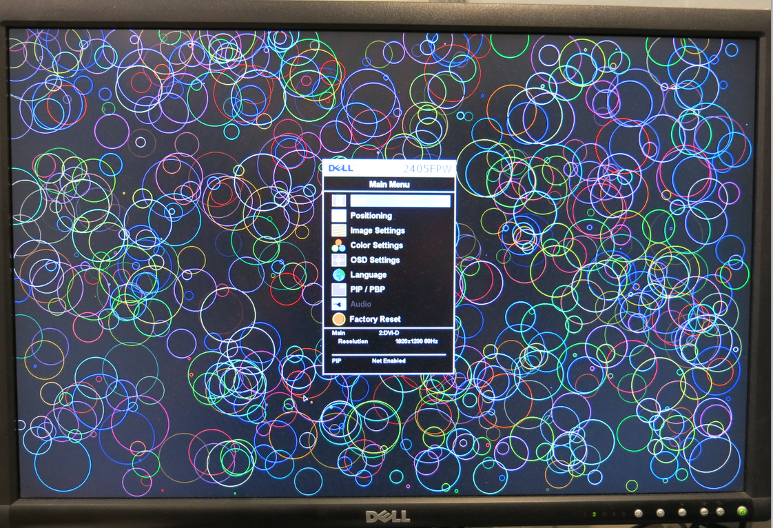
Good news @cgracey and @VonSzarvas ! All your hard work appears to have paid off, and my memory and video drivers started working first go on your next gen P2 Edge board that arrived here today for testing. Shown here is a PSRAM based framebuffer from this board delivering 1920x1200 video @ 8bpp over VGA which looks very crisp indeed. The P2 is running at 308MHz and the PSRAM is delivering 16 bits every 2 P2 cycles in each transfer (bursting up to 308MB/s). ![]()
Sneak peek:
Some delay test results have been obtained over a wide P2 operational range and there is good overlap at the frequency band transitions. The PSRAM is obviously being overclocked at the upper end but it still responded with good data well over 300MHz (at least at room temp ~25C). I'm not entirely sure what the rated speed of this particular PSRAM will be.
I'll probably have to tighten up the default delays for this board in my driver slightly. The Edge board is a little faster than the P2-EVAL test boards and so it doesn't need quite as much delay (as to be expected with its much shorter traces).
Right now I am currently putting together an update to my memory driver suite for release very shortly. It should now include both PSRAM and some async SRAM support as well as all the prior HyperRAM/HyperFlash stuff. Even though it is still effectively a beta release I do expect the PSRAM driver support to be fully complete and working in this first 16 bit only implementation as it was tested thoroughly some months back during development. The async SRAM driver however is much more recent and therefore less well tested and so that may not yet fully support every single API (TBD).
Comments
Wow, fast work!
Thats really exciting to have 1920x1200 available at 308 MHz...
Well much of this software work was done many months ago...so it was ready to try.
Yeah, it would be getting overclocked somewhat at that rate. By how much I'm not entirely sure. I think the previous tested parts were rated to 144MHz (i.e. P2 @288MHz) but they overclocked very well too. I'm not sure about these newer parts on the P2 Edge as they appear to be different devices.
Wow! That is fantastic, Roger.
This opens up huge possibilities.
Yeah it is a good result so far. I think it would open up the possibility for more video applications and to cache large amounts of data or for application development on board the P2 itself, using large working memory mapped files or data structures for temporary compiler output etc. 32MB is a decent amount of space to play with too. One of the keys there is having multiple COGs getting shared access to this memory, somewhat like a big HUB RAM (with less of the deterministic behavior, only strict priority + RR polling), and my driver was designed to support that.
It would also be neat if we could get Micropython to make use of this storage too, especially as its heap, though I'm not sure what the performance impact would be. The ESP32 platform uses this approach but it has HW support for reading the external PSRAM and I think it is already mapped into its address space.
One thing we need next is a Journaling file system for the 16MB flash chip.
Roger out of interest what clock rate is needed to get 1080 lines, rather than 1200?
I'm still hoping to one day be able to support that flash device as just another memory type which can be mapped into the global address space used by my driver. This would be very convenient for binary data reads and general data transfers from flash into RAM (transferring directly into PSRAM/HyperRAM etc via the existing memory copy APIs). Flash writes would need another filesystem layer sitting on top of it all. That's one missing piece.
I typically would use a P2 at 297MHz for that. But you could potentially halve it at lower colour depths or if you interlace etc.
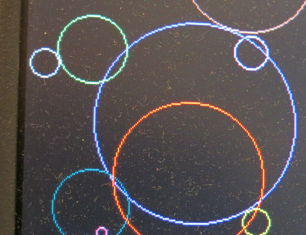
Roger, that screen shot is really great. Could you take another one, but up close on maybe just a portion of the screen?
My new monitors have only HDMI inputs, but I have a VGA-to-HDMI and a component-to-HDMI converter that I need to try. I'm partial to the latter because it only needs three pins.
Sure - wow my screen is dusty.
Yeah I am using a VGA to HDMI converter here too. Using it typically gives a very good result. Model CM201.
Thanks. Those pixels are perfect.
Yeah I think it's actually clearer in real life vs the photo above. Nothing is shimmering or double pixels etc.
Thank you @rogloh
Wonderful to see your results and all those coloured bubbles this morning.
That is great.
I remember maybe 30 years ago, someone used to advertise a GUI for PCs that could be configured to be as small as 4KB. It was written in assembly. There is some basic framework for realizing windows that can overlap. Probably can be reasoned out without too much effort. I kind of think it might be useful to have such a thing. 32MB can accommodate such stuff nicely.
The visual reward for your efforts. Well done to you, so far so good.
Yeah nothing stopping a nice hires GUI being developed for the P2 for those applications that can benefit from one.
One thing I'm still hoping for Chip, is for your SPIN 2 compiler to eliminate uncalled methods (dead code) from the binary image. That would allow larger "libraries" of graphics and GUI methods to be developed that won't have to bloat the client using them when the included routines are not called. FlexSpin can do this but official SPIN2 still can't AFAIK, unless you changed it recently.
Wow! 308 MHz...
XMM programming model has to be developed now for a P2
Now I have to wait until they appear in mouser.pl, as ordering from USA was not a good experience. The parcel traveled over a month through the USA, then a few weeks through the ocean, before it reached Europe, and then Poland, and finally problems with the customs office. Sent December 4th, received February 8th.
If they appear before our project ends, we will buy several of them for this project.
No, it doesn't remove dead code. Not sure when I'll get there. That almost needs another compiler approach.
It's a shame, I've found some bloat is likely inevitable if general purpose code is developed that needs to deal with multiple depths and graphics features which may or may not get used by the caller. We don't have conditional compilation (#ifdef) either which could also potentially help out there a bit too.
Are those SDR or DDR parts?
This PSRAM is SDR running at half the P2 clock speed (but 16 bit wide with 4x QSPI devices). This arrangement gets the same transfer rate as a single 8 bit HyperRAM running at sysclk/1 with DDR (whose clock frequency is the same as the PSRAM but clocks 8 bits on both edges).
Thanks for the answer. Yeah, I understand the performance ... Just that it could be double that again. I guess I'm a little disappointed because all the precision effort in board layout mostly only affects DDR writes. SDR doesn't need it because clock and data can be on alternate ticks (like how everyone bit-bashes SPI writes).
EDIT: I guess, to be fair, limiting to SDR data rate, particularly for reads, will always be more reliable. DDR writes had the possibility of going reliably faster than reads.
Hehe, Roger, you'll be loading up the DACs using the Jonny Mac board for fast video like that!
Time to put the whole kit in an oven and get a timing report when the RAMs are warmed up. That'll tell us if the memory driver may need a self-tuning function at higher frequencies.
Agree, that would be the best approach. I'm not setup for that unfortunately. Need a good thermal chamber to cycle the temperature and run automated testing, collecting results etc.
The self tuning thing is doable if we have a COG periodically make some transfers in dummy banks that overlap the real ones (so they can modify timing parameters without affecting existing settings) in order to home in on the best settings. Probably no temperature readings are required that way and it would be adaptive.
Yeah I was wondering about the trace lengths and path mismatch of that JonnyMac board with the pixels being clocked at 154MHz. I put the VGA board on P0-P7 which seems to have about the shortest traces. At one point I thought magenta coloured circles had separated into different red and blue pixels but it is probably just an artefact of the subpixel arrangement in the LCD monitor and all other colours look fine. I should try the VGA breakout board at the other positions. My VGA to HDMI converter would resync the pixel timing and it's just a short 30cm cable to that box from the VGA/AV breakout board.
Update: just tried it out and the pixels look just as clear in all port groups the breakout board was fitted in (0,8,16,24,32), so no issue there - at this frequency anyway. Actually the port group at pin 32 is good for the VGA breakout board as the LEDs can still be used with VGA (if you can share them with audio use or don't use audio).
FullHD @8bpp = 960x540@32bpp - a true color HDMI should be possible too
Yes of course, true colour is also possible at some lower resolutions or refresh rates where there is sufficient memory bandwidth for the data required.
I have an oven with 8 channel ADC and additionally 8 temperature probes setup for that sort of testing.
If there's some spin code that would run on the target device, either outputting serial data and/or relying on the external logging probes collecting data, then I could make time to run it.
I guess you'd want to see a table with: