

P2 Z80 Emulator
 pic18f2550
Posts: 400
pic18f2550
Posts: 400
in Propeller 2
Hello,
Is there an emulator for the P2 for the Z80?
And does it also support the unofficial commands?
The CP/M emulators I know only support the I8080.
Comments
Yes. While it’s not final yet, there is a link near the start of my RetroBlade2 you have it now thread.
I looked at the OS228c-2020-12-15A and the zicog_v0_10.
In the OS I could not find a z80 emulator (obj/pasm).
In the zicog_v0_10 is only the P1 variant with 11 open sites.
These links may be of interest. Obviously the CPM uses my Z80 emulator
https://forums.parallax.com/discussion/173395/clusos-propeller-os-v2-38-includes-sd-driver-and-fat32-object-plus-serial-driver
[https://forums.parallax.com/discussion/comment/1499300](https://forums.parallax.com/discussion/comment/1499300)
https://forums.parallax.com/discussion/172556/clusos-retroblade2-your-board-s-have-arrived-so-what-to-do-next/p1
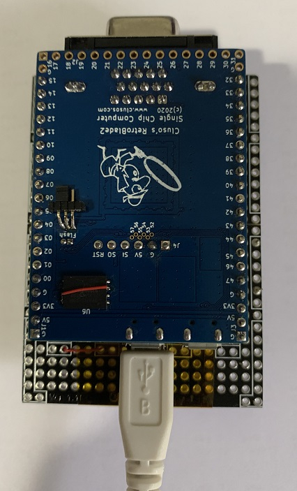
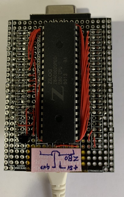
FYI I am driving a Z80 (Z84C0020) mounted on a protoboard mounted on top of my P2 RetroBlade2 board. The P2 drives the Z80
The P2 provides the CLK to the Z80, RESET via a transistor, connects A0-15 & D0-7, and the M1 MREQ RD & WR pins.")
I can see the addresses cycling after reset, with M1 MREQ and RD pins changing.
Now to inject the opcodes
Oh, now I understand, it is not an emulation but an adaptation of a Z80 CPU on the P2.
I can search a long time for the Z80 ALU.
So there is only for the i8080 a complete emulation on P1.
This also explains why so many emulations are doomed to fail.
No!
On the P1, heater wrote the Z80 emulation called ZiCog. I added the OS and some of the CPM stuff plus the drivers to the SRAM etc. It runs on my RamBlade P1 board using the SD as 8 x 8MB HDDs. There must be a few instructions not correctly emulated as cobol under CPM does not run, but most of the CPM programs run properly including wordstar and msbasic etc. Pullmoll later wrote a Z80 emulator too. The P1 emulation does not use precise clocking but runs about the speed of a 4MHz Z80.
On P2, I have written a Z80 emulator based on pullmolls P1 Z80 emulation. This is what I use in the P2 CPM. It runs msbasic but I've not tried other programs. Chip, baggers and coley have an 8080 emulation working for the games controller they are using for the space invaders etc.
Recently I bought a Z84C0020 (20MHz CMOS Z80) and last week I hooked it up to my P2. I want to drive the Z80 to validate the instructions in my Z80 emulator.
I like this")
A Silicon Data Sheet !
It's running instructions
I am plugging instructions in but I am not actually using the addresses generated by the Z80 to read a datablock.
Pics of my setup
Most software for CP/M is written for the 8080 and some has been adapted somewhat to the Z80.
I myself would like to use CP/A again. That was written completely on Z80.
The heavy use of IX & IY commands hinders the use of ZICOG because the index commands are incomplete.
Doesn't the Z80 run at 5V and the P2 at 3.3V?
Do you have a level conversion inside or do you connect the pins directly together?
Baggers also has a functional Z80 emulator running, currently it is woven into his not yet released ZX Spectrum emulator.
I need to catch up with him and see where it's up to.
Yes, it’s 5V to 3V3. The Z84C00 works fine with TTL voltage inputs which the P2 satisfies. For Z80 outputs I use a resistive divider 1:2 in to P2. It was easier to solder on a breadboard than buffer chips")
The clock direct from P2 works just fine")
BTW I thought heater had implemented most of the special Z80 instructions. I know they are implemented in my P2 version although I am aware there is a bug or two, probably to do with flags.
If I get time over the next day or so, I will be checking the write from the Z80.
Cluso, are the BUSREQ and BUSACK pins connected to the P2?
If so, you could examine the Z80 at the machine cycle level, not instruction level, as follows: assert /BUSREQ, wait for /BUSACK, then assert /RESET. This mechanism permits the Z80 to be "frozen" then immediately reset at the end of any M cycle in any instruction. The reset zeroes PC and I & R, disables interrupts and selects IM 0 but all other registers are preserved including the internal WZ. This has been tested and works.
More info at
https://stardot.org.uk/forums/viewtopic.php?f=3&t=15464
and more specifically here
https://stardot.org.uk/forums/viewtopic.php?p=211197#p211197
The Z80 designers added a way of reading the WZ register (actually WZ[13:0]). How this is done is interesting and is mentioned in detail in the links above.
A CMOS Z80 has at least one "undocumented" instruction that is different from the NMOS version. Flag bits 3 and 5 might also differ very occasionally, I need to check. Testing with a CMOS CPU allows you to stop the clock for an unlimited period of time.
EDIT:
Extra info added.
Thanks for the links Tony.
I don’t have the BUSREQ & BUSACK pins connected to my P2, nor NMI, INT, IOREQ, REFSH, WAIT & HALT currently.
My proto board only has 2 sets of 16 pins to the P2, plus 5V, 3V3 and GND. Currently 2 are unused intended possibly for IOREQ and INT.
I am just driving CLK as required, very slowly at present using spin")
Not sure if I will convert to pasm later or not.
From the trace I showed above, you can see the Refresh address coming out on the address pins.
BUSACK could be avoided if CLK toggled enough times after /BUSREQ and before /RESET.
CLK cannot be slow for NMOS Z80 CPU because three transistors are used instead of flip-flops to select DE/HL, AF/AF' and BC-DE-HL/BC'-DE'-HL'.
As I said above, I am using a Z84C0020 CMOS 20MHz cpu so I can stop the clocks or use any variation below 20MHz")
The P2 works nicely as a peripheral substitute.")
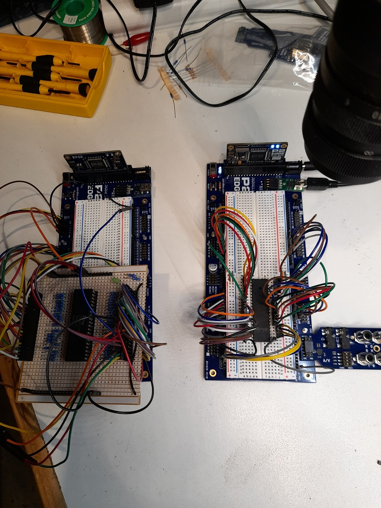
I currently have two P2 setups, one running a Z80B and the other a W65C02.
The Z80 has run a Processor Technology SOL-20,Radio Shack TRS80 and a Exidy Sorcerer configurations with matching video emulation on HDMI.
Other retro machines are in the works (Maybe Osborne,Microbee,Apple,OSI) when time permits.
Nostalgic fun!
You can see the limiting resistors on thZ80 setup on the left for 5V interfacing.
This hacked Z80 setup runs Ok up to 3MHz. The 6502 is still being tested.
Next job is to design a PCB with both CPU's together and use BUSRQ and BE to select the desired flavor.
Did you mean CLK via a transistor? Other inputs could be 3.3V CMOS or 5V TTL but CLK high should be nearer 5V.
Re the 32 pins you have available, apart from A0-A15 & D0-D7 I suggest
CLK, M1, MREQ, IORQ, RD, WR, RESET and one of BUSREQ / INT / NMI.
Perhaps you could use jumpers for the latter three? BUSREQ would be best for examining the inner workings of Z80 instructions as already mentioned.
P.S. I've also studied the Z80 Special Reset
http://www.primrosebank.net/computers/z80/z80_special_reset.htm
I am driving CLK directly, no resistors or transistor or gate.
Works fine for me, but I have not been going fast and it's not a commercial offering, so meeting specs is not a requirement.
@ozpropdev Nice work")
Seems we're in SYNC with our experiments!
My Z80 clock source is simply driven direct from a P2 smartpin @ 2MHz, 3v3. Works fine here too.
Now i have decoded writes and using the
ld (**),a
To write out the a register.
Now to implement 64KB of RAM/ROM and load it up. I can use my cpm code for this")
Cluso99 your variant to assimilate a real Z80 would be a possibility to verify the ZICOG.
Opcode with which the Z80 is fed.
POP AF
POP BC
...
EXX AF, AF'
EXX
POP AF
POP BC
....
RET 'load PC
'ALWAYS 4 TEST BYTE OR FILL WITH NOP
CALL $0000 'save PC
...
PUSH BC
PUSH AF
EXX
EXX AF, AF'
...
PUSH BC
PUSH AF
I've been working on a flag-perfect, M-cycle-accurate Z80 emulator for the P2. Some more info on exactly when destination registers are written is required.
It seems that if an instruction modifies the flags, the F register is written during T1 of the next instruction, due to fetch-execute overlap. Bus request & reset could/should stop F from being changed.
I suspect ALU results are written to A during the next T1, but do register-to-register or immediate-register loads happen then or during the last T-cycle of the actual instruction?
The following would be good tests for bus request & reset during the last M cycle of the last instruction (as shown by asterisk):
EDIT:
Above assumes a reset stops any register writes during the next T1 from happening. If not, it would impossible to distinguish last T and next T1 writes using bus request & reset.
The reset state of the registers and flags is defined in Zilog's Z80 specifications.
But they represent the common minimum.
Zilog has given permission to many companies worldwide to use their patent.
The basis was always the specifications and not a finished chip, so there were different implementations and technologies worldwide. From NMOS to GaAs variants.
https://www.zilog.com/index.php?option=com_doc&Itemid=99 --> Classic Products --> Z80
Easy to see what the register values are...")
Just push them all
It's working
I have chosen this emulator because it seems to be the best for my project.
'' +--------------------------------------------------------------------------+
'' | Cluso's Z80 emulation for P2 v0.xx |
'' | Based largely on Z80 emulation code for P1 by pullmoll (Juergen) |
'' | qz80-0.9.32\qz80.spin |
'' +--------------------------------------------------------------------------+
'' | Author(s): (c)2010 "pullmoll" (Juergen) (original code) |
'' | (c)2019 "Cluso99" (Ray Rodrick) (rewrite for P2) |
'' | License: Juergen gratiously gave me permission to modify his code |
'' +--------------------------------------------------------------------------+
I was able to fix some small things:
The R register is incremented by 1 to 127 on each pass.
I removed the break after 60 steps.
I added a pause at the program start and in the line output to see the result in the console better.
The CB part worries me the most because I don't understand it. (LMM)
http://z80.info/decoding.htm
cb_xx {cb} call #rd_opcode mov opcode, alu '' preserve opcode shl alu, #1 add alu, table_cb test opcode, #%11000000 WZ '' first quarter? $00-3F if_z rdword lmm_pc, alu ''\ yes, dispatch now if_z jmp #lmm_pc ''/ mov alu, opcode and alu, #7 test opcode, #%01000000 WZ test opcode, #%10000000 WC add alu, #$40 if_c add alu, #$08 '' if $8x if_c_and_nz add alu, #$08 '' if $Cx shl alu, #1 add alu, table_cb shr opcode, #3 '' bit number to 2..0 '?????????? and opcode, #7 '' mask bit number mov tmp, #1 shl tmp, opcode '' make bit mask for BIT/RES/SET rdword lmm_pc, alu ''\ dispatch now jmp #lmm_pc ''/LMM is/was a mode used in P1 where hub code was copied, instruction by instruction, into cog for execution in a 4 instruction loop. It allowed assembler code to reside in hub thereby extending the size of code considerably. But of course it was much slower.
Any references to LMM in the code is just a name carry over. When I started the P2 code, hubexec was not on the drawing board, so I was prepared for the code to be lmm (large memory model originally developed by Bill Henning). Some of the P1 ZiCog code uses my overlay technique to quickly load a routine from hub to cog to then be executed in cog.
IIRC any label beginning with lmm_ resides in hub and runs as hubexec code. It’s the less used Z80 instructions because hubexec is slower.
I presume you know about the 3 prefix instructions for the Z80?
I have my P2 now serving up the 64KB from hub to the Z80.")
I’m booting the first part of the CPM boot code but I have the SD CPM code patched out.
Currently I am trying to get a version of zexall or zexdoc assembling on my pc under windows so I can include it in my P2 code to test out the real Z80. Zexdoc and zexall are z80 programs that are used to verify z80 emulations. It’s a nightmare to get a windows cross-assembler that will do the macro expansions used in the zexdoc/zexall code. They all have incompatibilities with each other.
I’ve been asking over on the retrobrew forum.
In the 80' years I programmed the Z80 (U880) in assembler. (is long ago heer)
I guess there is something wrong with the pointers written in lmm_pc.
Have you tried the Arnold assembler yet?
john.ccac.rwth-aachen.de