

Quad Rover/ Propeller help requested
 Mark Kibler
Posts: 546
Mark Kibler
Posts: 546
Dear Friends,
We're trying to get a Parallax Quad Rover up and running but we're not having much luck getting the RC receiver to connect with the Propeller board. Here's the email I sent to Andy Lindsay at Parallax today. We're using the 5 programs (in the attached photo) in an attempt to connect the receiver with the Propeller1 board. Your help, suggestions and dialogue are very much appreciated. ~ Mark in Cincinnati
" I'm puzzled about how to get the remote control receiver to connect to the Propeller board on the Quad Rover. We followed the instructions on 'SetTrim_v1.0' to test the connection between the receiver and the servos and all we get on the serial terminal screen is "No signal."****
Setup:
• Using 10KΩ series protection resistors, connect channels one through four,
from an RC receiver, to four consecutive Propeller I/O pins. Channel one
should be connected to the lowest numbered I/O pin in the series and the
constant 'FIRST_CHANNEL' should be set to that I/O pin. Channels two through
four should be connected incrementally to the next tree I/O pins.
• To use this program, press F11 to load it to EEPROM, then, with a serial
terminal, open the com port that is connected to the Propeller Control Board
at 9,600 baud with 8 data bits, 1 stop bit, and no parity.
Usage:
With the radio transmitter turned off and a terminal program connected to the
Propeller, the following text will be displayed:
No Signal
Right X: Not set
Right Y: Not set
Left Y: Not set
Left X: Not set
We have done steps 1-3 below DONE. All wires are connected correctly to the RC receiver and to the Propeller board
1) "Using 10KΩ series protection resistors, connect channels one through four, from an RC receiver, to four consecutive Propeller I/O pins.
2) Channel one should be connected to the lowest numbered I/O pin in the series and the constant 'FIRST_CHANNEL' should be set to that I/O pin. 3) Channels two through
four should be connected incrementally to the next tree I/O pins.
3) To use this program, press F11 to load it to EEPROM, then, with a serial
terminal, open the com port that is connected to the Propeller Control Board
at 9,600 baud with 8 data bits, 1 stop bit, and no parity."
ALSO DONE:
1) "With the radio transmitter turned off and a terminal program connected to the Propeller, the following text will be displayed:
No Signal
Right X: Not set
Right Y: Not set
Left Y: Not set
Left X: Not set"
The words "No signal" appear horizontally and vertically on the text screen (see attached screen shot) but the words 'Right X: Not set", etc. do NOT appear below "No signal"
Sometimes the words "No signal" appear just horizontally. Other times there are a few letters of random punctuation beneath it.
When we connect the receiver wires directly to one of the servos on the Quad Rover, the RC controller runs the servo(s) just fine.
What are your insights and suggestions on how we can get the RC receiver to connect with the Propeller board? Thanks for your reply.
Kind Regards,
Mark Kibler
Comments
Mark,
I never had to use the 10K resistors on the inputs. You should be safe to connect the 4 receiver channels directly to the control board. Give that a shot.
@Publison
Are those RC receiver to Propeller connections inputs or outputs? (From propeller perspective)
I thought those receivers ran at 5V logic levels. If that is true, and they output to the Propeller, I'd suggest fit 3.3k series resistors or higher. 10k likely still ok if the userguide states that.
If however they are only inputs from the Propeller to the receiver, then can be OK to leave the resistors out provided there's no high pulse during power-up/etc... In case of uncertainty just include the resistors.
If the resistors are the cause of failure in comms, then might be better to add 10nF ceramic caps in parallel with each resistor, instead of removing them entirely.
You'd know for sure from experience of course!!
Inputs. There are 10K series resistor already onboard the control board AUX8...19.
I have used Spektrum receivers on my Quadrover with no resistors on inputs.
Control board schematic.
Thanks for the Propeller board documentation. With the resistors removed we're having the same problem… no input signal from the RC receiver. The wires are inputting from the RC receiver at I/O pins 8, 9, 10, and 11 per: instructions in the operating manual.
Any suggestions?
How is the receiver being powered, (pins above channel 1 on the receiver)? 5-9 volts would be good.
The receiver gets power through the Propeller board 3-pin wires. We also tried it by powering the receiver with a stand-alone battery and we got the same results-- the receiver wouldn't connect to the Propeller board.
So I can understand you’re logic and problem-solving/ thinking, why do you ask? Why would that matter?
To get power to the receiver the power switch has to be in the upmost position (Prop ON, Servo ON), but you probably already know that.
.
We're using an analog RC transmitter/ receiver (no digital display screen), the AR410 receiver and the Spektrum DXs. The output signal must be a pulse just like with a digital RC transmitter/ receiver. Does this matter? Still no signal to the Propeller board from the receiver.
Put all these file in one folder. I have used a couple of Spektrum combos on the Quad rover.
What happens when you run QuadroverRadioNavigation_v1.1 without running SetTrim.spin
The same thing, as I recall. But I’ll try that again and report back. Thanks for the suggestion. And THANKS for the files too. These are the ones I’m using. I’ll check to be sure the code matches.
Nothing new happened when we ran QuadroverRadioNavigation_ 1.1. The Serial Terminal window showed that the computer was not receiving a signal (no RX green light.) The TX light was also SOLID blue. Also, no ‘No signal’ message in the text window.
When when we run SetTrim_v10 we get a pulsing RX green light (receiving a signal?), a solid TX (transmitting) blue light, and a “No signal” message in the text window. Beneath it three or random characters/ punctuation marks appear. These are not always the same random characters/ punctuation marks leads me to believe that some sort of a scrambled input signal is coming through.
Does the solid blue TX light mean that mean it is, or isn’t transmitting. It has to be (at some level) because we can load code to the Propeller board.
We just re-ran SetTrim and compiled it. The message “No signal” appeared horizontally and three random punctuation characters appeared vertically beneath it where the words “No signal” often appear vertically, but not always.
When we disabled and then enabled the Serial Terminal screen the random vertical characters disappeared but the horizontal message “No signal” remained.
Serial terminal should not work with the Navigation program. I just wanted to see if the servos responded just using the Navigation program. Don't use the set trim just now.
Simple question:
When the computer sends a signal (TX) to the Propeller board; and when the remote control receiver connected to the Propeller board sends a signal from the radio control transmitter to the Propeller board (RX); what color should the TX and RX lights on the Serial Terminal screen be?
When we run SetTrim_v1.0, the TX light is solid blue and the RX light quickly pulses green.
I believe the blue TX light should also be pulsing green. Which is correct when the receiver and the Propeller board are “hand-shaking” TX <———-> RX
Running QuadRoverControl_v1.0 by itself **causes the throttle servo to pulse ** until the Propeller board is shut off. The servo does not respond to a signal from the remote control transmitter/ receiver.
Hi
I have been following this with an amount of confusion- the sentence
...doesn't make any sense to me. It sounds like you are connecting the radio control receiver to the prop rx pin somehow. Perhaps I mis-understood. But if you are then that can't be right? (can it)
Sorry to butt in but without a picture of you connections its hard to follow.
Dave
You're not butting in at all Dave. I appreciate all the input we can get.
Yes, there are four wires that come from the radio control receiver-- channels 1, 2, 3 and 4 wires. They are currently plugged input pins 8, 9, 10, and 11 based on (my understanding of) the document 'Propeller QuadRover (28195) Example Program Instructions' (attached).
We ----->
"1. Connect the R/C receiver to the Propeller Control Board.
2. Following the diagram below, use four female to female servo extension cables to connect
channels one through four of the R/C receiver to auxiliary connections 8 through 12 on the
Propeller Control Board. It is important that channels one through eight are connected in order to
connections 8 through 12 on the Propeller Control Board, otherwise the QuadRover will consider
the R/C receiver's output to be invalid."
The last one seems like a significant sentence -------> "...otherwise the QuadRover will consider the R/C receiver's output to be invalid."
**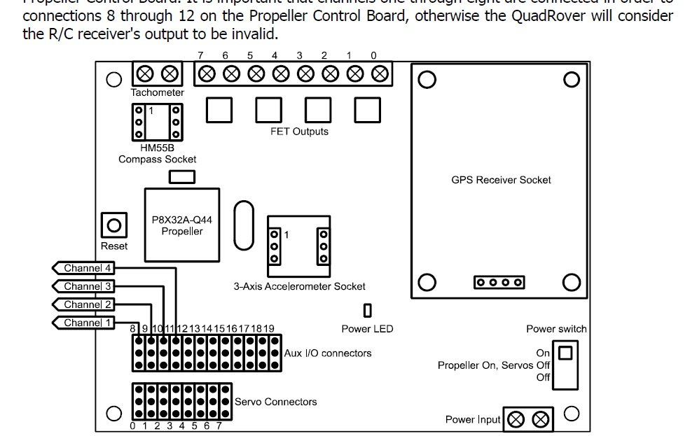
See the attached photo which shows where to attach the 4 wires coming from the RC receiver to the Propeller board
How do you read this? Does that seem right to you?
Thanks,
Mark
The documentation in "QuadRoverRadioNavigation_v1.0.spin" (quotes below) says that we SHOULD run SetTrim before we run the other programs.
"Before using this object (QuadRoverRadioNavigation_v1.0.spin), follow the directions in 'SetTrim_v1.0.spin' to ensure that the R/C transmitter is functional and properly trimmed,
**** This is where we are right now; this is where we are stuck. ****
Then follow the directions in 'QuadRoverControl_v1.0.spin' to calibrate the throttle and brake servos.
Do you think we should we be loading and running a different program first, before 'SetTrim_v1.0.spin' ?
Hi
Having sparked my interest I looked at the spin files from above but could not see SetTrim_v1.0.spin.
Can you attach a copy on your next post please. The way you have connected would seem correct despite the somewhat cryptic instruction-
I don't think you will do any damage just going straight ahead and skipping the 'SetTrim_v1.0.spin' as it seems to be just checking transmitter settings, if that works then don't worry if not then back to the drawing board.
The strangely named power switch just seems to enable the servo and aux socket power not as you might think the board power- if the circuit diagram is right, but this must be set to 'on'.
Its also important to get the servo plug orientation right- there are barely visible color names 'w r b' referring to w=signal, r=+5v, b=gnd or 0v.
Nowhere on parallaxes web site using search could I find any reference to the Quad Rover!
Dave
Dave,
The R-G-W wires are properly connected on both the Propeller board and the RC receiver. Red-to-red, etc. Attached is the "SetTrim" file you asked for. This is the one we're starting with and trying to run. Let me know what you think.
Thanks,
Mark
Mark, can you post photos of your setup?
Here you go. Let me know if you need other photos.
Connections look fine.
Where would you go from here to troubleshoot the “no signal from transmitter/ receiver” problem?
I would write a small bit of test code that looks at and displays the inputs from the RC receiver. I find it easier to test things in isolation before integrating the parts.
I don’t code so well. Plus, we connected stand-alone servos to the RC receiver and all four channels worked fine. Then we wired the RC receiver straight to the throttle servo wire on the Quad River and drove it in a straight line across the parking lot. We bypassed the Propeller board completely. So the problem is between the RC receiver and the Propeller board “somewhere” in the programming…?
Today's thoughts...You said you connected the receiver to stand-alone servos, where they the servos on the QR? What happens when you connect the servos on the QR directly to the receiver with power and the power switch in the SERVO and POWER position .
Sounds like the transmitter and receiver are working correctly as you found out at the hobby shop.
Software has been stable for >10 years so I really don't think that's the problem, but I could be wrong. I'm thinking it MIGHT be a hardware problem. I hope not. The prototype QR was built on a Project Board and can be duplicated if I can get the original parts list from David Carrier at Parallax. The QR Control Board is no longer available.
Has your QuadRover ever run before when you first got it?
I'm wondering if the 10k series resistors on the AUX I/O input are a little high for your receiver.
You posted this in the Activity page:
"Finally, when we start the gas powered motor and it's running, two of the wheels on one side of the rover rotate but the wheels on the other side don't rotate. Any idea why this is?"
Does this still happen?