

dual stepper motors
 bbrien
Posts: 603
bbrien
Posts: 603
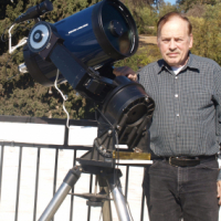
I have a small Mac-Cass telescope which I damaged by plugging into a power source which was twice the rated voltage and it ate the processor. It uses two stepper motors in the drive system. The original system consisted of four pushbutton switches arranged as a compass , plus a switch controlling one of three speeds. I have a spare board with a Propeller Mini which will be using to run system. There are two groups of inputs with a total of nine inputs and eight output pins. Six of the outputs will deliver high or low and two will output a frequency pulse. Four inputs will connect to a hand box, and another will connect to a guide camera and the last will generate four different frequency pulses. I have two different programs which I would like to combine into one program .
Comments
This is as far as I have gotten on my new program.
`CON
xin_freq = 5_000_000
clk_mode = xtal1 + pll16x
          RA                 = 0
          DEC              = 0
          NORTH        = %0001
          SOUTH        = %0010
          WEST           = %0100
          EAST            = %1000
          NORTH_B   = %0001
          SOUTH_B   = %0010
          WEST_B      = %0100
          EAST_B       = %1000

 CON   'Pin Assignments
          NORTH          = 0
          SOUTH          = 1
          WEST             = 2
          EAST              = 3
          RATE              = 4
          AUTO_N        =15
          AUTO_S         = 16
          AUTO_W        = 17
          AUTO_E          =18

          RA_SPEED       = 10
          RA_DIR            = 11
          DEC_SPEED    = 12
          DEC_DIR         = 13

           LED_1             = 6
           LED_2             = 7
           LED_3             = 14
           LED_4             = 15
           RA_RATE         = 8,_0
           RA_AUTO     = RA_RATE
           DEC_RATE       = 8,_0
           DEC_AUTO   = DEC_RATE
           SLEW_1         =  2
           SLEW_2         = 4
           SLEW_3         = 8
           SLEW_4         = 16
OBJ
step1 : "stepper"
step2 : "stepper"
PUB Main | update, slew_rate, auto_old, auto_new
`
in pub main I have dumped most of the variables since there is no serial used in the new system. What should I use for the hand box constants.
bbrien,
Forgive my Quality background showing, but I think the first thing that you should do is prevent the wrong voltage from frying all your electronics.
You don't want to make the same mistake again in the future.
Astroview did not bother to use voltage regulators in their circuit or any other protection from overvoltage.
Checking the program for errors and an error pops up at CON "DEC_RATE = 8,_0" "expected a unique constant name or"#" ". It didn't tag the line "RA_RATE = 8,_0".
How can I save my project to a file outside of the propeller library so I can ppost to the forum to have someone help correct the errors. The IDE will not let me do it with all the mistakes in it .
I printed the program and scanned to a folder and now I send the copies to the forum . This is my hopefully completed program.
bbrien,
Where did you get those 2 Spin programs and where are the Stepper and dual_motor_ez_MOD Objects from?
Also what model Telescope and Controller is this for?
It's hard to see what these programs do because there are few if any comments.
Here is how you attach code:

The two programs were originally written by Chris Gadd or at least given to me by Chris. (SPI pg 6, 2020-08-14) and then modified by Dave Hein(using multiple frequencies to control a stepper motor, '2020-12-07,) He also generated the obj. stepper.spin. "Dual motor ez mMod is by Jon McPhalen.
My original code is attached -- I have no idea what's going on in the "_MOD" version, but I suspect it's probably not good. FWIW, I use this object in camera control platforms for JonyJib.com; that is to say that it has been proven in commercial applications.
bbrien,
I see that both files were from Dave Hein as well as Stepper.spin, though one of the last comments he makes is to change the SCALE value to 4.
The last version of Stepper.spin that he posted on 2020-12-07 has SCALE=40.
https://forums.parallax.com/discussion/172479/using-multiple-frequencies-to-control-a-stepper-motor/p2
Also you say that you were using 8 Hz on the Orion and that the tracking about a minute slow in minutes.
The Telescope Mount DH15 that you attached has RA_RATE=9_5, which is 9.5 Hz.
https://forums.parallax.com/discussion/172479/using-multiple-frequencies-to-control-a-stepper-motor/p3
Telescope Handbox DH9.spin is here posted by Dave Hein on 2020-08-29.
Meade LX50.
https://forums.parallax.com/discussion/comment/1505434#Comment_1505434
The newest jm_dual_motor_ez.spin that I know of is from 06-20-2020.
dual_motor_ez_MOD.spin is part of Telescope Mount.zip that Chris Gadd posted on 2020-08-14, which he says has "one small edit".
https://forums.parallax.com/discussion/171864/spi-solved/p6
What setup are you using because in SPI you were using 2 Propeller Flips, and an MC3479 and a UDN2993 in Control a Stepper Motor?
In the future if you are going to cut and paste from one program to another then include the comments.
Also if you change something PLEASE PLEASE PLEASE add a comment on what you changed.
Jon,
The only change that I notice is in Set_Speed.
The line that controls the Reverse speed has been altered.
pub set_speed(motor, speed)

'' Set motor speed in 0.1% increments (-100_0 to 100_0)

  speed := -100_0 #> speed <# 100_0                             ' limit range -100.0% to +100.0%

  if (speed == 0)                                               ' stop
    if (motor == 0)
      m0ticks := 0                                              ' set pwm cycle to 0 (always low)
      low(m0dir)
    elseif (motor == 1)
      m1ticks := 0
      low(m1dir)

  elseif (speed > 0)                                            ' forward
    speed := speed * pwmticks / 100_0                           ' convert speed to pwm ticks
    if (motor == 0)
      m0ticks := -speed                                         ' set speed for pwm cog
      low(m0dir)                                                ' set direction to forward
    elseif (motor == 1)
      m1ticks := -speed
      low(m1dir)

  else                                                          ' reverse
'   speed := (100_0 + speed) * pwmticks / 100_0                                ***** Original *****
    speed := ||speed * pwmticks / 100_0                         ' convert speed to pwm ticks   *** Added ***
    if (motor == 0)
      m0ticks := -speed                                         ' set speed for pwm cog
      high(m0dir)                                               ' set direction to reverse
    elseif (motor == 1)
      m1ticks := -speed
      high(m1dir)
In post #178, Chris states:
https://forums.parallax.com/discussion/171864/spi-solved/p6
"That is JonnyMac's dual-motor driver with one small edit, just use all the files in the zip, you don't need to write anything, it's all in the zip file.
With the driver as originally written, setting the motor speed to 10_0 created a pulse that was high for 10% of the period with the direction output low, which is fine, while setting it to -10_0 created a pulse high for 90% of the period and high direction output. I've never used a h-bridge before, but from looking at the UDN2993 datasheet it seems that would run the motor at high speed in reverse. "
bbrien,
Let's start from the beginning.
So your system is a Control handbox, a Guide Camera, and the Telescope, correct?
Now for each component of the system.
There is a handbox with Compass-Direction buttons and a speed control switch.
The buttons are pushbuttons, correct?
Is the switch Rotary (rotates) or is it a Slide switch or something else?
Are the speed settings slow, medium, and fast?
How is the control box powered?
What is connected to the handbox?
The Guide Camera obviously needs power, so what is it connected to?
What other connections are there to the camera and what do they do?
I assume the Telescope Drive system uses Geared Stepper motors.
Do you have any specifications for them?
Are the Stepper drivers on the Telescope or in the handbox?
What connections go to each motor?
The First step is that you need to Define the Problem that you want to solve, IN DETAIL!
NEW SYSTEM (1) Hand Box ; Four push buttons(North, South, West and East) connected to Prop chip by plug. (2) guide camera: Two connections one going to the prop chip and one going to a laptop computer, which powers the guide camera. (3) chip box with two recepticals (hand box and camera). There is also a lone push button switch in the enclosure holding the prop chip, I want read all inputs in order and test the state and if high , take the appropriate response(turning on a motor. I do not have geared steppers on this mount. The motors are attached to the mount and there four wires on each motor, Two for each coil. There are four speed setting plus the tracking speed.I think the easiest way to run the handbox and mount programs on the same Prop is to create a virtual serial link between the two objects. So instead of using FullDuplexSerial you could create an object that contains the same methods that are used by the two program. There are only three methods used, which are start, tx and rxcheck. I don't think start is needed, so you would just need to implement tx and rxcheck. The mount program should probably be the top object, and it would reference the handbox object, and start it by calling cognew(handbox.Main, @handboxstack).
Do you need to change the stepper motor code? It seems like you can use the same code with only minor changes for the frequencies as long as you use the same driver chip.
EDIT: I've attached the virtual serial object. Use this instead of FullDuplexSerial to communicate between the handbox and the mount objects.
EDIT2: You should also comment out the debug code in the handbox object. Otherwise, both the handbox and mount objects will be using the console serial link.
I am in a state of confusion, there is no processors in the hand box, only 5 wires connecting the four switches to the propeller mini. Only one prop in use in the whole shebang.
So you would run the handbox object and the mount object on one prop.
Yes , The hand box only has four switches and the camera only has four switches( opto-isolators). I'll check back later, going to bed now.
I have attached new versions of the handbox and mount objects. Mount is the top object, and it references the handbox object. They communicate through the virtualserial object instead of using FullDuplexSerial. You just need to change the pin assignments, and the values that control the frequencies.
By using the virtualserial object I minimized the amount of changes done to the original code. The code could be simplified by having the mount object call the main method in the handbox object, but this would require substantial changes. This would eliminate using another cog, and eliminate the need to use virtualserial. I think it's best to get it working first with virtualserial, and then simplify it later if desired.
I downloaded the two programs but I don't know how to install two programs into one chip. There are also two stepper motors in this EQ-2 mount . Disregard the Hand box and pretend there are eight pushbutton switches controlling the two motors. Check post #7 of this thread.
It's only one program, but with multiple object files. "Telescope mount dh16.spin" is the top object. Just compile that file, and it will pull in all the other objects.
But will it handle two stepper motors.
I updated the mount object to handle two stepper motors. I also changed the pin numbers to match those in your PDF files in post #7. The new objects are attached below. "Telescope mount dh17.spin" is the top object. Compile this one, and all the other objects will be automatically linked in.
I understand that the handbox and mount hardware are not the same as your previous project. The software doesn't know about the hardware implementation. It only understands pin numbers. If the pin numbers are correct in the code that you posted, then the attached code should work.
bbrien,
Based on your description above, your system looks this:
 ___________        __________        ______________
|           |      |          |      |              |
|  Handbox  | ---> | Chip box | <--- | Guide Camera |
|___________|      |__________|      |______________|

 _______                   __________        ______________                   ________
|       | ---> North ---> |          |      |              |                 |        |
|   N   | ---> South ---> |          | <--- | Guide Camera | <--- Power <--- | Laptop |
| W   E | ---> East ----> | Chip Box |      |______________|                 |________|
|   S   | ---> West ----> |          |
|_______|                 |       PB |
                          |__________|

 _____________
|             | ---> Coil 1
|   RA Motor  | ---> Coil 2
|             |
| -Telescope- |
|             |
|  Dec Motor  | ---> Coil 1
|_____________| ---> Coil 2
What does the pushbutton on your "Processor Box" do?
Your Handbox only has Compass pushbuttons now, so where will the Speed control be?
Does the laptop only power the Guide Camera (I am not familiar with how these work)?
What input does the Guide Camera sent to the Propeller (digital, serial, other)?
Your stepper motors are Bipolar.
Are there labels on each stepper motor and what do they say?
Is each stepper motor the same?
What are the colors of wires that go to each stepper motor?
Do you know which 2 colors connect to each coil?
Do you know the step sequence for each stepper?
You didn't mention what the Stepper motors connect to or where the Motor Driver is located.
Ideally the motor drivers should be close to the motors and have a power source nearby also.
Push button on processor box sets the speed( push 1 = Low, push 2 = medium, push 3 = high, push 4 = crazy fast). The laptop computer contains the software to operate the camera and communicate with the mount( second cable from camera to mount has four opto-isolators which act like switches) . No labels on steppers. The same. Colors are red, green, yellow, brown. Red-Brown, yellow-green. no. Shafts connecting to slow-motion controls. ( picture in post 22). About four feet away.
Dave, IDE looking for virtualserial.spin
virtualserial.spin is attached to post #15.
Is this the optional Orion EQ-2M electronic drive that you have, because the Orion EQ-2 is only a mount?
https://www.highpointscientific.com/orion-eq-2m-electronic-motor-drive-for-eq-2-equatorial-mounts
https://www.telescope.com/assets/product_files/instructions/29168_02-09.pdf
That they are. and thanks Dave.
program made it through the tool but displayed a " unable to locate a serial port so I am searching for a prop plug and my cable. Let you know how it works as soon as I find it, otherwise I'll have to purchase a new one.
bbrien,
Do you know what the gear ratios are for your Orion EQ-2?
All I could find online was someone was that the RA gear is 100 teeth.
130:1 and 144:1 seem to be the most common RA gear ratios for Equatorial mounts.
There is about a 10% difference between the 2 ratios.
The RA axis should rotate one revolution in a little less than 24 hours, so the mechanics of the gearing and motors need to be known to calculate the correct pulse rate.
Also, is your Guide Camera auto-guiding, and if so what's the make and model?