

Benewake TF02-Pro Lidar
 HughN
Posts: 4
HughN
Posts: 4
I need a nudge in the right direction, please. It's been a while since I've worked with the Prop.
I have a Benewake TF02-Pro Lidar (manual here) and have written some code (attached) to receive data from the Lidar one byte at a time via Full Duplex Serial and send it to to the Parallax Serial Terminal as a decimal via Full Duplex Serial.
The format of the message as described in the manual is:
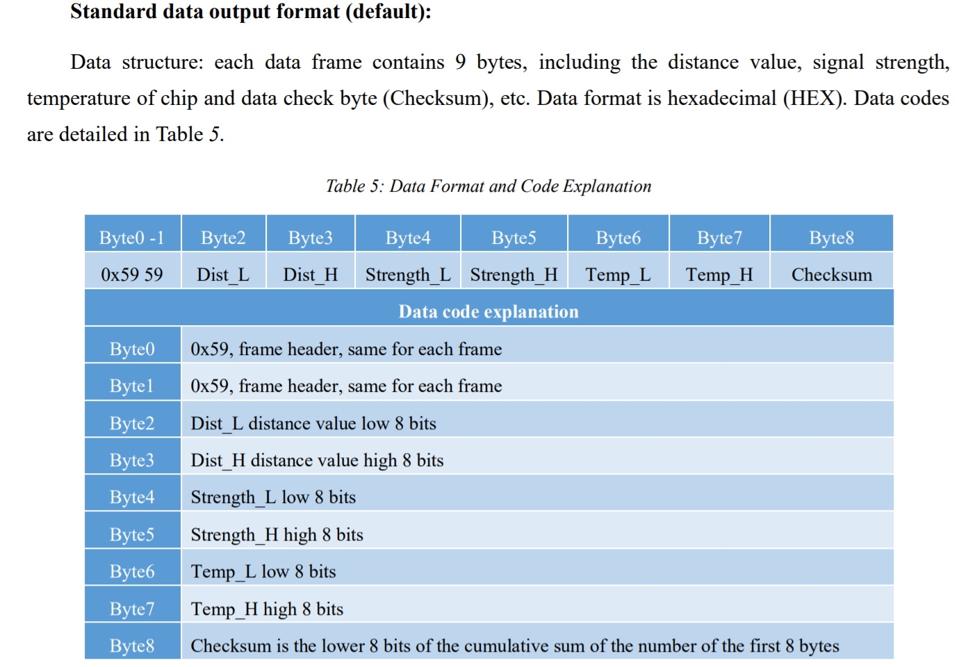
What is shown in PST is:
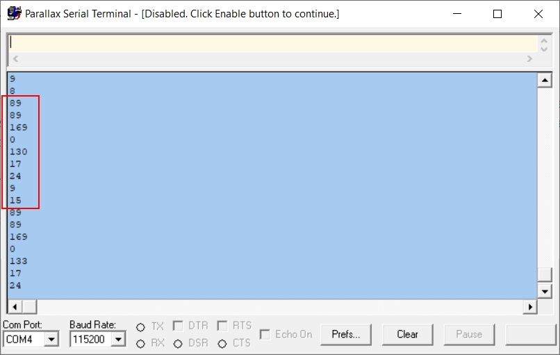
$59 = decimal 89 so the frame header is correct. The other data looks OK and the number of bytes is correct.
Prior to shuffling incoming data through a byte array, my first step was to to try and identify the frame header. Any suggestions as to how to do this would be appreciated. I've tried:
a) Making a string equal to "89" and using STRCOMP to compare it to incoming bytes
b) Making a string equal to "89" and using STRCOMP to compare it to incoming bytes made into a string by Numbers.spin
c) Comparing 89 with incoming bytes as decimal numbers
d) Similar to the above but with hex
e) Comparing the incoming bytes to %01011001 ($59)
Thanks,
Hugh
Comments
I wrote test code for the TFMini-S Plus last year, and know I had it working -- but I can't find the adapter cable so I cannot run this code again after refreshing it for my new methods in jm_fullduplexserial.spin. Still, you may find this helpful.
Look in gps NMEA decoder spin code example:
https://forums.parallax.com/discussion/107629/gps-decoding-of-nema-strings
We have used a similar sensor. Here is one approach in Flow Chart format :
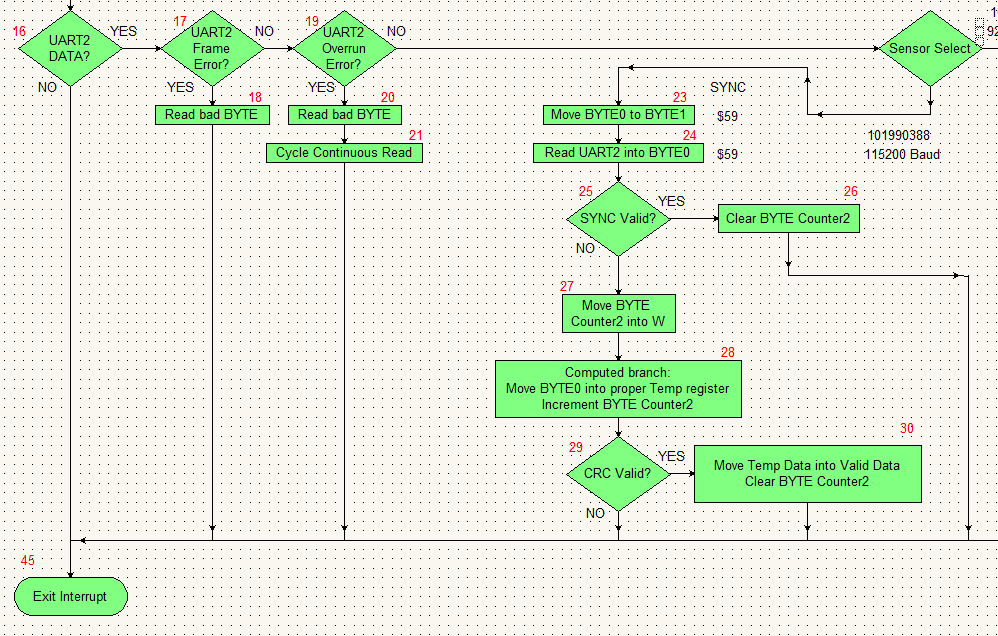
Keep in mind this was written for a PIC micro in direct Assembly, so things like "W" refer directly to a register
The red numbers outside of each flow box indicate the Node.
BYTE0 to BYTE8 are defined variable buffer space
The general flow:
1) The PIC UART receives one character at a time and enters the flow at Node #16(top left) - Each received BYTE generates an interrupt
2) Assuming there are no Framing Errors (i.e. stop bit does not align, etc.) and there are no Over run errors then the flow ends up at Node #23
3) Node #23 and #24 form a tiny little FIFO (First In First Out) for the incoming data BYTES
4) Node #25 simply looks at BYTE0 and BYTE1, if both values are the same and both values are $59 then a valid SYNC has been detected. As a result an incoming BYTE counter is cleared
5) The next DATA BYTE received should fail the sync detect and move the BYTE counter into W in preparation for a computed branch. (i.e. whatever is in W are the number of lines skipped in the computed branch)
6) Step 5 above properly positions the incoming data into the respective BYTES....
Note: CRC variable defined as a BYTE
CRC = BYTE0 + BYTE1+ BYTE2+ BYTE3+ BYTE4+ BYTE5+ BYTE6+ BYTE7
Note: BYTE0 and BYTE1 are constantly flipping around as new data arrives and are not allocated based on the computed branch.
Since we know a valid sync is 0x59, 0x59 we can compute the CRC portion of BYTE0 and BYTE1 into one number 0xB2 instead
CRC = 0xB2 + BYTE2+ BYTE3+ BYTE4+ BYTE5+ BYTE6+ BYTE7
if the CRC check is valid (BYTE8 should equal the computed CRC) in step 6, then and only then are the respective BYTES written as a 'shadow register' for other parts of the program to access i.e.
DIST = BYTE3256+BYTE2
STRENGTH = BYTE5256+BYTE4
TEMP = BYTE7*256+BYTE6
If the CRC does not align, then ALL BYTE data is ignored. Only a valid Packet will make it through to the shadow registers
Note: Any failure off of Node17, Node19, or BYTE count over flow will clear BYTE0 to BYTE9
Brilliant. Thank you! Not only is it working but I learnt a few things, too.")