Okay, I do remember a ring drawing some years back. It might have been for the Prop1 even.
So, at sysclock of 400 MHz the VCO stage delays are just 178.6 ps, right? How is that wired to provide adjustable delays in every stage?
@evanh said:
So, at sysclock of 400 MHz the VCO stage delays are just 178.6 ps, right? How is that wired to provide adjustable delays in every stage?
Yeah, you're right.
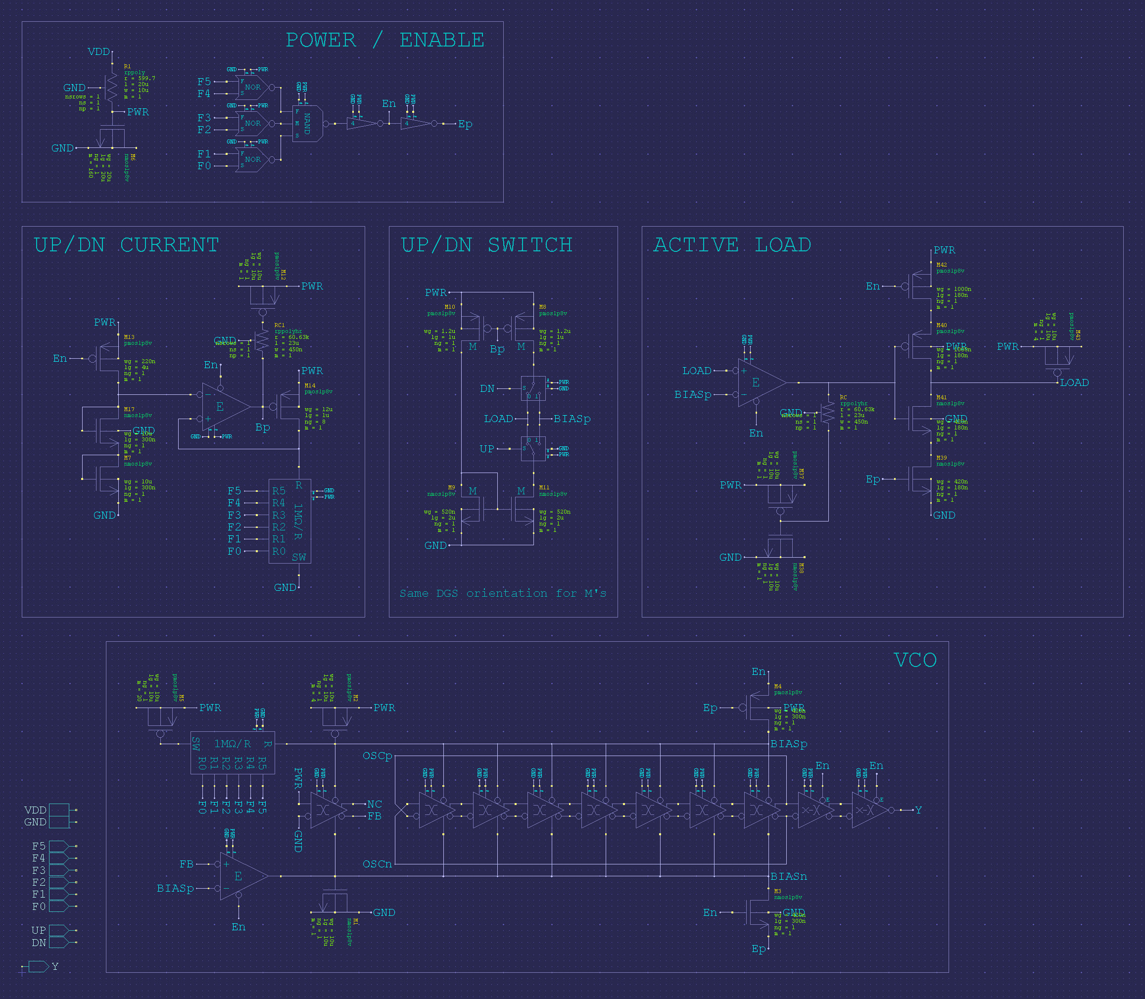
The adjustment of the amount of delay each stage will impose to the propagation of the waveform is controlled by the amount of bias current provided by the bias generator.
As for biasing, all seven stages are wired in parallel, so, when bias current is increased (or "pumped-up"), the rate of charging/discharging of the capacitances of the fets that comprises each of the inverters will increase, thus, the delay decreases, and the VCO frequency increases.
Inverselly, when bias current is decreased (or "pumped-down"), the rate of charging/discharging of the capacitances of the fets will also decrease, thus, the delay increases, and the VCO frequency decreases.
For short: more bias current resulting higher frequency; less bias current resulting lower frequency.
And, sure, if the bias current remains stable, so does the frequency.
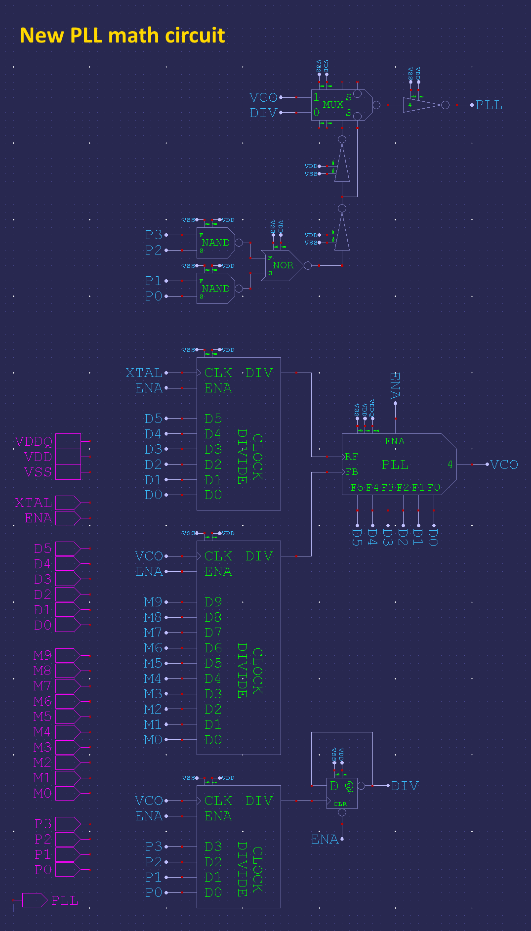
Hmm, I guess there isn't a viewable schematic for that. Chip posted a schematic for the "PLL math circuit" some years back, which had a single block for most of the PLL, including VCO and PFD and a 6-bit control of something with matching of crystal divider control.
I'm guessing that block is a licenced library macro. A black box we don't get to see inside of.
(after a little 2.5 hours "snooze", for the sake of "sanity")...
Yeah, the following block, cropped from the one you've posted, contains the part of the circuit where the "magic" takes place.
The PFD, bias generator and ring oscillator are inside it.
Note the presence of VDDQ (V2831, in this case), which feds the bias generator. The absence of any other external I/O, related to the block, is another clue of its function.
At the former view, XTAL is the resulting waveform of the crystal/clock oscillator circuit, VDD-domain-wise, thus the absence of any reference to XI, XO, or its other controls.
RF and FB transports the frequencies the PFD constantly compares, trying to match them, both in Phase and Frequency.
The more often the comparison occurs, the better ("finner") the control the PFD will exert over the bias generator, hence, less opportunity any small "instantaneous jitter wanderings" will have to deviate the tracking of both frequencies.
Any "pileing, or accumulation" can only be observed by superposing many instances, one over another, centered around an "imaginary, zero-jitter locus", as shown at post #354.
The resulting DOWN and UP, the bias generator, and the ring oscillator themselves are also not shown.
The remaining circuitsoutstanding blocks and logic circuits are present at the image you've posted above.
Since the "20.67 MHz" VCO frequency you've selected and the original 20.0000 MHz crystal that should be connected between XI and XO (supposing you're still using it) are really closer, I would like to explore the subject a little by crafting some more graphical analisys, trying to understand how and when the PFD action is more likelly to interfere, and push the bias correction to its limits.
Perhaps it'll be usefull to understand it a little more, in order to be able to preview the maximum expected jitter (in fS/nS), and also the timeframe of its occurrence.
Would you mind sharing the configuration bits you've selected (hubset command description), responsible for the setup that resulted in the image shown at post #354?
I didn't write it down so, a quick test, looks like it was D=30 M=31 P=1. Mode value of $01741efb
EDIT: Yeah, I've still got some of the code in there. I've forced DIVD >= 3 so it would more likely produce unstable combinations. Err, no, even that was overridden. Looks like I did very little experimenting with it since. Here's the source code selecting just that combination.
I will use them, while trying to keep with the Olympic Games (hoping to keep busy enough, in order to don't fall asleep, seated at the chair like an abandoned sack of potatoes)
All wrinkled and squishy. That's an attractive trait for an elephant.
You've just got a winning bet!
Sometimes, due to bad blood circulation, my legs looks like elephant ones. The footprints are still human-alike, but the rest resembles a "Sequoiadendron giganteum".
Thanks God, I don't need to rely on my toes, in order to operate the keyboard, nor the mouse...
Here's a link to the most recent VCO schematic I was able to find, as posted by Chip (at the time. Wow, near five years ago). The seven stages are clearly noticeable.
There are to many gems, burried into those threads. It's like mining for just that one almost lost paragraph, while exploring a huge pile of books, from of a whole library.
Now you can see why the waveforms I craft are showing only one inversion, just where the non-inverted output of the last differential delay stage connects to the inverted input of the first stage (and, sure, vice-versa for the inverted output), closing the ring.
I believe it's easier to the eyes to show only the non-inverted ouput (complimentary waveforms always looks like data buses (at least to me), unless the graphic app used to craft the graph is able to apply bold lines to the non-inverted output (the one I use doesn't)).
The staircase-look of the waveforms turns it easy to remember there is a delay involved in the propagation of the transitions, from each stage to the next one. Only the ring-closure is taken as being "almost" instantaneous.
I first thought I'd completely missed that analogue chip topic but searching for my name I do find some posts in the middle pages. I must have been busy at work though. My posts aren't really engaging with the technical talk. And I don't remember ever even seeing the PLL schematics.
Seems a lot of this thread recently is mostly about VCO/PLL internals and behavior. Moderators, it might make sense to split some of this discussion off into another thread, perhaps starting from my own post which seems to be what triggered the side track/diversion into this area.
@rogloh said:
Seems a lot of this thread recently is mostly about VCO/PLL internals and behavior. Moderators, it might make sense to split some of this discussion off into another thread, perhaps starting from my own post which seems to be what triggered the side track/diversion into this area.
During today's Zoom meeting I asked Chip some questions about the the way the streamers operate, when programmed to output DVI video and clocking information.
If I got it right, there are means to achieve kind of a "hardware-assisted" zoom, where the nco rollover can be reprogrammed during each and every horizontal line, in order to get the same RGB information reiterated thru the TMDS encoders more than once, thus outputing the same basic pixel color information in each channel, while keeping the running disparity up to date, according to the appropriate encoding rules.
This means that, e.g., by changing the following nco setup from:
setxfrq ##$0CCCCCCC+1 'set streamer freq to 1/10th clk
to:
setxfrq ##$06666666+1 'set streamer freq to 1/20th clk
will effectivelly force the TMDS encoder to operate two times over the same R, G orand B values it gots from the hub, before the nco rollover forces it to grab another long from the hub (<-too woody-alike).
In principle, the same is valid for any multiple of 10, but, sure there is a limit, imposed by the number of pixels that would fit within a horizontal line.
Note that the above only aplies to the lines, thus, one needs to scan the same line just as many times as the horizontal pixels get multiplied, in order to get the appropriate proportion, but, sure, it's just optional, so, different scalling effects can be attainned, both horizontally, and vertically.
Also note that, without using extra memory, the same color information will be used every time, thus not too many effects are expected, besides scalling, without involving some extra routines, in order to, e.g., reload the palete during the retrace period, but it don't blocks creativity.
This opens the possibility of achieving, e. g., text, or sprites coexistence with pictures, even live images, such as signal traces from oscilloscope-modes, or logic analyzers, while preserving the amount of used ram at a minimum level. Also the bandwidth usage, when accessing external memory (for, e.g., text, or sprites) can be lowered.
Some experiment needs to be made, to ensure that proper TMDS clocking is effectivelly presented to the respective pin-pair, but that's the easiest part of it, because, in case it's affected, there are many ways of programming the pins to act as if they would be receiving the proper information from the streamer; the solelly concern would be about mannaging them to be in phase whith the expected waveforms.
Beyound this, two streamers can be programmed to overlap on the same pin-group, and have only the RGB lanes switched on-the-fly, as required, but, in this case, the running disparity consistency cannot be ensured without extra processing (aka: more routines), in order to avoid pixel artifacts at the transitionsregion. A possible advantage of overlaping streamers is that one don't needs to worry about the clock pins, if at least one of them is kept outputing the right frequency, during each horizontal line. Sure, by opting to use two streamers, one needs to ensure they're kept in strict sync, or garbage will pop-up.
Sounds interesting Henrique. So if I understand what you are saying is right, the streamer can operate at a different feed rate to the TMDS code outputs and you can horizontally double pixels this way? It would be good to test that sometime. I didn't expect this was possible.
For vertical lines I do have line doubling in my driver and this is handy in some cases. Though this is either single lines or double lines, not line tripled, quadrupled,... etc.
Note that I also have a transparent/sprite mode, where the scan line buffer can be dynamically fed by other COGs outside the video driver, so it can be potentially mixed from multiple sources such as text driver COGs, graphics/sprite COGs, etc. This is the method Wuerfel_21 used with my driver for her P2 video games.
I've not looked at overlapping streamers sharing video output pins from multiple COGs (a bit like we used to do on the P1), so perhaps that could be useful for something. It's likely a logical OR condition on the pin outputs which may constrain what is actually possible there.
@rogloh said:
Note that I also have a transparent/sprite mode, where the scan line buffer can be dynamically fed by other COGs outside the video driver, so it can be potentially mixed from multiple sources such as text driver COGs, graphics/sprite COGs, etc. This is the method Wuerfel_21 used with my driver for her P2 video games.
I actually use the normal bitmap modes with really short wrapping (or in case of the JET compatibility driver, single-line bitmaps and a ring buffer of region structs). The passthrough modes can't do pixel doubling.
If properly set, and controlled, this method will cause no interference between any number of different streamers, while they yield onto the same internal bus lines, despite their wired-or nature.
There are only some basic rules that need to be respected, for it to produce the expected results.
The first rule is someway "electrical": there should have no more than one streamer actively driving any of the eight bus lines involved, unless, of course, they "avoid" driving "ones", at the same time any other can be driving zeros onto that line.
This rule can be violated without causing any harm, of any kind (e.g. destructive effects); if properly done, the line under question will present the effective wired-or result of the logic operation, over the entire electrical bus comprised between each one of the involved cogs corresponding OUT bits, and their equivalent connections at the pad ring.
In case it's improperly done, or miscontrolled, the worse outcome one should ever experience is a wrong result, that can be "rubered out" any time, by analizing the outcome, either thru an instrument connected to the output pin under question, or, if it's not totally possible due some other restrainning condition, by any other Cog, acttivelly "sniffing" the resulting "wired-or" contents.
I use to think in it as a "voyeur mode", just for fun .
The second rule is specific to the case of DVI signaling (or any other TMDS protocol): each and every singular of the non-clock lines effectively carries a "history" of all past transactions "imprinted" over it, in the form of a "running disparity", that has specific "reset" (or "restart") and "calculation" mechanisms.
So, if the running disparity is not kept accordingly, the just-processed "code word", and all the subsequent ones will be affected, until properlly restarted.
In order to properlly "violate" that rule, everyone of the involved Cog's-connected Streamers need to restart the specific line(s) at the same time, with the same data being processed thereon, but only be allowed to become the solelly driver when its particular contents "diverge" from the other ones.
When it's done with that part of the task under its "exclusive" control, it needs to be muted, either by becoming an input-only lane (for the Cog or Streamer to be muted), or by driving zeros, literally mode, unnencoded when done by a Streamer, or simply by means of an OUT, forwarding zeros at the appropriate positions.
The Olympics Games made me think about that rule as some kind of "many by many, one at a time, too many meters relay run", where the baston "can", or "must" change color between passings, by forcefully agreeing to the rules.
Other way I use to think about "running disparity" is looking at it as a form of survivance-rule, when trying to "live" at the realm of Queen of Hearts, in Lewis Carrol's "Alice's Adventures in Wonderland".
Another sound example of it can be thought as a form of the always-rebornt "Agent Smith", on "Matrix".
Mankind insanity has no limits; why not impose it to logic signalling too...
Anyway (but respectfully), all of it did started under the blesses of "Big Bluer's", and then was applyed manywere, anywere, everywere. Too late to complain.
P.S. A TMDS-wise way to "mute" a Streamer is "forcing" it to resync with the running stream(s) of any other(s) connected to the same lane, but this method can be proven hard to achieve (in terms of total thought-energy consumed/sweat produced, versus achieved results/rewards), when the contents of the lane under question are variable, or someway "unpredictable".
Classical cases are overlaying subtitles, or PiP images, notably dynamic content.
Anyway, if something can be digitized, and passed thru a buffer, anyone reading such buffer contents, from the beggining, shoud agree with its contents.
Any "shimmy" at the resulting image(s) can be always attributed to poor contents-tracking.
Hardware assisted zoom is a good way to improve the visual contents of screens, without consuming too much memory.
Otherwise blank areas can be filled with thermometer-alike bar graphs, with dinamically programmable born and extintion, from either direction.
The displacements at the vertical axis would preserve the finest granularity, as provided by sysclk, and consumes the same memory footprint, as any other zooming strategy.
At the horizontal, things will move a bit coarser, but with a more "natural look", only depending on the chosen zoom factor.
Since it can be started/stoped on-the-fly, logarithm horizontal scaling will bennefit from it. Left/right (or its reverse) arrows will also enjoy some snug fit.
I did horizontal/vertical zoom in my displaylisted driver (still work in progress - all my time is now consumed by robotic project - also using a P2).
The display list entry tells the cog
from where it has to get data for the line
what is this line color depth (0/1/2/4/8 bpp - 0 bpp displays a constant color line without using any display data)
what is the line mode (text or graphics)
what font line# it is if in the text mode
what is the pixel horizontal zoom (1/2/4x and 8x - 8x is available only in if 8bpp )
Vertical zoom can be then easy achieved using the same data start address for several lines. There is a "repeat" command implemented where one DL entry can tell the cog how many lines it has to repeat until it adds the offset to the next line (which means you need only several longs to describe all the screen area)
The horizontal zoom is calculated in the cog on the fly while displaying the line.
The displacements at the vertical axis would preserve the finest granularity, as provided by sysclk, and consumes the same memory footprint, as any other zooming strategy.
A very good idea - fine diagonal lines or fine scrolling at the coarse resolution.
As @rogloh did, you're another responsible for throwing a big problem, just in front of my eyes, and I have only two ways for dealing with this kind of situation:
faking I'd totally missed it, and just keep living, normally, as if nothing did happened, at all (impossible );
tacking my pain-prone, "Sitting Bull"-style muscles to this chair, fixing my glassy eyes on this ever-wearing SyncMaster 794MB Plus, and pass the next few days, deeply sunk at it (very likelly );
Too much coffee taken, by the last two years (lying; it's a lifetime addiction); a bit more will don't cause any harm...
(JIT) Ah, thanks for all the p2asm work (spin2 too, of course); when it comes to C (wichever it is), I'm just a Moe (Bart-Simpson-style). Hate to feel so dumb, but can't get any comfort, appart from the bare-metal.
Pik,
I have looked at that before. I keep getting put off by the display mode setting.
I know you can't spend any time on it right now but it needs a pretty big redesign in that area, partly to declutter but also to entirely remove the "mode" number mechanism when requesting a display mode. The API should provide for a parameter based modeset, or at the very least just pass a structure of the required timings to the modeset routine.
Here's my first effort in that direction. It's still in constants form but the list parameters gives an idea of what can be hidden/calculated.
Let me know if any of these modes don't work with your monitors.
PS: Dynamically setting the sysclock frequency, with a HUBSET, is easy to compute now. There is example code for selecting optimal mult/div components for the mode word. It's not yet in Spin source form but I have converted the original to integers in C, so it won't be hard to port over to Spin.
@evanh said:
Pik,
I have looked at that before. I keep getting put off by the display mode setting.
I know you can't spend any time on it right now but it needs a pretty big redesign in that area, partly to declutter but also to entirely remove the "mode" number mechanism when requesting a display mode. The API should provide for a parameter based modeset, or at the very least just pass a structure of the required timings to the modeset routine.
Here's my first effort in that direction. It's still in constants form but the list parameters gives an idea of what can be hidden/calculated.
Let me know if any of these modes don't work with your monitors.
EDIT: small code update
There is a plan to add a "mode 999" (it can not actually be a "999" as it is already occupied) which is what you described: to pass a timing structure to the driver, then select this mode. As it is planned, this is not a major redesign. There is a timings table in the code:
As you can see, there are only 8 entries for 8 different video modes. The rest of bits in the mode # determines horizontal and vertical zoom, text or graphics and color depth.
There is even "timings999" entry added for this purpose. Setmode method gets these timings from this table and sets Spin variable block according to these. Then, every frame, this table is read from hub to cog, allowing mode change on the fly.
This is
long timings[16] 'graphic mode timings
where these longs are
''--------- timings
' 0 m_bs - before sync, 16 80
' 1 m_sn - sync 80 160
' 2 m_bv - before visible 20 84
' 3 m_vi - visible 1024 816
' 4 m_border - left and right borders 112 8
' 5 m_lut1 - pixels per char 8 8
' 6 i_vborder - up and down border 48 8
' 7 i_upporch - up non visible 16 8
' 8 i_vsync - vsync 16 12
' 9 i_downporch - down non visible 16 8
'10 mode #
'11 cpl - character per line
'12 scanlines #
'13 clock
'14 hubset value for clock settings
If you change something here, the change will be introduced in the next frame (except clock/hubset value) without any function calling or checking if it is good. This means if I want to try your settings, I can. I have to add your code as a spin method, let it compute all values I need, then put these values into timings table, and recompute a display list.
The conclusion is:
the mode # will remain as is
the DL generator will be updated
there will be a magic mode number which will get a description from the user and then compute the rest and set the requested mode.
There is also a simpler HDMI driver which I derived from this for my robotic project. What I needed was a driver for 5" 800x480 HDMI LCD screen, mounted vertically to the robot. So I got my driver, defined one set of timings at 285 MHz and used 2x horizontal and vertical zoom @ 8bpp. This gave me 240x400 resolution and 96 kB buffer size. 2x2 zoom makes 8x16 font readable on this 5" screen. The cog RAM occupied is about 100 longs instead of over 400 in the full version.
' bf.hs, hs, bf.vis visible, lr bord, pixel, ud bord, up p., vsync, down p., mode, cpl, scanlines, clock, hubset total vis lines
timings000 long 48, 32, 80, 800, 0, 8, 0 , 3, 7, 6, 0, 100, 480, 285000000, %1_110000__11_0110_1100__1111_1011, 480
The robot started to move today - it displays parameters on its screen which makes debugging easier. The P2 based board is its main brain, controlling BLDC motors, light sources, fans, ultrasonic proximity sensors, measuring battery voltage and getting commands from SBUS remote control receiver. There are also 2 L515 cameras controlled by RPis - the processed lidar data go to the P2 via UART. Near all pins used I have now to teach it to move on its own. The robot will disinfect the air in the COVID hospital using a UVC light source. All time and energy is now consumed by this.
I'd love to know if my example works with your monitors. Note: There is more than one set of parameters to try out. And of course you're welcome to create your own sets.
Eg:
_clkfreq = 330_000_000 'must be at least 250 MHz for DVI/HDMI
hgraph = 640 ' videoarray X, <= "hvis"
vgraph = 64 ' videoarray Y, <= "vvis"
hvis = 1024 ' resolution X
vvis = 576 ' resolution Y
vfreq = 50 ' preferred refresh rate
@pik33 said:
The robot started to move today - it displays parameters on its screen which makes debugging easier. The P2 based board is its main brain, controlling BLDC motors, light sources, fans, ultrasonic proximity sensors, measuring battery voltage and getting commands from SBUS remote control receiver. There are also 2 L515 cameras controlled by RPis - the processed lidar data go to the P2 via UART. Near all pins used I have now to learn it to move on its own. The robot will disinfect the air in the COVID hospital using a UVC light source. All time and energy is now consumed by this.
That's a big job! There must be others coding the vision side at least.
I am the only coder in this project We have 4 persons in this robot's construction team, 2 mechanical engineers, 1 electronic engineer and 1 electronic and IT engineer (that's me). The project is big, but we have the robot moving now.


Comments
Okay, I do remember a ring drawing some years back. It might have been for the Prop1 even.
So, at sysclock of 400 MHz the VCO stage delays are just 178.6 ps, right? How is that wired to provide adjustable delays in every stage?
Yeah, you're right.
The adjustment of the amount of delay each stage will impose to the propagation of the waveform is controlled by the amount of bias current provided by the bias generator.
As for biasing, all seven stages are wired in parallel, so, when bias current is increased (or "pumped-up"), the rate of charging/discharging of the capacitances of the fets that comprises each of the inverters will increase, thus, the delay decreases, and the VCO frequency increases.
Inverselly, when bias current is decreased (or "pumped-down"), the rate of charging/discharging of the capacitances of the fets will also decrease, thus, the delay increases, and the VCO frequency decreases.
For short: more bias current resulting higher frequency; less bias current resulting lower frequency.
And, sure, if the bias current remains stable, so does the frequency.
Hmm, I guess there isn't a viewable schematic for that. Chip posted a schematic for the "PLL math circuit" some years back, which had a single block for most of the PLL, including VCO and PFD and a 6-bit control of something with matching of crystal divider control.
I'm guessing that block is a licenced library macro. A black box we don't get to see inside of.
(after a little 2.5 hours "snooze", for the sake of "sanity")...
Yeah, the following block, cropped from the one you've posted, contains the part of the circuit where the "magic" takes place.
The PFD, bias generator and ring oscillator are inside it.
Note the presence of VDDQ (V2831, in this case), which feds the bias generator. The absence of any other external I/O, related to the block, is another clue of its function.
At the former view, XTAL is the resulting waveform of the crystal/clock oscillator circuit, VDD-domain-wise, thus the absence of any reference to XI, XO, or its other controls.
RF and FB transports the frequencies the PFD constantly compares, trying to match them, both in Phase and Frequency.
The more often the comparison occurs, the better ("finner") the control the PFD will exert over the bias generator, hence, less opportunity any small "instantaneous jitter wanderings" will have to deviate the tracking of both frequencies.
Any "pileing, or accumulation" can only be observed by superposing many instances, one over another, centered around an "imaginary, zero-jitter locus", as shown at post #354.
The resulting DOWN and UP, the bias generator, and the ring oscillator themselves are also not shown.
The remaining circuits outstanding blocks and logic circuits are present at the image you've posted above.
Hi evanh
Since the "20.67 MHz" VCO frequency you've selected and the original 20.0000 MHz crystal that should be connected between XI and XO (supposing you're still using it) are really closer, I would like to explore the subject a little by crafting some more graphical analisys, trying to understand how and when the PFD action is more likelly to interfere, and push the bias correction to its limits.
Perhaps it'll be usefull to understand it a little more, in order to be able to preview the maximum expected jitter (in fS/nS), and also the timeframe of its occurrence.
Would you mind sharing the configuration bits you've selected (hubset command description), responsible for the setup that resulted in the image shown at post #354?
I didn't write it down so, a quick test, looks like it was D=30 M=31 P=1. Mode value of $01741efb
EDIT: Yeah, I've still got some of the code in there. I've forced DIVD >= 3 so it would more likely produce unstable combinations. Err, no, even that was overridden. Looks like I did very little experimenting with it since. Here's the source code selecting just that combination.
Thanks for the prompt answer!
I will use them, while trying to keep with the Olympic Games (hoping to keep busy enough, in order to don't fall asleep, seated at the chair like an abandoned sack of potatoes)
And here it is as I was first using it to step through frequencies (Scope probe is attached to pin P40):
All wrinkled and squishy. That's an attractive trait for an elephant.
You've just got a winning bet!
Sometimes, due to bad blood circulation, my legs looks like elephant ones. The footprints are still human-alike, but the rest resembles a "Sequoiadendron giganteum".
Thanks God, I don't need to rely on my toes, in order to operate the keyboard, nor the mouse...
Here's a link to the most recent VCO schematic I was able to find, as posted by Chip (at the time. Wow, near five years ago). The seven stages are clearly noticeable.
https://forums.parallax.com/discussion/comment/1393146/#Comment_1393146
There are to many gems, burried into those threads. It's like mining for just that one almost lost paragraph, while exploring a huge pile of books, from of a whole library.
Now you can see why the waveforms I craft are showing only one inversion, just where the non-inverted output of the last differential delay stage connects to the inverted input of the first stage (and, sure, vice-versa for the inverted output), closing the ring.
I believe it's easier to the eyes to show only the non-inverted ouput (complimentary waveforms always looks like data buses (at least to me), unless the graphic app used to craft the graph is able to apply bold lines to the non-inverted output (the one I use doesn't)).
The staircase-look of the waveforms turns it easy to remember there is a delay involved in the propagation of the transitions, from each stage to the next one. Only the ring-closure is taken as being "almost" instantaneous.
Wow! Thank you Henrique.
I first thought I'd completely missed that analogue chip topic but searching for my name I do find some posts in the middle pages. I must have been busy at work though. My posts aren't really engaging with the technical talk. And I don't remember ever even seeing the PLL schematics.
You're welcome!
Don't talk about your posts contents, or I will start to talk about mine (messy english, and, often, to messy contents)
The one I posted, is the new version. I also found the "old" one, whose schematic was completelly different, and didn't worked, as expected:
From that post:
https://forums.parallax.com/discussion/comment/1392089/#Comment_1392089
Seems a lot of this thread recently is mostly about VCO/PLL internals and behavior. Moderators, it might make sense to split some of this discussion off into another thread, perhaps starting from my own post which seems to be what triggered the side track/diversion into this area.
https://forums.parallax.com/discussion/comment/1525890/#Comment_1525890
Maybe it could be called something like "P2 VCO/PLL behavior"
Looks like Chip updated it again - https://forums.parallax.com/discussion/comment/1393213/#Comment_1393213
Yes, that's the right post to cut from. Lol, every post since then has been about the PLL.
Hi rogloh
During today's Zoom meeting I asked Chip some questions about the the way the streamers operate, when programmed to output DVI video and clocking information.
If I got it right, there are means to achieve kind of a "hardware-assisted" zoom, where the nco rollover can be reprogrammed during each and every horizontal line, in order to get the same RGB information reiterated thru the TMDS encoders more than once, thus outputing the same basic pixel color information in each channel, while keeping the running disparity up to date, according to the appropriate encoding rules.
This means that, e.g., by changing the following nco setup from:
setxfrq ##$0CCCCCCC+1 'set streamer freq to 1/10th clkto:
setxfrq ##$06666666+1 'set streamer freq to 1/20th clkwill effectivelly force the TMDS encoder to operate two times over the same R, G or and B values it gots from the hub, before the nco rollover forces it to grab another long from the hub (<-too woody-alike).
In principle, the same is valid for any multiple of 10, but, sure there is a limit, imposed by the number of pixels that would fit within a horizontal line.
Note that the above only aplies to the lines, thus, one needs to scan the same line just as many times as the horizontal pixels get multiplied, in order to get the appropriate proportion, but, sure, it's just optional, so, different scalling effects can be attainned, both horizontally, and vertically.
Also note that, without using extra memory, the same color information will be used every time, thus not too many effects are expected, besides scalling, without involving some extra routines, in order to, e.g., reload the palete during the retrace period, but it don't blocks creativity.
This opens the possibility of achieving, e. g., text, or sprites coexistence with pictures, even live images, such as signal traces from oscilloscope-modes, or logic analyzers, while preserving the amount of used ram at a minimum level. Also the bandwidth usage, when accessing external memory (for, e.g., text, or sprites) can be lowered.
Some experiment needs to be made, to ensure that proper TMDS clocking is effectivelly presented to the respective pin-pair, but that's the easiest part of it, because, in case it's affected, there are many ways of programming the pins to act as if they would be receiving the proper information from the streamer; the solelly concern would be about mannaging them to be in phase whith the expected waveforms.
Beyound this, two streamers can be programmed to overlap on the same pin-group, and have only the RGB lanes switched on-the-fly, as required, but, in this case, the running disparity consistency cannot be ensured without extra processing (aka: more routines), in order to avoid pixel artifacts at the transitions region. A possible advantage of overlaping streamers is that one don't needs to worry about the clock pins, if at least one of them is kept outputing the right frequency, during each horizontal line. Sure, by opting to use two streamers, one needs to ensure they're kept in strict sync, or garbage will pop-up.
Hope it helps.
Henrique
Sounds interesting Henrique. So if I understand what you are saying is right, the streamer can operate at a different feed rate to the TMDS code outputs and you can horizontally double pixels this way? It would be good to test that sometime. I didn't expect this was possible.
For vertical lines I do have line doubling in my driver and this is handy in some cases. Though this is either single lines or double lines, not line tripled, quadrupled,... etc.
Note that I also have a transparent/sprite mode, where the scan line buffer can be dynamically fed by other COGs outside the video driver, so it can be potentially mixed from multiple sources such as text driver COGs, graphics/sprite COGs, etc. This is the method Wuerfel_21 used with my driver for her P2 video games.
I've not looked at overlapping streamers sharing video output pins from multiple COGs (a bit like we used to do on the P1), so perhaps that could be useful for something. It's likely a logical OR condition on the pin outputs which may constrain what is actually possible there.
I actually use the normal bitmap modes with really short wrapping (or in case of the JET compatibility driver, single-line bitmaps and a ring buffer of region structs). The passthrough modes can't do pixel doubling.
If properly set, and controlled, this method will cause no interference between any number of different streamers, while they yield onto the same internal bus lines, despite their wired-or nature.
There are only some basic rules that need to be respected, for it to produce the expected results.
The first rule is someway "electrical": there should have no more than one streamer actively driving any of the eight bus lines involved, unless, of course, they "avoid" driving "ones", at the same time any other can be driving zeros onto that line.
This rule can be violated without causing any harm, of any kind (e.g. destructive effects); if properly done, the line under question will present the effective wired-or result of the logic operation, over the entire electrical bus comprised between each one of the involved cogs corresponding OUT bits, and their equivalent connections at the pad ring.
In case it's improperly done, or miscontrolled, the worse outcome one should ever experience is a wrong result, that can be "rubered out" any time, by analizing the outcome, either thru an instrument connected to the output pin under question, or, if it's not totally possible due some other restrainning condition, by any other Cog, acttivelly "sniffing" the resulting "wired-or" contents.
I use to think in it as a "voyeur mode", just for fun .
.
The second rule is specific to the case of DVI signaling (or any other TMDS protocol): each and every singular of the non-clock lines effectively carries a "history" of all past transactions "imprinted" over it, in the form of a "running disparity", that has specific "reset" (or "restart") and "calculation" mechanisms.
So, if the running disparity is not kept accordingly, the just-processed "code word", and all the subsequent ones will be affected, until properlly restarted.
In order to properlly "violate" that rule, everyone of the involved Cog's-connected Streamers need to restart the specific line(s) at the same time, with the same data being processed thereon, but only be allowed to become the solelly driver when its particular contents "diverge" from the other ones.
When it's done with that part of the task under its "exclusive" control, it needs to be muted, either by becoming an input-only lane (for the Cog or Streamer to be muted), or by driving zeros, literally mode, unnencoded when done by a Streamer, or simply by means of an OUT, forwarding zeros at the appropriate positions.
The Olympics Games made me think about that rule as some kind of "many by many, one at a time, too many meters relay run", where the baston "can", or "must" change color between passings, by forcefully agreeing to the rules.
Other way I use to think about "running disparity" is looking at it as a form of survivance-rule, when trying to "live" at the realm of Queen of Hearts, in Lewis Carrol's "Alice's Adventures in Wonderland".
Another sound example of it can be thought as a form of the always-rebornt "Agent Smith", on "Matrix".
Mankind insanity has no limits; why not impose it to logic signalling too...
Anyway (but respectfully), all of it did started under the blesses of "Big Bluer's", and then was applyed manywere, anywere, everywere. Too late to complain.
P.S. A TMDS-wise way to "mute" a Streamer is "forcing" it to resync with the running stream(s) of any other(s) connected to the same lane, but this method can be proven hard to achieve (in terms of total thought-energy consumed/sweat produced, versus achieved results/rewards), when the contents of the lane under question are variable, or someway "unpredictable".
Classical cases are overlaying subtitles, or PiP images, notably dynamic content.
Anyway, if something can be digitized, and passed thru a buffer, anyone reading such buffer contents, from the beggining, shoud agree with its contents.
Any "shimmy" at the resulting image(s) can be always attributed to poor contents-tracking.
Hardware assisted zoom is a good way to improve the visual contents of screens, without consuming too much memory.
Otherwise blank areas can be filled with thermometer-alike bar graphs, with dinamically programmable born and extintion, from either direction.
The displacements at the vertical axis would preserve the finest granularity, as provided by sysclk, and consumes the same memory footprint, as any other zooming strategy.
At the horizontal, things will move a bit coarser, but with a more "natural look", only depending on the chosen zoom factor.
Since it can be started/stoped on-the-fly, logarithm horizontal scaling will bennefit from it. Left/right (or its reverse) arrows will also enjoy some snug fit.
I did horizontal/vertical zoom in my displaylisted driver (still work in progress - all my time is now consumed by robotic project - also using a P2).
The display list entry tells the cog
Vertical zoom can be then easy achieved using the same data start address for several lines. There is a "repeat" command implemented where one DL entry can tell the cog how many lines it has to repeat until it adds the offset to the next line (which means you need only several longs to describe all the screen area)
The horizontal zoom is calculated in the cog on the fly while displaying the line.
The driver's topis is here: https://forums.parallax.com/discussion/173228/a-display-list-is-fun-0-25-working-alpha-available-at-github
A very good idea - fine diagonal lines or fine scrolling at the coarse resolution.
Great work, @pik33!
As @rogloh did, you're another responsible for throwing a big problem, just in front of my eyes, and I have only two ways for dealing with this kind of situation:
faking I'd totally missed it, and just keep living, normally, as if nothing did happened, at all (impossible );
);
tacking my pain-prone, "Sitting Bull"-style muscles to this chair, fixing my glassy eyes on this ever-wearing SyncMaster 794MB Plus, and pass the next few days, deeply sunk at it (very likelly );
);
Too much coffee taken, by the last two years (lying; it's a lifetime addiction); a bit more will don't cause any harm...
(JIT) Ah, thanks for all the p2asm work (spin2 too, of course); when it comes to C (wichever it is), I'm just a Moe (Bart-Simpson-style). Hate to feel so dumb, but can't get any comfort, appart from the bare-metal.
Henrique
Pik,
I have looked at that before. I keep getting put off by the display mode setting.
I know you can't spend any time on it right now but it needs a pretty big redesign in that area, partly to declutter but also to entirely remove the "mode" number mechanism when requesting a display mode. The API should provide for a parameter based modeset, or at the very least just pass a structure of the required timings to the modeset routine.
Here's my first effort in that direction. It's still in constants form but the list parameters gives an idea of what can be hidden/calculated.
Let me know if any of these modes don't work with your monitors.
EDIT: small code update
PS: Dynamically setting the sysclock frequency, with a HUBSET, is easy to compute now. There is example code for selecting optimal mult/div components for the mode word. It's not yet in Spin source form but I have converted the original to integers in C, so it won't be hard to port over to Spin.
static uint32_t div33( uint32_t dividend, uint32_t divisor ) { uint32_t x; __asm { mov x, divisor shr x, #1 add dividend, x qdiv dividend, divisor getqx x } return x; } static uint32_t muldiv65( uint32_t mult1, uint32_t mult2, uint32_t divisor ) { uint32_t x; __asm { qmul mult1, mult2 mov x, divisor shr x, #1 getqx mult1 getqy mult2 add mult1, x wc addx mult2, #0 setq mult2 qdiv mult1, divisor getqx x } return x; } static uint32_t mul2div65( uint16_t mult1, uint16_t mult2, uint32_t mult32, uint32_t divisor ) { uint32_t x; __asm { mul mult1, mult2 mov x, mult1 } return muldiv65( x, mult32, divisor ); } enum { _MINFPFD = 250_000, }; static uint32_t pll_calc( uint32_t targetfreq ) // returns a suitable _clkset() mode value, or 0 for an out-of-bounds result { uint32_t mult, divd, divp, post, Fpfd, Fvco, mode = 0; int32_t error, besterror = _MINFPFD; for( post = 0; post <= 15; post++ ) { divp = post ? post * 2 : 1; for( divd = 64; divd >= 1; divd-- ) { mult = mul2div65( divp, divd, targetfreq, _XTALFREQ ); Fvco = muldiv65( _XTALFREQ, mult, divd ); Fpfd = div33( _XTALFREQ, divd ); if( (Fpfd >= _MINFPFD) && (mult <= 1024) && (Fvco >= 100_000_000) && ((Fvco <= 201_000_000) || (Fvco <= targetfreq + _MINFPFD)) ) { error = abs( (int32_t)(div33( Fvco, divp ) - targetfreq) ); if( error <= besterror ) { mode = 1<<24 | (divd-1)<<18 | (mult-1)<<8 | ((post-1)&0x0f)<<4 | 0x0b; // %CC==%10 %SS==11 besterror = error; } } } } return mode; }There is a plan to add a "mode 999" (it can not actually be a "999" as it is already occupied) which is what you described: to pass a timing structure to the driver, then select this mode. As it is planned, this is not a major redesign. There is a timings table in the code:
As you can see, there are only 8 entries for 8 different video modes. The rest of bits in the mode # determines horizontal and vertical zoom, text or graphics and color depth.
There is even "timings999" entry added for this purpose. Setmode method gets these timings from this table and sets Spin variable block according to these. Then, every frame, this table is read from hub to cog, allowing mode change on the fly.
This is
long timings[16] 'graphic mode timingswhere these longs are
If you change something here, the change will be introduced in the next frame (except clock/hubset value) without any function calling or checking if it is good. This means if I want to try your settings, I can. I have to add your code as a spin method, let it compute all values I need, then put these values into timings table, and recompute a display list.
The conclusion is:
There is also a simpler HDMI driver which I derived from this for my robotic project. What I needed was a driver for 5" 800x480 HDMI LCD screen, mounted vertically to the robot. So I got my driver, defined one set of timings at 285 MHz and used 2x horizontal and vertical zoom @ 8bpp. This gave me 240x400 resolution and 96 kB buffer size. 2x2 zoom makes 8x16 font readable on this 5" screen. The cog RAM occupied is about 100 longs instead of over 400 in the full version.
The file is https://github.com/pik33/ultibo-propeller/blob/main/hng012/hng026r.spin2 ("r" is for a robot)
It still needs cleaning.
The timings table I used in this is:
The robot started to move today - it displays parameters on its screen which makes debugging easier. The P2 based board is its main brain, controlling BLDC motors, light sources, fans, ultrasonic proximity sensors, measuring battery voltage and getting commands from SBUS remote control receiver. There are also 2 L515 cameras controlled by RPis - the processed lidar data go to the P2 via UART. Near all pins used") I have now to teach it to move on its own. The robot will disinfect the air in the COVID hospital using a UVC light source. All time and energy is now consumed by this.
I have now to teach it to move on its own. The robot will disinfect the air in the COVID hospital using a UVC light source. All time and energy is now consumed by this.
I'd love to know if my example works with your monitors. Note: There is more than one set of parameters to try out. And of course you're welcome to create your own sets.
Eg:
_clkfreq = 330_000_000 'must be at least 250 MHz for DVI/HDMI hgraph = 640 ' videoarray X, <= "hvis" vgraph = 64 ' videoarray Y, <= "vvis" hvis = 1024 ' resolution X vvis = 576 ' resolution Y vfreq = 50 ' preferred refresh rateThat's a big job! There must be others coding the vision side at least.
I am the only coder in this project") We have 4 persons in this robot's construction team, 2 mechanical engineers, 1 electronic engineer and 1 electronic and IT engineer (that's me). The project is big, but we have the robot moving now.
We have 4 persons in this robot's construction team, 2 mechanical engineers, 1 electronic engineer and 1 electronic and IT engineer (that's me). The project is big, but we have the robot moving now.
This is my early playing with the L515 depth camera: https://forums.parallax.com/discussion/173529/playing-with-intel-l515-depth-camera#latest
Hmm, I see the BITDAC pin setup is driving between Vdd and Vdd/2 rather than rail-to-rail. Same with Roger's driver. Why is that?