

(New video) KonneX thoughts, comments and questions
 Nix
Posts: 33
Nix
Posts: 33
After demonstrating my KonneX programming system on the Propeller 2 live forum 5th August 2021, it would be good to have some feedback.
Link here:
Low down
KonneX is a zero code programming system that incorporates the ability to create massively parallel programs that will utilise as many CPU cores (or cogs) as is necessary, without the programmer being aware of it.
Conventionally, multi-threaded programming is a pain. The programmer really has to think about the threads and their synchronisation. Most of the time, they won't bother and as a result, most applications will only utilise a single core. It's only for CPU intense programs (like video processing and 3D games) where the programmers will bother.
It is my intention to port this program to Java and simplify the interface as well as the data typing and language, so that it could be used by children. Adding visualisations so that execution paths can be observed.
I think kids will love it. Once you've let go of conventional programming and begin to see it operate like a rail system or delivery system, the whole thing become a lot easier to understand.
There are other features I have incorporated into this system, that are not covered by the demo.
- It is completely human language independent. Language data is stored completely separately from binary library data, allowing anyone to create a language file or translation, without messing with the binary itself.
- It is resilient to updates causing problems. Instructions, once defined and published, cannot be altered. The code (or map) can be altered for bug fixes, but the arguments and exits cannot. If the programmer wishes to add extra functionality to an existing instruction, they must create a new one. As such, when it comes to matching library compatibility, it is only instruction ordinals that are important, not the version. (each instruction has an ordinal value which does not change).
- It is highly portable. So long as the kernel and basic libraries are available, any KonneX program will work.
Comments
I have seen the video. If I understood correctly, the software produces some bytecode from the "blocks".
But how does the processing look like in the microcontroller. Some virtual stack machine, like in Forth?
Written in assembler or compiled C-code?
How do I generate a new block or function?
Can I extend the library myself?
So far the whole thing is still a black box for me, but sounds interesting.
What is your goal? To earn money?
Yes, when compiled, the "map" is very like a 32 bit CISC type byte code. The KonneX kernel reads the code, locates the libraries and the desired instruction.
It works on the principle of virtual CPUs that are created and destroyed as necessary. The virtual CPU has only 5 registers. (A resource register, a data register, stack pointer, program counter and a thread ID.
Assembler
Just create a new one. Define its arguments and exits and code it in the same manner as the demo.
You can extend your own libraries, but not 3rd party libraries. Having said that, you can create your own override libraries and extend functionality that way.
To earn a living would be nice")
Does no one see the advantages of coding for multi-core systems this way?
Hard to say, but there were times when people destroyed steam machines and fought trains.
The concept looks interesting. Is there a proof of concept or something out there that we can download and play with?
i fear, they all fight the same fight. But they are here😊
I have a proof of concept, but it only works on a 68040 machine.
To add....
This is why I became interested in the P2. If there is sufficient interest in this, I will target the P2 as the primary platform.
The reactions from forum mebers are probably not what you might expect from the "typical" outside world. Many of us have grey hair and long beards. Most of us are used to assembler or similar "low level" programming languages.
Choosing a specific programming language is a matter of personal preference and as we all know arguing between programmers about what language to use has often been compared with religious wars.
When I started to develop FPGA designs the common way was to draw schematics with gates, flipflop symbols and wires to connect them. Today, almost nobody still does it that way. Instead, HDL (hardware description languages like VHDL or Verilog) is used. I think, the reason is that a schematic is more clear as long as it fits on one page. But as soon as the whole system becomes more complex, requiring multiple nested design levels it starts to get more and more messy and confusing. The schematics have more off-page symbols than actual functional symbols. So they become "graphical net lists" and can be totally replaced with text without loosing any convenience. Cut/Paste and search/replace is much easier on text than on schematics and if you insert some block in the middle you don't have to manually move away all the crossing wires.
I'm not so concerned with "people". People often reject innovation, lacking the ability to see beyond what they already know. I've already been down that path.
Which is why I came here. A place where innovators congregate. After all, the Propeller is a highly innovative product. I'm sure there are many designers that have rejected the Propeller in favour of the Arduino, simply because the concept bamboozled them.
Those that are here have embraced the Propeller, because they were able to see the possibilities beyond the Arduino, Pi Zero and other single core MCUs.
I think @ManAtWork has summed it up pretty accurately.
Since the Propellers are strange beasts, well, at least not the common crowd, people here usually are the kind who want/need to actually understand how things work internally.
Your concept, while appealing, hides or abstracts these very internals or at least it is how I understand it. It may simplify the programming for some newcomers (you mentioned kids) but once the program (flow) gets more and more complicated it becomes harder to analyze it and make graphical changes to it. If you start to compensate for this and group objects within a new, bigger one then you abstract even more layers and the description of that new block becomes more complicated.
It's much like a block schematic and a detailed one.") .
.
As an example, to gain an understanding of how the TV set works you needed the block schematic. But to fix that same TV set you needed either to swap the faulty module for a working one (easy but not cost effective back in the days and a block schematic would be sufficient) or find what exactly is broken within that module and fix it and for that you needed the detailed schematic. I am from the era when you went the detailed schematic route and the first TV set I fixed was built with vacuum tubes
I have no objections to the graphical representation or design. It is just less convenient for me when programming.
From pictures, it looks a lot like LabVIEW which is, by far, the absolute worst programming environment I've touched. While your programming system may differentiate between function parameters and text boxes, it looks similar enough to scare away a lot of people.
I have occasionally envisioned something like that as a replacement for spreadsheets, but it doesn't seem appropriate to an mcu where i/o is more important than actual processing power.
I think it could be good for prototyping certain things. It reminds me of GNU Radio Companion, which utilizes a similar flowchart style. You attach various sources and sinks together, like a radio transceiver and an audio output, put some filters or math operations in between, add some scope/FFT displays, etc.
It generates some python, IIRC, at the low-level, which you could then use as a basis, or inspiration for a full application, I suppose? I've only ever used it to test something small though, nothing complicated.
I couldn't see using it as a replacement for writing code by hand for a full application though, but as they say, that's just me. It doesn't mean it wouldn't have its place though or that it should deter you from working on it...maybe target the same audience as BlocklyProp?
Cheers,
Jesse
Contrary to Circuitsoft - I have found LabVIEW a good choice as a "programming" language. It depends on the person and the application. I have used the block and wire - and traditional text programming with equal ease. Specifically I have used the block libraries for industrial control applications, and found it much easier than ladder logic languages. I would certainly use it, but just my 2-cents.
Some decades ago I did something called Ladder-Logic. Very crude thing, but I recently found out that it is still in use.
What you are doing with Konnex reminds me of it.
Since I also belong to the group of grey hair and a beard, I like textual representation not graphical, but I do see a lot of potential in your Idea, decoupling the execution flow with buffers and signals.
But to use it on a P2 you will need to include the smart pins witch are basically another 64 execution units, alas just doing a little but effective in parallel to the main 8 execution flows.
Some member here @pjv(?) did a nice scheduling thing on the P1 to run a large number of timed tasks but never published it just gave some examples of how it worked.
You mentioned a 'virtual CPU' to spin up and down to run your byte codes and I can envision how to do that, using one core to dispatch the tasks to different cores, but you will lose the main thing the P1/P2 have to offer and that is determinism.
As soon as you put some sort of task-management around it you loose precision. Because you need to reload the execution engines with new code fragments, absolutely doable on a P1/P2 but it needs some time for task switching, losing precision.
So I am kind of unsure if what you propose makes sense for timing critical applications.
Anyways, keep it coming,
Mike
After a quick search on ladder-logic, yes it seems very similar in some ways.
I understand. I'm almost in the same demographic myself.... but not quite")
I confess, I haven't looked into smart pins yet.
The concept of virtual CPU is just the simplest way I can explain it. It doesn't actually create complex objects that fully emulate a CPU. It's simply a mental representation.
Though I fully accept this to be true of any task management, the system overheads are extremely low (from a handful of clocks to maybe a couple of dozen). What's more time critical tasks can be pushed to the front of the queue.
Thank you
Yes, I have looked at LabVIEW. It's horrible!
Ladder is heavily used world wide for automation inside factories.
The main reason is so that the source code is readable by electricians. They can pick up a the electrical, pneumatic, hydraulic and ladder logic drawings and quickly fault-find the equipment when something like a sensor has been moved out of place.
PS: Ladder's origins go back centuries I suspect. I've seen some very old mecanical relay logic diagrams that look just like it. It predates electronics for sure.
But ... Ladder itself is Smile for data flow. It is what its name says - A logic control methodology.
PLCs do cater for data flow: The ladder has maths operators and data store for displays and SCADA terminals, which usually do the formatting themselves. If larger data sets need processed then there is also options for compiling to function blocks that can be activated from the ladder. It tends to make those function blocks into black boxes. Their I/O is not part of the ladder.
What if you want too much? See here http://eg.bucknell.edu/~cs366/occam.pdf
This shows to me a crossing where the wrong direction was chosen. Before finding acceptance of the concept (a solid application), the T9000 was announced but never saw light as the Universal (nice to have) routing Engine couldn‘t be finished in time. The System died, leaving a lot of garbage behind. Konnex might be able to start over using this concept. If we can use TAQOZ FORTH as the Virtual machine it could be possible to transparently use the implicit multitasking of forth, the cogs in a chip and connect multiple chips to an network of any size. Proof of concept can be done using one instance of Taqoz and a configuration file could determine the finished application as computing power is needed
„The differential equations are transformed into a series of connected blocks“
Sounds familiar to me and could be a joint effort
https://forums.parallax.com/discussion/173479/tacs-an-analog-computer-emulation-a-propeller-tachyon-application#latest
Hi Nix, some thoughts, sorry that I am trying to say them in a direct way, I don't want to be rude:
( I have to admit, that I did not watch the video completely. )
Do you know simulation software like LTSpice? https://www.analog.com/en/design-center/design-tools-and-calculators/ltspice-simulator.html Or Xcos? https://www.scilab.org/software/xcos
The interesting thing is, that nobody prefers text representation of a simulation model. Everybody uses graphical representations there.
I do use LTSpice and I like it very much. I have tried to use graphical programming systems and they have never been better than source text up to now. So what is the difference to programming?
I think one of the very interesting features of a LTSpice representation is, that the connections between blocks are informations/data. So you can see the dependencies between blocks immediately. This is the key for multitasking too: When can a task be done? When the ingredients are available and when the result will be "fresh enough" to be used. The cook can start to make the ice-cream as soon as he has got the eggs and the cream. There has to be some mechanism, that no outdated ice-cream is eaten. So there has to be a freshness tag and a freshness limit. With multitasking it is not essential, when a task is done, but when the result is available.
With LTSpice, you can click onto the line and you will get information about the actual data which would be nice for interactive visual debugging. Some software allows to create new graphical symbols and use colors. Tags and text comments are very helpful and needed. It is really important, that you can create new graphics for new functions, because only then you can see different functions. A npn transistor has a different symbol than a triode valve.
So in your example the line coming from a ping sensor driver block represented by a a graphical ping-symbol would be "distance in mm, as 32bit integer value, every 0,1sec". It does not need any input from other blocks, I think.
Every connection between blocks will be some sort of global variables. At least global to the debugger and to the submodel.
Sub-Blocks and Macroblocks/Submodels
It is essential, that you can have a hierarchical system, where you can zoom in and out, because your monitor will never be big enough. Normally you don't want to see each line of your ping driver code but only the ping sensor symbol and it's output connection. I don't think that the main focus should be the bottom with a graphical representation of every single command. Every possible source-code-block with global variables as in- and outputs should be possible as lowest element.
Not too many innovations! Use an existing language!
You are saying, that you want to create a new bytecode interpreter. I do not at all think, that this is a good idea! It is simply too much work to do. You have to write this interpreter, you have to write its documentation(!!!!). Then you have to write the driver libraries for all the devices that are are available and to write their documentation (!!!!!). This is at least the same amount of work again and needs constant update work. So in my opinion, the output of the graphical system (and the contents of a block?) must be an existing language. My personal preference would be to use a language like C, which is commonly used. (LTspice uses the spice language).
Speed is very important: A compiler, not an interpreter!
If you program a microcontroller, speed can become essential very suddenly. And speed will then decide, if you can do the job at all with a given system or not. So it is a bad idea to start with a new programming system for microcontrollers and use an interpreter. Many applications do not use the speed but the power efficiency of compiled code, which leads to the fact, that your battery can last x times longer compared to interpreted code. Last resort is to use assembler for critical parts. In my opinion, it always better, if you can use one fast high level language instead of being forced to learn/use the second assembler language.
Edit:
Perhaps XOD https://xod.io/ comes somewhat close to what I think would be good. But they do not have the ability to create new symbols. New symbols are really needed, as only with them you can "live within the visual world" without reading all the time. And the data paths should be selectable colors, line-types, having name-tags.
Edit2:
As far as I can see, a graphical programming system does not make programming more easy. But it could perhaps be helpful for sharing and documentation, because it may be helpful that people can get an overview over things.
Regards, Christof
No. Paths can also carry a NULL signal that can simply be used as a trigger.
I can see the resemblance. However KonneX is not a continuous control system. Electronics is a continuous system where, essentially all of it is running continuously and simultaneously.
KonneX is more like a production control system involving logistics. Moving parts around and then executing a process when all the parts are available.
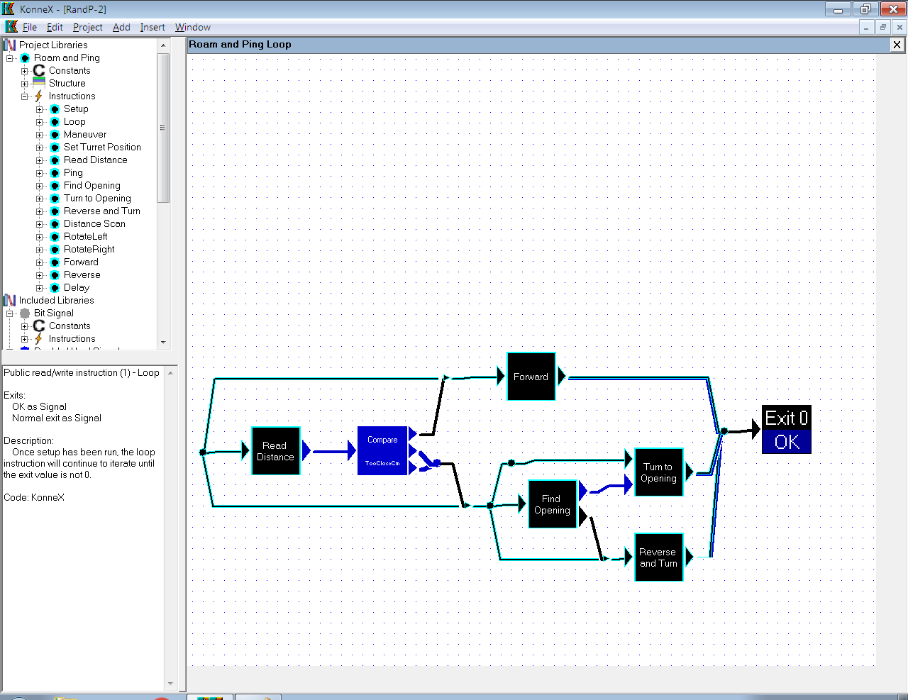
I believe you are inferring that the ping function executes continually. iterating within itself. This is not the case. It only executes when it is called. Consider the "map" in the image at the top of this post, as fulfilling the purpose of the Arduino IDE "loop()" function. The in-built kernel of the Arduino will first execute setup() and then continually call loop(). This is pretty much, doing the same thing. This "map" is executed again, each time it exits.
No. The values in connections are transient and only exist for the purpose of transferring information between blocks. However, they can be handles (pointers) to global values.
Having said that, certain instructions (functions) will pass their input value through. (For example the compare) this is done for convenience. The chances are, that if you are comparing a number, you'll want to use that number later. The purpose of the compare is to change the execution path, so there's no real data to gleaned from the operation. So it simply passes the value through, just in case you want it. In the example above, the value is not wanted and the output simply becomes a NULL trigger to release the buffered "this" handles stored in the buffers above and below the compare.
This will be an intended feature, if development continues.
It is essential. The internal mechanisms demand it. The kernel interprets the bytecode and creates/destroys virtual CPUs on demand. This may sound cumbersome, but it is very fast and not as complex as it may sound. This is the key to the system's parallel processing capability.
See above reply/
It does look similar.
In KonneX, every data type has a specific colour scheme. Border, fill and text colours can all be selected. As you can see in the image above, there are cyan/black; blue and black lines. Each represents a specific data type: cyan/black = the robot handle (this); blue = unsigned word integer; black = NULL signal.
The interface also allows for path renaming, it is just not shown in the video (clicking on a path, input, output, instruction or node offers up a tooltip that provides all the information).
Maybe not for programmers") However, for learning and for those who might want to build their own projects or modify existing projects, they won't need to learn to code.
However, for learning and for those who might want to build their own projects or modify existing projects, they won't need to learn to code.
Thank you NIX for your detailed explanation. I have used this method of graphical programming on many projects, including industrial / automated controls, and it works just fine. There are very few instances where you need nano-second responses, many times if you get a few milli-seconds action it is just fine (it takes actuators, air/pneumatic cylinders, motors, pumps, a lot of time to fully actuate). Certainly any gaming application, timing is really non-critical, same with any educational application. Depending on the application, I sometimes prefer graphical programming. Coding is never easy, easy... it takes work and experience. Go for it.
Hi
I think, graphics are used for the high level view in simulation software, while the detail models are made using text. It is too tiring to use graphics for the details. Graphics can help to get quickly an overview this is the strength. This can only be helpful, if you can see the most relevant information directly. Data types are Not the first thing, if you want to get an overview. The most important information is the physical meaning of the value. So the ping sensor primarily produces "Distance", not "an integer". And you have to have a symbol for a sensor! - It is interesting: schematics use a limited number of symbols. There is a symbol for a diode and a different one for a led. But no difference between germanium and silizium diodes and no difference between colours of leds.
Have you done some estimation, how long you will work on:
1. A new bytecode language. As said, it is too exhausting to write every bit of code with graphics, so a high level language has to be accessible.
2. The docu for the language. If you do not document, nobody can contribute.
3. Examples for the language.
4. Device Drivers. Have you had a look, how many very special assembler instructions P2 has got? Without them, you cannot use the special features of the hardware of P2. As far as I understand, ARM use very many registers to access special functions instead of special instructions. So assembler is used to write device drivers. ( This is a problem not only for your idea, because not so many people want or dare to write assembler. ) But with your new system you have to provide all the device drivers. Plus docu plus examples. I did 3 projects with micropython this year. The first 2 have been a joy, the went really well. The third was a disaster, because the existing device driver (I had checked before, micropython has got a great lot of them available!), written in mycropython was very much too slow. Dead end.
So if you add up the time needed to do everything in addition to your main item, the graphical editor/debugger, then you will see, that you must use an existing base.
https://www.embrio.io/ and https://www.visuino.com/ seem to use the arduino c++ base.
Well, speed of code-interpreters, a simple comparison for P1: The Tachyon wordcode interpreter is quite fast, I don't think it is easy to beat it. LMM-assembler is nearly twice as fast. Assembler loops cached in cog memory can be more than 10 times faster. So I do think, that starting a new development with an interpreter means a big disadvantage settled from start.
The path will be called "Distance". Colours are used so that you instantly know what you can connect to what. Like Coloured wires that define +5V red, +12V yellow.
However, if there were enough demand for it, path re-colouring could be implemented.
Already done.
Already done (mostly)
To be honest, the bytecode language, although not complicated, is horrible to understand at a low level. There are kernel level instructions to cater for thread synchronisation which are an absolute pig to get your head around at bytecode level... hence the graphical system, which does it all for you.
I originally developed this for 68040, so yes, all device drivers will have to be written for P2.
Why? How? The concept is too alien for these systems.
Spin is interpreted bytecode... no one goes on about that
The overheads are relatively tiny.
---SNIP---
Just to add. There is the facility within the software to write native assembler instructions. So, if you wanted a super-fast instruction that would actually be easier to write in assembler, this can be typed in as text. When compiled, the assembler will be called and the raw machine code included in the library / program.
Sorry, I hope, that I don't annoy anybody posting again.
I had to think about another field, where graphics are very clearly leading over text. This is maps.
The best maps, that I know of are topographic maps 1:50.000. They provide very detailed information using symbols: https://www.lgl-bw.de/export/sites/lgl/unsere-themen/Produkte/Galerien/Dokumente/DTK50_Legendenblatt.pdf
On my smartphone, I use the locus map app together with maps from https://www.openandromaps.org/en/legend/elevate-mountain-hike-theme .
They have found a very powerful way to allow zooming in and out maintaining readability. They use some sort of priority level of information.
So to summarize my thoughts, where a graphical system would be preferable over text:
As it comes to maps: i intensively use cmaptools and Would very much like to see such a tool on the Propeller. I‘ll try to document forth words this way and link them using the same mechanism
All good points. Noted.")
I am currently putting together an animation as an introduction to the Konnex system of programming, using rail linked factories as an analogy.
Earlier I did a Early Adopter presentation a bit like yours using TLC ( Touch Logic Control ) which is a parallel visual language in Virtual Breadboard. TLC is a bit like visual ladder logic and it works as a non-programmer language where you click on visual elements in VBB and program by 'doing'. This creates executable storyboards.