

Prop1 Reset Circuitry
 Wingineer19
Posts: 293
Wingineer19
Posts: 293
I've been looking over the reset circuitry for the FLiP and wondering if it can be simplified. This question has no doubt been asked before on this forum, but I can't seem to find an answer.
The BOEn signal is tied low, which enables a weak pull-up on the RESn input so an external resistor isn't necessary. Pulling RESn low of course will trigger a reset.
The schematic shows a high-pass resistor-capacitor (RC) circuit feeding an NPN transistor. The RC circuit produces positive and negative spikes depending upon the transitions of the DTR input signal. Here's a snippet from the schematic:
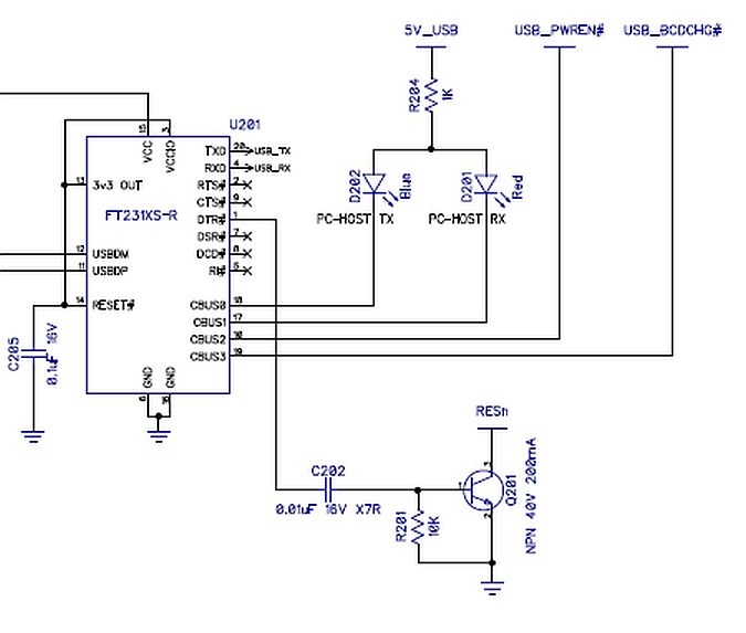
It appears that the positive spike turns on the transistor for about 155 microsecs or so which in turn pulls RESn LO triggering a reset. The transistor then turns off, RESn is pulled HI again, and the Prop enters its bootup sequence. (I'm assuming the negative spike has no adverse effect on the transistor or any other circuitry).
Why can't the resistor, capacitor, and transistor be replaced by a schottky diode? Tie the anode to RESn and the cathode to DTR. If DTR is HI the diode is reverse biased and RESn remains HI. If DTR is LO the diode is forward biased and RESn is pulled to ground triggering a reset. Something like this:
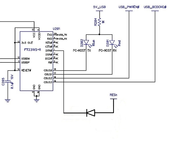
Seems to me it should work provided that DTR can actually swing to GND and can sink the current from the weak pull-up resistor contained within RESn.
I realize there might be some DTR timing tweaks needed to my application code on the PC to reset the Prop so I can then program it, but again it seems like this circuit should work. Thoughts?
Comments
I do not consider the reset circuit of the FLiP module to be complicated. The FLiP module is the culmination of many years of Parallax's efforts to produce useful Propeller products. I rate it as their best ever. You should consider the FLiP's circuitry to be the paradigm of excellence when it comes to Propeller design. Learn from it instead of second-guessing it!
-Phil
Yes, that can work.
Note that you also drop the following features of the original, which may be ok for your use ?
If you want more flexible use than std FLiP reset, you can also connect RES via an AUP1G80 single gate D-FF and a R-C circuit. Or use a small MCU.
That will only reset P1 on a narrow-width pulse on DTR, allowing DTR to be used for other system signaling.
I agree that the FLiP is an impressive device. But I also think that examining and questioning the prior art is essential to technological and societal advancement.
The FLiP is good at what it does. However I would like it to have a little more capability than it has. Like 512KB of EEPROM, and 512KB of SPI SRAM in the "Rampage" configuration so I can run my code in XMM using the Catalina C compiler (which I also like).
I've designed, built, tested, and deployed an add-on board that gives the FLiP this capability. However I'm contemplating that maybe I need to start from scratch and design my own FLiP type module with this circuitry included instead of a kludge type arrangement like I have now. A new module with a clean and efficient design.
Granted, I could just move up to the Prop2 and scope out the modules and boards that already have that desired capability, but I'm not there yet. I really like working with the Prop1.
The reset circuitry is something I'm looking at. The idea I tossed out here would probably work if the default value for DTR was in the Marking (HI) state. It would have to be in that state even if the PC isn't connected (i.e. Stand Alone configuration). If not, then something like the FLiP type reset circuitry would be required otherwise the unit would be stuck in perpetual reset mode. All of that is something I just started researching, so time to dig into the spec sheet for the FT231 for answers.
The system timing circuit is another thing I'm looking at. I can probably program the FT231 to output a 6MHz signal and feed it into the Prop yielding a 96MHz device. That would eliminate the need for an external crystal.
Another one is a mini DC/DC module that can accept power via the USB port or external DC input, with isolation between these two inputs via two diodes. This module would then output 3.3V to power all circuitry, including the FT231 (which is currently powered from the 5V USB input on the FLiP).
All of this is preliminary and I'm just kicking around ideas here so I would appreciate any positive feedback to help solidify the design of my own homebrew module. Of course the final determination might be to just live with my add-on board, move up to the Prop2, or just abandon the project entirely.
Cheers.
Yes, and no..
You can get a clkout from many UARTS, but they need care, as often that CLK vanishes in suspend, or does not appear until connect is done.
UARTS also have modest clock specs, much worse than a crystal.
So yes it is possible, but the caveats are many, and you need to question if those caveats are worth the small savings.
Some applications take DTR (Data Terminal Ready) literally and make it active when the COM port is on. Active is low, so the Prop is held in reset for the whole time the COM port is open, with your diode circuit.
What I do since years is this circuit:
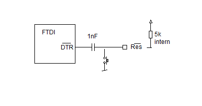
But this requires that you invert the DTR output with the FT-Prog application.
The other possibility is to use the diode, but with RTS instead of DTR. PropTool, and others have an option to use the RTS line for reset. RTS gets normally not affected on COM open and close.
Andy
Thanks for the feedback so far. Keep it coming.
So in review, what's nice about the FLiP reset circuitry is that by using the high-pass (differentiator) circuitry it makes the RESn transition sensitive to the DTR signal but level (or state) agnostic. Which is awesome. Simplifying and replacing that circuitry with a single diode might work under certain strict conditions.
First let's assume that the FT231X is always powered up whenever the Prop is. My design will ensure all circuitry receives 3.3V (from the DC/DC converter) regardless of the input source, which can be USB, external 9V, or both. Doesn't matter. That's a change from the FLiP which appears to only use the 5V USB to power the FT231X.
Now, if the initial power-up state of DTR is LO, diode is forward biased, reset is now held LO, so this won't work.
However, the FT231X can be programmed to invert the outputs, so initial power-up state of DTR is now HI, diode is reverse biased, reset is HI, so this should work. I can then manually toggle DTR to trigger a reset via my PC application.
There's more trouble though if the FT231X automatically activates DTR upon seeing a USB link, and deactivates upon losing the link. The former would work fine if connected to my PC, but the latter won't because I also need stand-alone operation and deactivation of DTR will force the Prop into reset.
Does the FT231X automatically activate/deactivate DTR depending upon USB connect/disconnect status? I don't know.
Using RTS instead as Ariba suggested would work assuming I can get its power-up state to be HI and it stays there regardless of connection status. Hence the only time it will ever change is if manually toggled by my PC application when connected.
Clearly I need to do more research on the status of DTR upon power-up and USB connection/disconnection to the PC.
Now let's look at using the FT231X to provide a 6MHz clock signal to the Prop instead of using a crystal.
Recall that the FT231X will always be powered up whenever the Prop is, so after bootup the question becomes will it always be providing the 6MHz signal regardless of connection status? I don't know.
Another question is how stable is the 6MHz signal, how much jitter does it have, and can the Prop live with all of this, or will it go completely nuts?
Time to dig deep into the various FT231X documents and perform some bench tests if I can...
Also keep in mind the Xtal-less UARTS (which is most these days) use a RC oscillator that is locked to the USB 1ms frame.
That means even after lock, you will see sawtooth corrections to the frequency, which will be in the 0.1~0.6% ballpark.
I've taken the CLKOUT to probe / test pins before, but have never used it for serious clock source use. It's useful to have as a test source to confirm main sysclk settings via a 'second opinion'.
In most cases, upgrade of the xtal to a Osc or TCXO, is a better solution as the Prop has very nice 32b timers. Removing a xtal makes more sense on a 50c MCU....
I use a transistor with inbuilt bias resistors so its a tiny SC70.
There are reasons we invert DTR with the RC-transistor circuit. When switching between programs such as downloading and then running a separate terminal program Windows drops DTR and would cause a prop reset.
I don't have an interface board with an FT231X chip installed, but I do have one with an FT232R so I've been able to conduct some tests. For this discussion LO=0V and HI=3.3V.
A. Observations:
Upon Powerup:
DTR line goes from LO to HI and stays there.
RTS line toggles from LO to HI several times before staying HI. Reason is unknown.
FT232R UART signals can be inverted if needed but in this case wasn't necessary. Signal levels are exactly as needed to properly operate the diode reset circuit.
FT232R CBUS Port Signal Mapping:
CBUS0 -> TXLED
CBUS1 -> RXLED
CBUS2 -> General Purpose I/O
CBUS3 -> General Purpose I/O
CBUS4 -> 6MHz Output Clock
The 6MHz clock signal appears solid on the scope.
B. Summary
FT232R likely can be used to trigger Prop reset via diode circuit and provide a 6MHz clock source
to the Prop to achieve 96MHz operating frequency.
The FT232R must remain powered at all times to achieve the desired functionality.
FT232R can operate in "internal powered" mode instead of USB bus powered.
FT232R internal power must be between 4.0V and 5.25V
The requirement for two power buses (3.3V and 5V) increases design complexity. Circuitry must
take two input sources (either 5V USB bus or 9V external DC) and generate 3.3V and 5V outputs.
Keeping FT232R powered continuously also feeds 3.3V via a 1.5K resistor to the USBDP port
making it "hot"
Keeping USBDP continuously "hot" violates USB specs and could lead to connectivity problems
when connecting to a host.
Connection to USB host would likely only ever occur when programming the Prop.
Prime objective of this Project is to reduce needed components thus decreasing circuit complexity.
Solution to the continuous USBDP "hot" problem must be formulated with minimal circuit complexity.
If this all works out I will likely go with the FT232R instead of the FT231X because I have some plans on using those two spare CBUS I/O ports to perform an additional function...
That assumption will be essential to your success, without adding even more external circuitry. The reason is that if the FTDI chip is not powered, and the Prop is, the Prop will power it parasitically through its TX pin, causing an endless series of resets. (At least that was true of the FT232R.)
BTW, the FLiP does have a 512K EEPROM on board.
-Phil
Absolutely. That's the only way this idea will work. The Prop and the FT232R must always be powered at the same time. It's not only the parasitic power issue you mentioned holding the Prop in perpetual reset. If the FT232R isn't powered, or it is but somehow slipped into SUSPEND mode, it won't output the required 6MHz clock signal so the Prop would be dead in the water even if it wasn't held in reset.
I was hoping that the FT232R would be able to operate at 3.3V using internal power mode since I would have been able to take the input power source(s) of either USB bus, 9VDC, or both, and condition it to only a single 3.3V output to power everything. Unfortunately, the FT232R requires a minimum of 4.0V to operate in this mode, so now I will need my DC/DC converter to provide both 3.3V and 5.0V output.
My biggest concern about continuous power on the FT232R is the fact that it will always keep the USBDP port energized. I will need to run some experiments to see what kind of havoc it will wreak on the USB host port on the PC.
Yes, the FLiP does have a 512 kilobit EEPROM, or 64 kilobytes, but in my case I need 4096 kilobits or 512 kilobytes. Why? Because my C application is currently around 128 kilobytes in size and growing.
My existing add-on board does this by adding a 64 kilobyte, a 128 kilobyte, and a 256 kilobyte EEPROM to get me there. It works but it's a kludge. My new module would just have two 256 kilobyte EEPROMs instead.
Plus I need two 512 kilobyte SPI SRAMs, each operating in Quad Mode, and wired in the "Rampage" configuration yielding an 8-bit databus. Again, my add-on board has this arrangement too and it works well. My opinion is that the "Rampage" configuration is the best arrangement for external RAM using the fewest number of pins. The Catalina C compiler supports this and I found it's execution speed acceptable for my application.
I realize these additions are pushing me into the inherent capability of the Prop2, but as mentioned I'm not ready to make the leap yet (even though I do have a Prop2 development board I got from Parallax).
I think you will find that a capacitor and a SOT363 transistor with internal bias resistors and xtal (I use a 12MHz 3225) will be way smaller than any extra 5V regulator and the cap/diode circuit you are using, plus the issues you haven't discovered when Windows does a DTR transition between programs.
But hey, give it a go.
As usual I would advise for a Jumper between P1 reset and everything else.
So you can decide if USB can reset or can't.
Enjoy!
Mike
Understood, and reduction in circuit complexity is a primary objective here at this preliminary stage.
This imaginary new module will be plugged into a carrier board which will supply it with 5VDC, so if I restrict the new module to this level instead of 9VDC, the circuit complexity will be reduced.
I could use two schottky diodes to isolate the USB 5VDC and the carrier 5VDC from each other, similar to how the FLiP does that now (although the FLiP allows up to 9VDC input).
The 4.7VDC (or thereabouts) emerging from the schottky diodes can then be fed directly into the FT232R satisfying its input power requirements when operating in internal power mode.
The FT232R 3.3VDC output can supply up to 50 mA for external circuits, so I could connect the two 256KB EEPROMs (10 mA total) and the two 512KB SPI SRAMs (20 mA total) to this output.
For the Prop itself I could use a 3.3V LDO regulator like the AP7343Q to drop the 4.7VDC down to 3.3VDC. This LDO regulator can supply up to 300 mA of current, so I could connect the EEPROMs and the SPI SRAMs to it as well. I prefer to use the linear LDO instead of a switching regulator due to size constraints.
The FT232R will supply a 6MHz clock signal to the Prop eliminating the need for the crystal. I'm assuming the Prop can live with this and the jitter and variances won't adversely impact RS232 communication with a GPS receiver and WiFi radio (both operating at 115.2K baud).
Yeah, the flakiness of what Windows will do to the DTR line is a concern. It should respond to the DTR set command issued to it by the programming application I will use to upload new code to the Prop, but Windows is Windows so who knows what it will do.
Now that's a thought. I could also use a couple of solder pads to accomplish the same thing. If USB reset works then create a solder bridge between these two pads. But if it doesn't, then ... back to the drawing board
My thinking is more - jumper on programming/reset enabled - jumper off who cares what windows does with DTR
Mike
Or maybe just a microswitch allowing manual reset only and forget about DTR completely.
The FLiP has this feature but also allows reset via DTR.
The question I need to answer is do I need both like the FLiP, or should I go with the microswitch only...
You won't be able to load a program without using DTR, due to the reset timing requirements.
-Phil
Of course you can load with manual reset, the timing is fairly lax
I sure wouldn't wanna have to, though!")
IMO, that's a simplification too far.
-Phil
The simplest way would be to leave off the USB completely and just buy ONE PropPlug to use for programming. In my not so humble opinion having USB on every P1/2 board is complete Steer Manure,
Mike
For some applications, having in circuit programming of the EEPROM is the kiss of death. Socket the EEPROM and program / reprogram it on a separate board when needed.
Many thanks for the comments, ideas, and suggestions here.
I especially liked the commentary about the FT232 USB chip. It ranged from the necessity of having the DTR to achieve proper reset timing, to being complete steer manure on the prop board
The truth is that for my design the FT232 is a necessity, not only for DTR reset, but also to provide a 6 MHz timing signal to the Prop. The FT232R, which is probably what I will use, also has some spare CBUS signals that I want to assign to a unique task. Having CBUS signals to blink the TX and RX lights is also quite handy, so that feature will be retained.
The idea that the EEPROM should be socketed is also something I'm looking at.
I've been testing bits and pieces of the hardware and have already written code in Windows to access the FT232R using its FTDI API, and the results look pretty good.
My next step is to breadboard the Prop1, FT232R, EEPROM, SPI SRAMs, power conditioning circuitry, various discrete components, etc., to verify proper operation before I commit this design to a PCB...
Hehe, yes you will get a range of opinions on here.
To be fair, it does depend on the final use case. If USB is only used for rare code update download, no-comms-onboard can make sense,
If you want to connect many IO's, and always use USB, then a specific chip is a better solution.
The FT232 is quite old and thus has a high price.
You may want to also qualify similar but newer parts like CP2102N (28 pin version has GPIOs ?) or even the FT232H, which is showing a slightly lower price than FT232R, and it has higher baud and a crystal time base.
Keep in mind any non-xtal USB chip will have poor 6MHz specs (or no signal at all) if the USB frame signal is not present.
Most use a DPLL to lock to the 1ms frame, so you should check the jitter that causes.
I was thinking about older FT232R vs newer FT231x and clock generation etc, and I find some details in the data
FT232R says : 6 MHz ±0.7% Clock output not stellar, but ok for UARTs
FT231X has this new feature : Time Stamp CBUS0, CBUS1, CBUS2, CBUS3 Toggle signal which changes state each time a USB SOF is received
So I used FT_Prog to enable the USB SOF toggle onto CBUS3 and applies the scope and counter...
Here is the scope and notes :
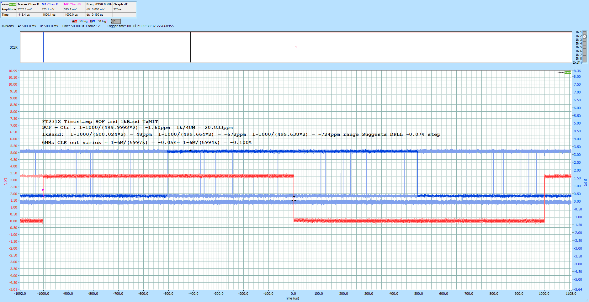
Interesting to see the FT231X Time Stamp toggle appears to have PC-crystal stability, whilst the FT231X 6MHz wanders about with about 0.05% jitter in 100ms gate times.
ie the 6MHz is post DPLL and the USB-SOF seems to have a direct hardware pathway even outside the on chip 48MHz oscillator sampling.
ie it could be practical to use a compact, low cost ceramic resonator on P1, and connect the CBUS SOF as a calibrate point.
CSTNR6M00GH5 is 4520 case and 0.07% for about 20c, or you can get 6MHz Oscillators as small as 2016, tho cheapest Osc are larger, eg C387333 S3D6.000000B20F30T Shenzhen SCTF Elec 6MHz ±20ppm 3.3V 20mA SMD3225-4P 39c/100
My PC here must have a good clock stability, I wonder how that varies across PC's ?")
Apart from using the DTR signal via a diode to control Prop1 reset, there are at least two issues that are bothering me in regards to using one of the FT232R CBUS outputs as a 6MHz clock source for the Prop1:
The FT232R must be powered up at all times, whether the USB port is connected to the PC or operating stand-alone. This means the FT232R must operate as "self powered" instead of "bus powered" and configured to never enter standby mode (which will kill the 6MHz clock). But that also means that USBDP is always "hot" (i.e. energized via a 1.5K ohm resistor connected to the "self powered" supply). This violates USB specs. For stand alone operation I don't see any problem here. But if I connect up to the USB bus on the PC I don't know what type of havoc it will wreak. Will it damage the PC? Will it drive it nuts to the point that the PC won't recognize the attached device? Am I too worried about this?
The Prop1 will be using the Four Port Full Duplex serial driver to communicate with a GPS receiver, a WiFi radio, a monitor port, as well as the console port (pins 30 and 31). Maximum baud rate on all ports will be 115.2Kbps, with the GPS receiver likely operating at 38.4Kbps or 57.6Kbps. Will the jitter from the 6MHz clock signal into the Prop1 adversely affect the serial communication? I don't know. My application won't need any other type of tight, time critical processes. So maybe the serial communication will be fine, or maybe it won't.
I'm still putting together my parts list, so I haven't started the breadboard build yet. I can speculate about the performance all I want, but in reality It will take the actual physical hardware and bench testing to answer these nagging questions.
With those types of issues in the air, maybe it's a good idea to do a plan-A and plan-B type PCB design ?
You could fit an alternative 6MHz choice, so that a board respin is not needed, should you find field issues.
Is size a big issue on the board, or even a few cents in BOM ?
And that's precisely why I want to breadboard everything first -- so I won't have to consider a PCB respin. If it works great on a breadboard then there's a good chance it will work on a PCB.
Size is an issue since I want a footprint comparable to the FLiP. That may be a tall order given that my module will need at least one EEPROM and two SPI SRAM chips, the USB circuitry, power conditioning circuitry, and all of the discrete components.
Looking through a drawer I just found several blank Memory Module PCBs that I designed last year. I damaged the original one so I need to populate a new one with the EEPROMs and SPI SRAMs. The FLiP plugs onto this module and presto I have 512K EEPROM and 512K SRAM. This alternative would be a faster approach to get me to my destination compared to a complete redesign, but the redesign would be cleaner than this kludged FLiP and Memory Module arrangement. On the plus side, it did work until I damaged it.
But today I spent a good amount of time finally working with my Prop2 Eval Board and the FlexProp compiler. I think I'm in love with both")