As I don't have even a single one of those matrix displays, I simply setup an emulation, which is running in a bitmap debug window. The architecture makes sure that in the main code most of the things stays intact, when the real hardware would be available. Only the screen-buffer needs to be written to the real display instead of the debug window.
Today I finished some circle drawing that would correctly wrap around the edges of such a display. Current limitation is are the top and the bottom screen, where the right special treatment is still missing.
Due to the fact that circles have some more levels of symmetry, I think proper handling of boxes will be different.
I know, dividing the screen into 6 pieces (top/bottom/left/right/front/back) instead of 3 pieces (circumference/top/bottom) would make some things easier, but this way the software is more or less independent from the way of how the displays are chained. Who knows .... maybe it will be optimized out later.
As the demo code is not using any hardware, everybody can test it out and see what the debug window shows.
I'm driving this with a 60A 5V power supply so I can do full brightness testing... (each panel max of 8A)
The display is wonky due to it currently being configured for 1 panel. The first panel on the left is showing the correct display, while the remaining panels to the left show the same data just 1 row offset for each further panel.
I need information on how you installed the "pcb_liner". Are these only loose or do they come under the "snap_joint_cap"?
If i look your Photo it seems that your board is covered by a second.
Pls Help
Thanks
The PCB liners snap into place with the dimples aligning to the side holes on the snap joints (and similarly to the magnetic joints).
They should snap in with a satisfying fit, with medium pressure applied around the edges.
To remove, them just put a spatula or something similar under a corner and pry gently.
As I don't have even a single one of those matrix displays, I simply setup an emulation, which is running in a bitmap debug window. The architecture makes sure that in the main code most of the things stays intact, when the real hardware would be available. Only the screen-buffer needs to be written to the real display instead of the debug window.
Today I finished some circle drawing that would correctly wrap around the edges of such a display. Current limitation is are the top and the bottom screen, where the right special treatment is still missing.
Due to the fact that circles have some more levels of symmetry, I think proper handling of boxes will be different.
I know, dividing the screen into 6 pieces (top/bottom/left/right/front/back) instead of 3 pieces (circumference/top/bottom) would make some things easier, but this way the software is more or less independent from the way of how the displays are chained. Who knows .... maybe it will be optimized out later.
As the demo code is not using any hardware, everybody can test it out and see what the debug window shows.
MagIO2, This is awesome work. I was thinking about how to line up different projections for the cube surface, but this seems to be a step in the right direction.
Regarding the order of the panels in the current design, there is a basic concept here: https://github.com/jshook/p2_p2_cube/blob/master/3d_models/assembly.md
If we need to modify the daisy-chaining to fit the graphics driver we can find a way, but it may require some fancy wiring. The layout above is relatively straightforward from a wiring and assembly perspective.
Regarding mapping the example buffer to the cube, I think it is a great way to get started lighting up pixels.
Here is a stretch goal for us to think about: If a user wants to draw basic graphics (standard primitives) using a polar coordinate system which automatically locks to the magnetic north and up (using a 10-dof IMU), can we make that easy? (I know that is not easy for us!, but can we make it easy for the experimenter by doing the hard part of this mapping?) This brings some interesting mapping problems up, that have all been solved before in other places, but not yet for the P2P2 cube. It would require us to provide some library/driver code for projecting, segmenting, filling, and so on using that coordinate system.
I need information on how you installed the "pcb_liner". Are these only loose or do they come under the "snap_joint_cap"?
If i look your Photo it seems that your board is covered by a second.
Pls Help
Thanks
The PCB liners snap into place with the dimples aligning to the side holes on the snap joints (and similarly to the magnetic joints).
They should snap in with a satisfying fit, with medium pressure applied around the edges.
To remove, them just put a spatula or something similar under a corner and pry gently.
@AndreasS
I realize now that you were talking about an earlier picture where I showed an additional interior box. After building a few prototypes of a third "inner core" structure, it became clear that it was probably too much trouble and not much benefit. So I decided to just use the 2 layers and leave the interior design as an open question. With the liner plates, it seems that some spacer blocks and foam parts are likely better than the additional scaffolding anyway.
We might eventually want to add an interior "drop-in" rack for parts, but with the current layout based on the proto boards, it's premature to lock something in.
I just got my first P2 panel and I see that the back is held on with 4 1 millimeter screws. That's not going to hold up being turned around with parts inside.
Also the face has the LED's exposed and your fingers are rubbing on them leaving all kinds of junk. I think it's going to need a diffuser over them to protect the LED's and allow better handling of the cube.
I'm driving this with a 60A 5V power supply so I can do full brightness testing... (each panel max of 8A)
The display is wonky due to it currently being configured for 1 panel. The first panel on the left is showing the correct display, while the remaining panels to the left show the same data just 1 row offset for each further panel.
Hello,
nice to see.
Please help me a little.
I'am new P2 Boards.
Which Software Propeller Tool?
With this driver code? https://github.com/ironsheep/p2-HUB75-LED-Matrix-Driver
Can i take brightness lower so that i can test with weaker power supply?
@iseries said:
I just got my first P2 panel and I see that the back is held on with 4 1 millimeter screws. That's not going to hold up being turned around with parts inside.
Also the face has the LED's exposed and your fingers are rubbing on them leaving all kinds of junk. I think it's going to need a diffuser over them to protect the LED's and allow better handling of the cube.
Mike
The panels I have, which should be the same as you have now, have 12 screws -- 2 in each corner and one along each edge. The build plans specifically call out replacement screws for this which will have the right level of depth with the new printed frame.
Moving these panels over to the 3d printed frames is probably the most skill-intensive step of the whole cube assembly. Given the size of the screws and the depth of the FR4, it takes a delicate touch on screw tension. I honestly think we should use a light-gauge torque wrench and come up with a torque setting that is considered reliable.
Regarding a diffuser, I do agree that something should be provided. If we can find a suitable material that is thin enough, I'll make a version of the face plates which have bigger edges and a groove on two opposite sized to hold it. maybe something like a shelf liner or CFL light cover from [insert your local hardware store name here].
I'll swing by the local hardware store and see if I can find something suitable for this tonight.
@"Stephen Moraco"
Do you have any specific pointers on the brightness scaling? We had discussed this before but I wasn't sure if it has been implemented yet or not.
@AndreasS That is the driver we plan on using. Stephen has been working with this project as a driver/hardware provider as well.
@AndreasS said:
@"Stephen Moraco" said: News
The now shipping Parallax Matrix Panels work with the current driver!
I'm driving this with a 60A 5V power supply so I can do full brightness testing... (each panel max of 8A)
The display is wonky due to it currently being configured for 1 panel. The first panel on the left is showing the correct display, while the remaining panels to the left show the same data just 1 row offset for each further panel.
Hello,
nice to see.
Please help me a little.
I'am new P2 Boards.
Which Software Propeller Tool?
With this driver code? https://github.com/ironsheep/p2-HUB75-LED-Matrix-Driver
Can i take brightness lower so that i can test with weaker power supply?
@Twyyx said:
Do you have any specific pointers on the brightness scaling? We had discussed this before but I wasn't sure if it has been implemented yet or not.
In the file isp_hub75_color.spin2 you'll find two methods: setBrightness() and getBrightness(). This mechanism is doing nothing in the current release but it will be functional when I complete my multi-panel fixes and release driver support for the P2 P2 Cube. When we build the cube code, we need to simply call this method once during driver set up.
The brightness is used to scale the [0-255] color intensity value to a [0-(maxLimit-1)] value. The default value for brightness amounts to no scaling.
Also, since I've been working with the driver I now know that the driver-natural panel indexing for your wiring is as follows: hub75 card -> bottom[5] -> side1[4] -> side2[3] -> side3[2] -> side4[1] -> top[0]
In panel chains for this driver, the 0'th panel is the one at the opposite end of the chain from the driver card.
GAH! As I'm writing this I probably need to add display orientation configuration values so one can create a flat multi-panel display place it on a wall in some orientation and then, with these new configuration values, we can tell the driver which panel is really in the top-left corner of the display... sigh... always more adding to the TODO list as I try to clear things from the list. ;-)
While I am adding methods so one can do specific things to an individual 64x64 panel, it is also likely that we want whole cube methods for drawing/placing images/text as well as 360-degree-video frame mapping to the entire cube, etc. Also, with our IMU we'll probably want the IMU to possibly adjust the frame of reference for the drawing routines so that, say, the bottom image stays on the bottom of the cube as the cube is rotated... this could also mean that bottom could be defined as the bottom-most part of a three-panel corner of the cube which is facing down... depending upon how far we want to go with this. ;-)
Hello,
today I only wanted to test it with one panel because I only have a 10A & 20A 5V power supply.
As already mentioned, the P2 board is new to me and I need support.
I successfully tested Hello Blinky.spin2 first.
But after I connect the P2-Eval Hub75 adapter board, the red lamp on the USB / PC connection lights up.
Then I tried to connect another 2A power supply to the second AUX / USB. The data cable is connected to the Hub75 adapter board and a 10A 5V power supply unit on the LED panel.
What am I doing wrong? Do I have to move a jumper? And can you please give me an example with which I can test this one display via Propeller Tool?
The specs for the 64x64 panel says they are using 2121 LEDs.
These LEDs use Red: 20 milliamps, Green: 10 milliamps, and Blue: 5 milliamps, or a total of 35 milliamps.
So the panel with all the LED's lite would require 143 amps = 4096 * 35 milliamps.
Well, this is not correct as you can only turn on a single row at a time. The real power would be 2.24 amps = 64 * 35 milliamps.
So to drive 6 panels you would need 13.44 amps = 6 * 2.24.
Now the panel spec says it needs 25 watts or 25 / 5 volts = 5 amps.
So the electronics on the board itself need 2.5 amps just to run the panel?
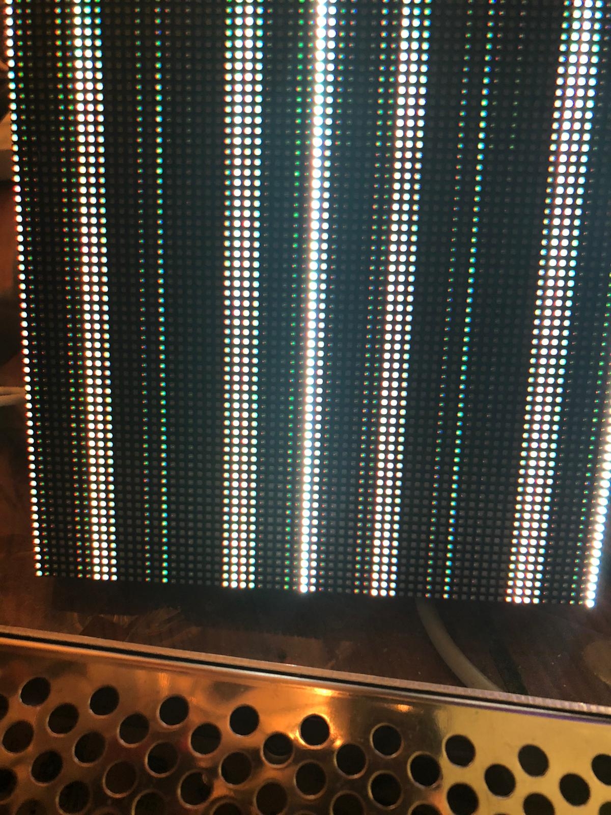
I just tested, when I load "serial_to_logicdisplay.spin2" (from examples) I get at least a couple of rows of glowing LEDs (see picture)
Can someone explain to me how I can start as a beginner? Drivers, libraries, etc. I don't understand why the examples from Stephen and MagIO2 don't light up my panel.
You at least should understand that not all spin2-files contain code which can be run. You need to pick a file which usually contains a first function called main(). These are the programs that make use of all the rest of the objects.
The code I posted does not contain any hardware driver because I don't have those panels. It was only an experiment to see in a debug window, how primitive drawing functions could be wrapped around the edges in a cube setup. ( Well to be honest, it would allow any kind of setup and not only cubes, because there is a data-structure, which tells the drawing function where the panels sit in relation to other panels. )
On the other hand it would not be too hard to replace the debug window driver with a real one and make the code run on a physical setup. Would probably only include some copy and paste and tweaking from the existing driver.
But again ... I don't have a panel yet, so no reason to hurry from my side.
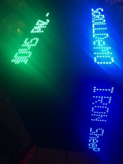
Now I have something going on on the display with "isp_hub75_demoText.spin2". (see picture)
Iron Sheep demos are made for 64x32 panels. How can I adapt this for 64x64?
I also noticed that I have 2 different types of panels, 6 x ICN2038 and 6 x ICN2037.
@""Stephen Moraco"
please help me how can i use the demos 64x64? at the moment my upper rows are black / off
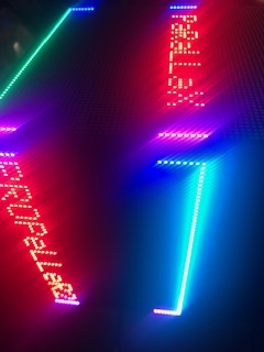
Ok i got something new but not total ok :-)
It goes forward, but i need some sunglasses It's so bright
but at the moment the upper rows are black / off for me
I connected one other panel (icn2038) in this postion and it has wrong colors but the text lines don't cross.
So i looked at the panel with errors and here is what i have found that one part is missing from china
The specs for the 64x64 panel says they are using 2121 LEDs.
These LEDs use Red: 20 milliamps, Green: 10 milliamps, and Blue: 5 milliamps, or a total of 35 milliamps.
So the panel with all the LED's lite would require 143 amps = 4096 * 35 milliamps.
Well, this is not correct as you can only turn on a single row at a time. The real power would be 2.24 amps = 64 * 35 milliamps.
So to drive 6 panels you would need 13.44 amps = 6 * 2.24.
Now the panel spec says it needs 25 watts or 25 / 5 volts = 5 amps.
So the electronics on the board itself need 2.5 amps just to run the panel?
Mike
Mike, I don't know how much of this you already know, but I'm sharing my reaction to it in case it is helpful.
The current required will be more a function of the the power management of the constant current drivers in the LED driver ICs. In other words, even if you could drive the LED at full current on all elements, the driver IC may not do so. You would typically drive the elements at lower than their maximum rated current if you want to improve longevity. So, there is probably some headroom built into the spec.
Further, the 25W spec sheet number is probably a safe margin to make sure people are not building inadequate power systems for these. You typically want your available power to be higher than any instantaneous load. Thus, if you are specifying a "safe" power requirement, you're going to have to build in a margin. We don't actually know what the really scientific power requirements are with certain assumptions like transient loads and ripple sensitivity.. And the builder of these panels probably doesn't either. It's just more practical to request a high enough power requirement that you can be fairly sure it's not going to be too low by some safe margin.
For us, that means we might be able to turn it down and experiment, but brown-outs are also not safe for some panel designs, so beware of trying to power things at the limit of a power supply. Usually as you approach using the total power available, the ripple increases dramatically unless you are designing a PSU for low-noise.
In my case I have some 50C 4.6AmpHour LiPo batteries at 7.4V. I don't know at which voltage the voltage regulators will stop converting yet.
@AndreasS said:
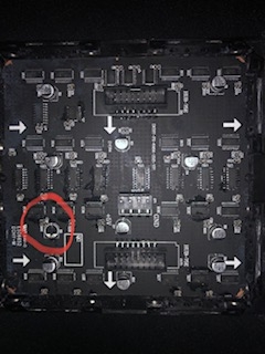
I connected one other panel (icn2038) in this postion and it has wrong colors but the text lines don't cross.
So i looked at the panel with errors and here is what i have found that one part is missing from china
That looks repairable. The PCB liners are matched to these electrolytic capacitors and should shield them very well.
Even if you have to solder a couple "pig tails" to that surface, you can hang a cap off of it. This is probably just a load smoothing cap of some kind to make sure the driver ICs have saturating current.
@AndreasS said:
I connected one other panel (icn2038) in this postion and it has wrong colors but the text lines don't cross.
So i looked at the panel with errors and here is what i have found that one part is missing from china
That looks repairable. The PCB liners are matched to these electrolytic capacitors and should shield them very well.
Even if you have to solder a couple "pig tails" to that surface, you can hang a cap off of it. This is probably just a load smoothing cap of some kind to make sure the driver ICs have saturating current.
It's pretty fun to see your progress.
Actually,
This board layout looks slightly different than mine
Can you take a higher resolution photo for me so I can get an idea about what needs to be done for the liners? I thought these panels were one and the same as I had already ordered. Is this a different model than Parallax sells?
I was watch a video and stephen was driving 6 panels with a 60amp supply and said each panel was rated at 8amps. This sounded awful high and would make using the panel with a battery impractical.
I did some measurements of my panel and found that with all the LED's on it was under 1 amp. Far better than expected. I then slowed the refresh rate way down to about a tenth of a second per refresh where the panel started to flicker and was able to get the current up to 2 amps. Still well short of 8 amps.
Also my calculations was wrong in that I only counted one row when actually two rows are turned on at the same time. So .035 amps x 128 = 4.48 amps.
All 6 panel lights, but the lines cross at the last panel. (picture) Thi is the last panel of 6 (ICN2037).
Pls can you help me got 6 panels running?
I am working on certifying the driver for 6 panels. To date I have 4 of the 6 panels running well but when I configure for 5 or 6 the display is not correct. I'm chasing this. You are ahead of me.
Re the .bmp code is an example and needs a bit of understanding moving it from 64x32 to another panel or panelSet geometry. If you study the code it shouldn't be too hard. Just don't expect it to work without modification.
My 8A per panel rating is measured from my cheap bench supply running the panel full out (all led's full-on) at ~380 fps (16 PWM frames per frame of the ~380, data clock at 15.4 MHz). I'm working to prove what we can do at the limits so I run much faster than we would need in the cube application. At my speeds, the full cube would max out at ~63 fps (380 fps/6 panels)
Another thought... re power. Even at my speeds the examples I have run at 3 amps or lower (most use less than 1A.) PWM really reduces the power need at normal brightnesses and color mixes. We should have a range of signalling speeds available to us once we apply brightness limits which will limit our max power draw.
Also a note: if you configure for 1 or 2 panels all of the remaining panels display should be timing-correct, no flicker jitter, color shift, etc. The 3&4 should be shifted down by a small number of rows and 5&6 likewise but more rows. If you configure for 1 panel then each panel further from the hub75 card (from the driven end of the cable) will drop by 1 more row than the last. Ignoring this shift you will have a good checkout of your hardware as all panels should be rock solid with respect to what's being displayed. This is a great initial hardware checkout.
@"Stephen Moraco"
Can you please help me? How you get 6 Penels to work with same picture on everyone?
What is wrong with my setting? Or is it because of my diffrent panels?
If i try higher than 64 x 64 i get an memory error.
(sorry for my bad english)
@AndreasS said:
Can you please help me? How you get 6 Penels to work with same picture on everyone?
What is wrong with my setting? Or is it because of my diffrent panels?
If i try higher than 64 x 64 i get an memory error.
(sorry for my bad english)
If you set to 4 and 4 with my latest driver version that's the best you'll be able to do until I figure out what's happening...
But as I indicated... 4 is the max that works correctly with my current code. I'll try to get it pushed to the repo (not released) so that you can pull the latest to get 4 panels working.
I don't have a second panel but thought I would investigate how the follow on panel would work with the cable.
So what it looks like is that instead of clocking out 64 colors you would clock out 128 colors where the first colors show up on the second panel. Another words the panel that gets plugged in is now the first panel and not the second.
So I monitored the color values on the cable with my scope and see that the color changes on the rising edge of the clock pulse. This is fine except that the color value changes on the 64th pulse and not the 65th. This would mean that the last pixel on the first display would be the wrong color.
Am I looking at this correctly? 64 clocks = 64 LED's.
@AndreasS said:
@"Stephen Moraco"
Can you please help me? How you get 6 Panels to work with same picture on everyone?
Andreas, I repaired the driver so that a configuration like:
PANEL_DRIVER_CHIP = CHIP_ICN2037
' (2) describe the panel electrical layout
MAX_PANEL_COLUMNS = 64
MAX_PANEL_ROWS = 64
PANEL_ADDR_LINES = ADDR_ABCDE
' (3) describe the organization of panel(s)
' panels organization: visual layout
' [6] ' one row of 6 panels (our cube is electrically 1 row)
'
' (4) describe the organization in numbers of panels
MAX_PANELS_PER_ROW = 6
MAX_PANELS_PER_COLUMN = 1
...will now work. I've more testing to do against other panel types to make sure I didn't break anything and I'm working on more demo code for multipanel demos. After this testing, I'll be officially releasing a new version. I thought you might want to get the latest from my repository so you could see your hardware working now instead of waiting for my release.
Also, from here on.... the MAX_PANELS constant is no longer specified by the user in this configuration file. It is just calculated within the driver as:


Comments
Hello Twyyx,
I need information on how you installed the "pcb_liner". Are these only loose or do they come under the "snap_joint_cap"?
If i look your Photo it seems that your board is covered by a second.
Pls Help
Thanks
Maybe it makes sense to move some stuff to this thread ...
In the following thread I did some experiments with my GraphicsDriverArchitecture, to see if it would be useful for a P2P2 Cube setup:
https://forums.parallax.com/discussion/173278/display-driver-architecture
As I don't have even a single one of those matrix displays, I simply setup an emulation, which is running in a bitmap debug window. The architecture makes sure that in the main code most of the things stays intact, when the real hardware would be available. Only the screen-buffer needs to be written to the real display instead of the debug window.
Today I finished some circle drawing that would correctly wrap around the edges of such a display. Current limitation is are the top and the bottom screen, where the right special treatment is still missing.
Due to the fact that circles have some more levels of symmetry, I think proper handling of boxes will be different.
I know, dividing the screen into 6 pieces (top/bottom/left/right/front/back) instead of 3 pieces (circumference/top/bottom) would make some things easier, but this way the software is more or less independent from the way of how the displays are chained. Who knows .... maybe it will be optimized out later.
As the demo code is not using any hardware, everybody can test it out and see what the debug window shows.
News
The now shipping Parallax Matrix Panels work with the current driver!
I've setup my hardware to begin the finishing of the driver to support our full Cube of panels (6 64x64 panels). My Test setup is shown on my hardware turnon page: https://github.com/ironsheep/p2-HUB75-LED-Matrix-Driver/blob/main/HardwareTurnon.md#p2-cube-driver-checkout
I'm driving this with a 60A 5V power supply so I can do full brightness testing... (each panel max of 8A)
The display is wonky due to it currently being configured for 1 panel. The first panel on the left is showing the correct display, while the remaining panels to the left show the same data just 1 row offset for each further panel.
The PCB liners snap into place with the dimples aligning to the side holes on the snap joints (and similarly to the magnetic joints).
They should snap in with a satisfying fit, with medium pressure applied around the edges.
To remove, them just put a spatula or something similar under a corner and pry gently.
MagIO2, This is awesome work. I was thinking about how to line up different projections for the cube surface, but this seems to be a step in the right direction.
Regarding the order of the panels in the current design, there is a basic concept here: https://github.com/jshook/p2_p2_cube/blob/master/3d_models/assembly.md
If we need to modify the daisy-chaining to fit the graphics driver we can find a way, but it may require some fancy wiring. The layout above is relatively straightforward from a wiring and assembly perspective.
Regarding mapping the example buffer to the cube, I think it is a great way to get started lighting up pixels.
Here is a stretch goal for us to think about: If a user wants to draw basic graphics (standard primitives) using a polar coordinate system which automatically locks to the magnetic north and up (using a 10-dof IMU), can we make that easy? (I know that is not easy for us!, but can we make it easy for the experimenter by doing the hard part of this mapping?) This brings some interesting mapping problems up, that have all been solved before in other places, but not yet for the P2P2 cube. It would require us to provide some library/driver code for projecting, segmenting, filling, and so on using that coordinate system.
Can't believe I missed this image! Nice work!
@AndreasS
I realize now that you were talking about an earlier picture where I showed an additional interior box. After building a few prototypes of a third "inner core" structure, it became clear that it was probably too much trouble and not much benefit. So I decided to just use the 2 layers and leave the interior design as an open question. With the liner plates, it seems that some spacer blocks and foam parts are likely better than the additional scaffolding anyway.
We might eventually want to add an interior "drop-in" rack for parts, but with the current layout based on the proto boards, it's premature to lock something in.
I just got my first P2 panel and I see that the back is held on with 4 1 millimeter screws. That's not going to hold up being turned around with parts inside.
Also the face has the LED's exposed and your fingers are rubbing on them leaving all kinds of junk. I think it's going to need a diffuser over them to protect the LED's and allow better handling of the cube.
Mike
Hello,
nice to see.
Please help me a little.
I'am new P2 Boards.
Which Software Propeller Tool?
With this driver code? https://github.com/ironsheep/p2-HUB75-LED-Matrix-Driver
Can i take brightness lower so that i can test with weaker power supply?
Thanks
Andi
The panels I have, which should be the same as you have now, have 12 screws -- 2 in each corner and one along each edge. The build plans specifically call out replacement screws for this which will have the right level of depth with the new printed frame.
Moving these panels over to the 3d printed frames is probably the most skill-intensive step of the whole cube assembly. Given the size of the screws and the depth of the FR4, it takes a delicate touch on screw tension. I honestly think we should use a light-gauge torque wrench and come up with a torque setting that is considered reliable.
Regarding a diffuser, I do agree that something should be provided. If we can find a suitable material that is thin enough, I'll make a version of the face plates which have bigger edges and a groove on two opposite sized to hold it. maybe something like a shelf liner or CFL light cover from [insert your local hardware store name here].
I'll swing by the local hardware store and see if I can find something suitable for this tonight.
@"Stephen Moraco"
Do you have any specific pointers on the brightness scaling? We had discussed this before but I wasn't sure if it has been implemented yet or not.
@AndreasS That is the driver we plan on using. Stephen has been working with this project as a driver/hardware provider as well.
In the file
isp_hub75_color.spin2you'll find two methods:setBrightness()andgetBrightness(). This mechanism is doing nothing in the current release but it will be functional when I complete my multi-panel fixes and release driver support for the P2 P2 Cube. When we build the cube code, we need to simply call this method once during driver set up.The brightness is used to scale the [0-255] color intensity value to a [0-(maxLimit-1)] value. The default value for brightness amounts to no scaling.
Also, since I've been working with the driver I now know that the driver-natural panel indexing for your wiring is as follows:
hub75 card -> bottom[5] -> side1[4] -> side2[3] -> side3[2] -> side4[1] -> top[0]In panel chains for this driver, the 0'th panel is the one at the opposite end of the chain from the driver card.
GAH! As I'm writing this I probably need to add display orientation configuration values so one can create a flat multi-panel display place it on a wall in some orientation and then, with these new configuration values, we can tell the driver which panel is really in the top-left corner of the display... sigh... always more adding to the TODO list as I try to clear things from the list. ;-)
While I am adding methods so one can do specific things to an individual 64x64 panel, it is also likely that we want whole cube methods for drawing/placing images/text as well as 360-degree-video frame mapping to the entire cube, etc. Also, with our IMU we'll probably want the IMU to possibly adjust the frame of reference for the drawing routines so that, say, the bottom image stays on the bottom of the cube as the cube is rotated... this could also mean that bottom could be defined as the bottom-most part of a three-panel corner of the cube which is facing down... depending upon how far we want to go with this. ;-)
Hello,
today I only wanted to test it with one panel because I only have a 10A & 20A 5V power supply.
As already mentioned, the P2 board is new to me and I need support.
I successfully tested Hello Blinky.spin2 first.
But after I connect the P2-Eval Hub75 adapter board, the red lamp on the USB / PC connection lights up.
Then I tried to connect another 2A power supply to the second AUX / USB. The data cable is connected to the Hub75 adapter board and a 10A 5V power supply unit on the LED panel.
What am I doing wrong? Do I have to move a jumper? And can you please give me an example with which I can test this one display via Propeller Tool?
Many Thanks
greetings
Andi
Question about power?
The specs for the 64x64 panel says they are using 2121 LEDs.
These LEDs use Red: 20 milliamps, Green: 10 milliamps, and Blue: 5 milliamps, or a total of 35 milliamps.
So the panel with all the LED's lite would require 143 amps = 4096 * 35 milliamps.
Well, this is not correct as you can only turn on a single row at a time. The real power would be 2.24 amps = 64 * 35 milliamps.
So to drive 6 panels you would need 13.44 amps = 6 * 2.24.
Now the panel spec says it needs 25 watts or 25 / 5 volts = 5 amps.
So the electronics on the board itself need 2.5 amps just to run the panel?
Mike
I just tested, when I load "serial_to_logicdisplay.spin2" (from examples) I get at least a couple of rows of glowing LEDs (see picture)
Can someone explain to me how I can start as a beginner? Drivers, libraries, etc. I don't understand why the examples from Stephen and MagIO2 don't light up my panel.
thanks
Go to the github page https://github.com/ironsheep/p2-HUB75-LED-Matrix-Driver, go into driver folder, pick any spin2-program that has "demo" in it's name and run that.
You at least should understand that not all spin2-files contain code which can be run. You need to pick a file which usually contains a first function called main(). These are the programs that make use of all the rest of the objects.
The code I posted does not contain any hardware driver because I don't have those panels. It was only an experiment to see in a debug window, how primitive drawing functions could be wrapped around the edges in a cube setup. ( Well to be honest, it would allow any kind of setup and not only cubes, because there is a data-structure, which tells the drawing function where the panels sit in relation to other panels. )
On the other hand it would not be too hard to replace the debug window driver with a real one and make the code run on a physical setup. Would probably only include some copy and paste and tweaking from the existing driver.
But again ... I don't have a panel yet, so no reason to hurry from my side.
Now I have something going on on the display with "isp_hub75_demoText.spin2". (see picture)
Iron Sheep demos are made for 64x32 panels. How can I adapt this for 64x64?
I also noticed that I have 2 different types of panels, 6 x ICN2038 and 6 x ICN2037.
@""Stephen Moraco"
please help me how can i use the demos 64x64? at the moment my upper rows are black / off
Ok i got something new but not total ok :-)
It goes forward, but i need some sunglasses") It's so bright
It's so bright
but at the moment the upper rows are black / off for me
Now it works super with scrolling Text on every line with two Panels
@""Stephen Moraco"
many thanks for the testing driver
now i will try why no bmp files working for me.
I have change yours from 64x32 to 64x64 pixels, but dont work.
If this later work i will add more pannels
greetings
Andi
@""Stephen Moraco"
All 6 panel lights, but the lines cross at the last panel. (picture)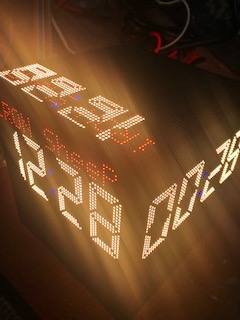 Thi is the last panel of 6 (ICN2037).
Pls can you help me got 6 panels running?
And I couldn't open pictures (bmp) only get black panel.
I connected one other panel (icn2038) in this postion and it has wrong colors but the text lines don't cross.
So i looked at the panel with errors and here is what i have found that one part is missing from china
Mike, I don't know how much of this you already know, but I'm sharing my reaction to it in case it is helpful.
The current required will be more a function of the the power management of the constant current drivers in the LED driver ICs. In other words, even if you could drive the LED at full current on all elements, the driver IC may not do so. You would typically drive the elements at lower than their maximum rated current if you want to improve longevity. So, there is probably some headroom built into the spec.
Further, the 25W spec sheet number is probably a safe margin to make sure people are not building inadequate power systems for these. You typically want your available power to be higher than any instantaneous load. Thus, if you are specifying a "safe" power requirement, you're going to have to build in a margin. We don't actually know what the really scientific power requirements are with certain assumptions like transient loads and ripple sensitivity.. And the builder of these panels probably doesn't either. It's just more practical to request a high enough power requirement that you can be fairly sure it's not going to be too low by some safe margin.
For us, that means we might be able to turn it down and experiment, but brown-outs are also not safe for some panel designs, so beware of trying to power things at the limit of a power supply. Usually as you approach using the total power available, the ripple increases dramatically unless you are designing a PSU for low-noise.
In my case I have some 50C 4.6AmpHour LiPo batteries at 7.4V. I don't know at which voltage the voltage regulators will stop converting yet.
That looks repairable. The PCB liners are matched to these electrolytic capacitors and should shield them very well.
Even if you have to solder a couple "pig tails" to that surface, you can hang a cap off of it. This is probably just a load smoothing cap of some kind to make sure the driver ICs have saturating current.
It's pretty fun to see your progress.
Actually,
This board layout looks slightly different than mine
Can you take a higher resolution photo for me so I can get an idea about what needs to be done for the liners? I thought these panels were one and the same as I had already ordered. Is this a different model than Parallax sells?
Good morning Twyyx,
@Twyyx ,
I was watch a video and stephen was driving 6 panels with a 60amp supply and said each panel was rated at 8amps. This sounded awful high and would make using the panel with a battery impractical.
I did some measurements of my panel and found that with all the LED's on it was under 1 amp. Far better than expected. I then slowed the refresh rate way down to about a tenth of a second per refresh where the panel started to flicker and was able to get the current up to 2 amps. Still well short of 8 amps.
Also my calculations was wrong in that I only counted one row when actually two rows are turned on at the same time. So .035 amps x 128 = 4.48 amps.
Mike
I am working on certifying the driver for 6 panels. To date I have 4 of the 6 panels running well but when I configure for 5 or 6 the display is not correct. I'm chasing this. You are ahead of me.
Re the .bmp code is an example and needs a bit of understanding moving it from 64x32 to another panel or panelSet geometry. If you study the code it shouldn't be too hard. Just don't expect it to work without modification.
My 8A per panel rating is measured from my cheap bench supply running the panel full out (all led's full-on) at ~380 fps (16 PWM frames per frame of the ~380, data clock at 15.4 MHz). I'm working to prove what we can do at the limits so I run much faster than we would need in the cube application. At my speeds, the full cube would max out at ~63 fps (380 fps/6 panels)
Another thought... re power. Even at my speeds the examples I have run at 3 amps or lower (most use less than 1A.) PWM really reduces the power need at normal brightnesses and color mixes. We should have a range of signalling speeds available to us once we apply brightness limits which will limit our max power draw.
Also a note: if you configure for 1 or 2 panels all of the remaining panels display should be timing-correct, no flicker jitter, color shift, etc. The 3&4 should be shifted down by a small number of rows and 5&6 likewise but more rows. If you configure for 1 panel then each panel further from the hub75 card (from the driven end of the cable) will drop by 1 more row than the last. Ignoring this shift you will have a good checkout of your hardware as all panels should be rock solid with respect to what's being displayed. This is a great initial hardware checkout.
Hello,
@"Stephen Moraco"")
Can you please help me? How you get 6 Penels to work with same picture on everyone?
What is wrong with my setting? Or is it because of my diffrent panels?
If i try higher than 64 x 64 i get an memory error.
(sorry for my bad english)
ADAPTER_BASE_PIN = PINS_P32_P47
PANEL_DRIVER_CHIP = CHIP_ICN2037
MAX_PANEL_COLUMNS = 64 'works!!!! for PWM
MAX_PANEL_ROWS = 64
PANEL_ADDR_LINES = ADDR_ABCDE
MAX_PANELS = 2
MAX_PANELS_PER_ROW = 2
MAX_PANELS_PER_COLUMN = 1
thanks
we wrote at the same time :-)
Best Regards
Andreas
This will be the correct values:
If you set to 4 and 4 with my latest driver version that's the best you'll be able to do until I figure out what's happening...
But as I indicated... 4 is the max that works correctly with my current code. I'll try to get it pushed to the repo (not released) so that you can pull the latest to get 4 panels working.
More soon.
Are the Panel64's defective?
I don't have a second panel but thought I would investigate how the follow on panel would work with the cable.
So what it looks like is that instead of clocking out 64 colors you would clock out 128 colors where the first colors show up on the second panel. Another words the panel that gets plugged in is now the first panel and not the second.
So I monitored the color values on the cable with my scope and see that the color changes on the rising edge of the clock pulse. This is fine except that the color value changes on the 64th pulse and not the 65th. This would mean that the last pixel on the first display would be the wrong color.
Am I looking at this correctly? 64 clocks = 64 LED's.
Mike
Andreas, I repaired the driver so that a configuration like:
    PANEL_DRIVER_CHIP = CHIP_ICN2037

    ' (2) describe the panel electrical layout
    MAX_PANEL_COLUMNS = 64
    MAX_PANEL_ROWS = 64
    PANEL_ADDR_LINES = ADDR_ABCDE

    ' (3) describe the organization of panel(s)
    ' panels organization: visual layout
    '   [6]     ' one row of 6 panels (our cube is electrically 1 row)
    '
    ' (4) describe the organization in numbers of panels
    MAX_PANELS_PER_ROW = 6
    MAX_PANELS_PER_COLUMN = 1
...will now work. I've more testing to do against other panel types to make sure I didn't break anything and I'm working on more demo code for multipanel demos. After this testing, I'll be officially releasing a new version. I thought you might want to get the latest from my repository so you could see your hardware working now instead of waiting for my release.
Also, from here on.... the
MAX_PANELSconstant is no longer specified by the user in this configuration file. It is just calculated within the driver as:MAX_PANELS = MAX_PANELS_PER_ROW * MAX_PANELS_PER_COLUMN