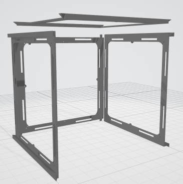
The timespan of the timelapse video is under 2 hours. It was about 1 hour of figuring out how to arrange the build, and an hour actually doing it give or take.
The through-hole post and glue method will drastically speed it up for the next time.
> I dropped a stock LED panel on the concrete floor while rearranging the workspace. This is now the official test panel. It's a good thing I anticipated my own clumsiness on this and bought 2 extras.
You are a wise man I did the same and needed that spare. The good news is it looks like the panels still work even if a few LEDs break off on the edges
The video looks awesome, so exciting to see it come together so quickly like that! Cant wait to see a final version!
BTW I have linked to this forum post from a pinned comment on my Video, once you have a final version ill link to it from the video description proper tho the views on the video have drastically slowed down so I dont know how many people will see it.
Also as I mentioned in my pinned comment, someone has taken my LED Cube Youtube vid, watermarked it, made up a bunch of fake screenshots then is trying to sell a fake cube with it I wont link it here because I dont want to give them any traffic but PM or email me and ill give you the link.
it is basically good to mention @RossH once in a while, being that far out in the nowhere, having to drive for a internet connection ...
We do have an internet connection - but it is a slow and unreliable satellite service. We can mostly do basic browsing and email (although it requires you to have a bit of patience), but we cannot do video.
On the plus side, we often get positive reviews from guests who are trying to wean their kids off the internet!
An early weekend update on the P2 P2 Cube project:
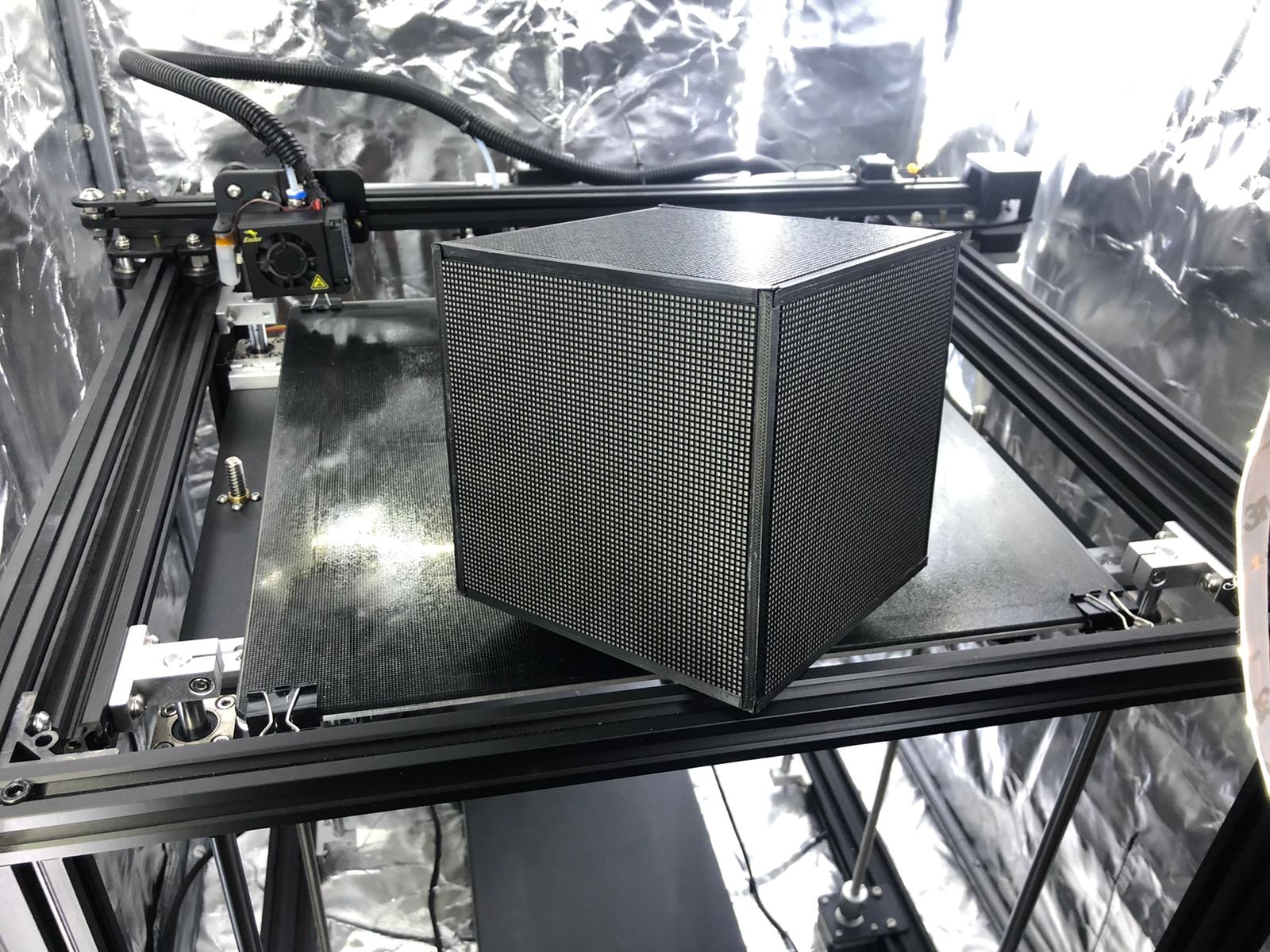
I have done the second full frame build, this time with actual panels. This build incorporated refinements to the 3d models which made building much easier, although it takes a little longer with the joints. It's still just a couple hours. I learned some techniques that need to be folded into the build guide.
Once assembled with the magnetic top, I lost track of which was the top! I realized it needed to be marked with a couple pips on the plastic liner. Problem solved! It's nice that the fit is so close and consistent that you cant tell which side is the magnetic one.
I've been eager to get to this point. The interior design can be finished now. It's clear that the cables will all fit, and -- with a custom subframe that can snap into the interior edge holes, we can maximize the available space inside. This may even allow for some cuboid voids which are perfect places to slot the plastic packed lipo batteries into.
We're almost to the next challenge: Wiring things up and starting on the controller design/layout/programming. Once the interior subframe has been designed around the components I have on hand (P2/edge adapter/battery/PSU), I'll share all the files here and then we can start working on the electronics.
Awesome nice work @Twyyx! Its funny you say you lost track of the top, I had exactly the same issue. My solution was to use a little bit of bluetac and put a bit on the top side, its definately not very elegant tho.
Looking forward to seeing what your plans are for the programming side of things.
Just pinging the thread to let people know I'm still here and plugging at this project when I can. Work has been quite busy lately, but I'll be back to this soon.
On Thursday, we're meeting to discuss the P2 P2 Cube assembly challenges: Wiring in a small space, also known as "Ask Michael for help on a PCB idea." Anybody who is interested in this project is welcome to come and join us.
Topic: HUB75 Cube Circuit Board!
Time: Feb 11, 2021 11:00 AM Mountain Time (US and Canada)
Join Zoom Meeting https://us02web.zoom.us/j/81761732052?pwd=Y285ejEwUjh0cGRJSmtGcGhaT0NFdz09
Meeting ID: 817 6173 2052
Passcode: 521381
One tap mobile
+16699006833,,81761732052# US (San Jose)
+12532158782,,81761732052# US (Tacoma)
Dial by your location
+1 669 900 6833 US (San Jose)
+1 253 215 8782 US (Tacoma)
+1 346 248 7799 US (Houston)
+1 301 715 8592 US (Washington DC)
+1 312 626 6799 US (Chicago)
+1 646 876 9923 US (New York)
Meeting ID: 817 6173 2052
Find your local number: https://us02web.zoom.us/u/kepPEVUwch
@mikeysee said:
Unfortunately thats going to be a bit too early in the morning for me (2am), looking forward to hearing the results tho!
P.S. Yes anything you can do to make the wiring better is a fantastic plan.
Sorry, @mikeysee , I should have been more specific. We may be asking a Parallax fellow/collaborator, whom is named Michael to help us. Anything we come up with I'll share back here.
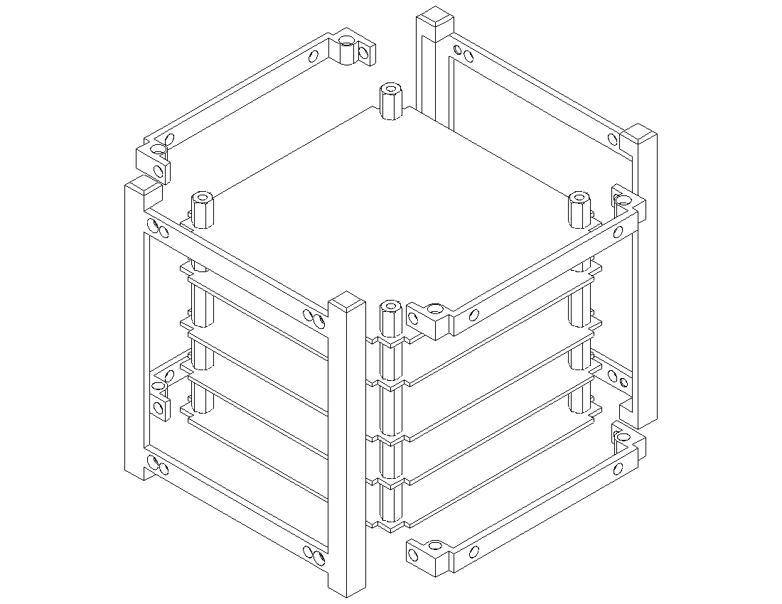
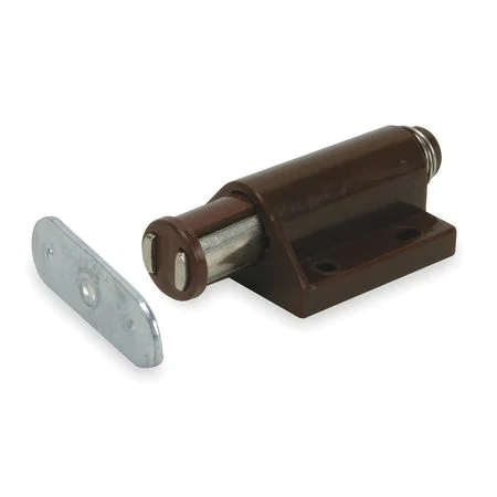
In my cubesat designs I use a central stack of PCBs with standoffs that provide the rigidity. I attach 4 rails to the stack and then 2 frames to the rails. The resulting cube is very rigid. By designing raised lips on the frame you could use magnetic catches within the frame and steel plates on the panels. The panels could be placed on the catches and then pressed into the frame. The lips would hold the panel from moving and provide a flush appearance. In this design any panel could be removed.
The latest release of the P2 LED Matrix driver supports our new 64x64 panels. (See Releases page)
This has also been released to our P2 Obex.
This version of the driver has been tested with two panels comprising a 128x64 display. I'm waiting on more panels before we can confirm it working with the 6 panels we need for this cube design.
I have had a full plate lately with work and home, vaccines and trying to stay warm, but I'll be active here again soon. Here is a basic update from my end:
The basic model is ready, although I haven't been able to record the assembly instructions I wanted. I also have ordered the parts to do the vertical flip on the square p2-es, although the pins aren't long enough for the HUB75 board (going through the PCB makes the fit less, and that is the only orientatation that offers a simple "bend" of the pins). I'll probably cobble something together with local supplies using the pin header parts.
I'll try to get a better update here within the next few days, or much more on the weekend.
I've started publishing this project in a github repository for now. It is there in it's current state with the STL models and some of the build instructions.
There is still more to do, but at least this way we can share the progress and status and allow for contributors to join in if they want to.
The contents of the repo will be given over to Parallax when the time is right to augment any kit instructions they have. We'll sort that out when the time is right.
Fantastic project, I ordered almost all of the parts.
My 3D printer is already printing.
I'm really looking forward to your assembly video, wiring and programming of the P2.
Can someone please give me a link to the P2 Pannels?
I'm assembling the printed parts and I noticed that I actually need 16x instead of 8x magnet joint flanges, right? And this also means 32 and not 16 magnets.
Or am I wrong? (4x sidepannels = 8 an top panel 8)
The panels are these: https://www.aliexpress.com/item/32967082722.html?spm=a2g0s.9042311.0.0.27424c4dCdqf4c
However, I'm pretty sure Ken will be listing some on the Parallax site relatively soon. I don't have details, but we can ask!
The insert is custom designed to protect the back of these PCB layouts. Other inserts can be designed as needed for different PCB layouts, but it's probably easier just to stick with these.
On the magnet flanges, you are correct. This should be 32 magnets.
So far, the assembly has gone very well!
I'm done with gluing, but I'm still waiting for the panels. (these should be sent out next week)
I can only assemble the frame when the panels are in.
Otherwise I already have all the items from the list. (The P2 Eval HUB75 adapter board is on the way to me and should arrive on Monday)
Am I right? Rotate each side part by 90 °? So that it fits together?
How can I support the project? And is it already clear which program is being used on the P2 board?
Already have 2 friends who want to build the cube if everything works.
Yes, each panel is rotated so that all12 edges have a rail. And yes, you will find that once the panel PCBs are added to the frames, they become much more structurally sound.
As far as the code goes, this is not done yet. I've had lots of things happening lately so I've had to switch gears for a bit. But I plan on getting back to it as soon as things settle down.
This is honestly something that we'll probably all do together, those of us building these things. That is part of the fun of it.
In terms of what you can do to help, you're doing it! Sharing back your experiences, errata, and other details so we can make the project better for the next builders is really the best thing we can do right now.
Do you mind adding that image and explanation to the github? If you aren't a github user, I'm happy to add it with your permission, but if you are, I'm happy to accept PRs too.
The P2 will work with 6 panels. They daisy chain.
The panels you get should come with enough HUB75 ribbon cables to connect them all up.
I'm hoping to verify some wiring and demos this weekend.
@AndreasS said:
Hello, some News?
Will the P2 Board work with 6 panels?
Plans of wire and Programming the P2?
Comments
The through-hole post and glue method will drastically speed it up for the next time.
> I dropped a stock LED panel on the concrete floor while rearranging the workspace. This is now the official test panel. It's a good thing I anticipated my own clumsiness on this and bought 2 extras.
You are a wise man
The video looks awesome, so exciting to see it come together so quickly like that! Cant wait to see a final version!
BTW I have linked to this forum post from a pinned comment on my Video, once you have a final version ill link to it from the video description proper tho the views on the video have drastically slowed down so I dont know how many people will see it.
Also as I mentioned in my pinned comment, someone has taken my LED Cube Youtube vid, watermarked it, made up a bunch of fake screenshots then is trying to sell a fake cube with it
Was the mention of my name a typo here? I can't see any relevance.
Oh apologies! I meant @Twyyx
it is basically good to mention @RossH once in a while, being that far out in the nowhere, having to drive for a internet connection ...
And basically I also think that multiple HUB75 connections would be desirable.
Enjoy!
Mike
We do have an internet connection - but it is a slow and unreliable satellite service. We can mostly do basic browsing and email (although it requires you to have a bit of patience), but we cannot do video.
On the plus side, we often get positive reviews from guests who are trying to wean their kids off the internet!
I have done the second full frame build, this time with actual panels. This build incorporated refinements to the 3d models which made building much easier, although it takes a little longer with the joints. It's still just a couple hours. I learned some techniques that need to be folded into the build guide.
Once assembled with the magnetic top, I lost track of which was the top! I realized it needed to be marked with a couple pips on the plastic liner. Problem solved! It's nice that the fit is so close and consistent that you cant tell which side is the magnetic one.
I've been eager to get to this point. The interior design can be finished now. It's clear that the cables will all fit, and -- with a custom subframe that can snap into the interior edge holes, we can maximize the available space inside. This may even allow for some cuboid voids which are perfect places to slot the plastic packed lipo batteries into.
We're almost to the next challenge: Wiring things up and starting on the controller design/layout/programming. Once the interior subframe has been designed around the components I have on hand (P2/edge adapter/battery/PSU), I'll share all the files here and then we can start working on the electronics.
Looking forward to seeing what your plans are for the programming side of things.
Just pinging the thread to let people know I'm still here and plugging at this project when I can. Work has been quite busy lately, but I'll be back to this soon.
On Thursday, we're meeting to discuss the P2 P2 Cube assembly challenges: Wiring in a small space, also known as "Ask Michael for help on a PCB idea." Anybody who is interested in this project is welcome to come and join us.
Topic: HUB75 Cube Circuit Board!
Time: Feb 11, 2021 11:00 AM Mountain Time (US and Canada)
Join Zoom Meeting
https://us02web.zoom.us/j/81761732052?pwd=Y285ejEwUjh0cGRJSmtGcGhaT0NFdz09
Meeting ID: 817 6173 2052
Passcode: 521381
One tap mobile
+16699006833,,81761732052# US (San Jose)
+12532158782,,81761732052# US (Tacoma)
Dial by your location
+1 669 900 6833 US (San Jose)
+1 253 215 8782 US (Tacoma)
+1 346 248 7799 US (Houston)
+1 301 715 8592 US (Washington DC)
+1 312 626 6799 US (Chicago)
+1 646 876 9923 US (New York)
Meeting ID: 817 6173 2052
Find your local number: https://us02web.zoom.us/u/kepPEVUwch
Unfortunately thats going to be a bit too early in the morning for me (2am), looking forward to hearing the results tho!
P.S. Yes anything you can do to make the wiring better is a fantastic plan.
Sorry, @mikeysee , I should have been more specific. We may be asking a Parallax fellow/collaborator, whom is named Michael to help us. Anything we come up with I'll share back here.
Haha ye I thought as much .. there are too many people with the same awesome name in the world!
A couple of thoughts:
1) Just saw this: https://hackaday.io/project/177274-rgb-panel-clock-with-animation-and-sound
2) A time zone cube would be cool with each panel representing the appropriate timezone on the earth.
In my cubesat designs I use a central stack of PCBs with standoffs that provide the rigidity. I attach 4 rails to the stack and then 2 frames to the rails. The resulting cube is very rigid. By designing raised lips on the frame you could use magnetic catches within the frame and steel plates on the panels. The panels could be placed on the catches and then pressed into the frame. The lips would hold the panel from moving and provide a flush appearance. In this design any panel could be removed.


The latest release of the P2 LED Matrix driver supports our new 64x64 panels. (See Releases page)
This has also been released to our P2 Obex.
This version of the driver has been tested with two panels comprising a 128x64 display. I'm waiting on more panels before we can confirm it working with the 6 panels we need for this cube design.
Regards,
Stephen
Thanks for the update @"Stephen Moraco".
I have had a full plate lately with work and home, vaccines and trying to stay warm, but I'll be active here again soon. Here is a basic update from my end:
The basic model is ready, although I haven't been able to record the assembly instructions I wanted. I also have ordered the parts to do the vertical flip on the square p2-es, although the pins aren't long enough for the HUB75 board (going through the PCB makes the fit less, and that is the only orientatation that offers a simple "bend" of the pins). I'll probably cobble something together with local supplies using the pin header parts.
I'll try to get a better update here within the next few days, or much more on the weekend.
I'm pretty excited to get a hold of those LED matrix screens! Awesome work!
I've started publishing this project in a github repository for now. It is there in it's current state with the STL models and some of the build instructions.
There is still more to do, but at least this way we can share the progress and status and allow for contributors to join in if they want to.
The contents of the repo will be given over to Parallax when the time is right to augment any kit instructions they have. We'll sort that out when the time is right.
Here is the repo: https://github.com/jshook/p2_p2_cube
I'll continue finishing out these sections as I can, but now it is easy to see what the progress is.
Fantastic project, I ordered almost all of the parts.
My 3D printer is already printing.
I'm really looking forward to your assembly video, wiring and programming of the P2.
Can someone please give me a link to the P2 Pannels?
Thank you
Hello Twyyx,
I'm assembling the printed parts and I noticed that I actually need 16x instead of 8x magnet joint flanges, right? And this also means 32 and not 16 magnets.
Or am I wrong? (4x sidepannels = 8 an top panel 8)
The panels are these: https://www.aliexpress.com/item/32967082722.html?spm=a2g0s.9042311.0.0.27424c4dCdqf4c
However, I'm pretty sure Ken will be listing some on the Parallax site relatively soon. I don't have details, but we can ask!
The insert is custom designed to protect the back of these PCB layouts. Other inserts can be designed as needed for different PCB layouts, but it's probably easier just to stick with these.
On the magnet flanges, you are correct. This should be 32 magnets.
Please let me know how your assembly goes!
Hello,
So far, the assembly has gone very well!
I'm done with gluing, but I'm still waiting for the panels. (these should be sent out next week)
I can only assemble the frame when the panels are in.
Otherwise I already have all the items from the list. (The P2 Eval HUB75 adapter board is on the way to me and should arrive on Monday)
Am I right? Rotate each side part by 90 °? So that it fits together?

How can I support the project? And is it already clear which program is being used on the P2 board?
Already have 2 friends who want to build the cube if everything works.
Regards,
Andreas
Awesome!
Yes, each panel is rotated so that all12 edges have a rail. And yes, you will find that once the panel PCBs are added to the frames, they become much more structurally sound.
As far as the code goes, this is not done yet. I've had lots of things happening lately so I've had to switch gears for a bit. But I plan on getting back to it as soon as things settle down.
This is honestly something that we'll probably all do together, those of us building these things. That is part of the fun of it.
In terms of what you can do to help, you're doing it! Sharing back your experiences, errata, and other details so we can make the project better for the next builders is really the best thing we can do right now.
Do you mind adding that image and explanation to the github? If you aren't a github user, I'm happy to add it with your permission, but if you are, I'm happy to accept PRs too.
Jonathan
Hi Twyyx,
yes pls add this image to github.
Hello, some News?
Will the P2 Board work with 6 panels?
Plans of wire and Programming the P2?
Greetings
The P2 will work with 6 panels. They daisy chain.
The panels you get should come with enough HUB75 ribbon cables to connect them all up.
I'm hoping to verify some wiring and demos this weekend.
so far so good
