@tritonium said:
I am particularly interested in doing it sensorlessly.
Dave
Note this essential quotation from the section on that PDF on sensorless control:
"The motor must be moving at a minimum rate to
generate sufficient back EMF to be sensed" (top of page 9).
Yeah, you can start them sensorless, but they typically don't work well until up to a certain speed. If you need lots of low motion and direction changes, get sensors.
"If low cost is a primary concern and low speed motor
operation is not a requirement and the motor load is not
expected to change rapidly then sensorless control
may be the better choice for your application." (also top of page 9).
If any of those are requirements, then go with sensors.
And to be honest, hall-sensor equipped motors are not really expensive. A few dollars more, if that.
Also looking at those horrible waveforms it struck me why one of the big 3-phase drivers I have around here is actually a two-stage driver. There's a big fast MOSFET to do the PWM, which then runs through a big toroidal inductor (1" cube-ish, a bit squished) to six more FETs that merely do the six-step dance with what is now a nice clean voltage.
No, no currents, just measure the voltage at the virtual star point. The current is just a follow up of the voltage you apply, the speed and the resistance of the coil. Measuring the current is just cream on the cake
There is no need not to open-source a BLDC driver software, all are created equal, some are more equal. No solution I know starts under any torque at any position because the inital rotor position is not determined and any small movement can not be detect. Therefor the means of choise is brute force. Kick the motor and hope it starts. What mostly happens if there is no inertial load.
@ErNa said:
It is scientifically proven, the humble bee can not fly.
Not science, just a press statement ... based on an existing model. Like how it's been said black-holes have nothing inside. Obviously there's something still there to maintain the forces.
We had a really good discussion today on the P2 Zoom meeting at 1pm. Video will up later.
Rezam explained how to use the undriven coil (1 of three at any time) for phase sensing on zero crossing. We talked a lot towards the end of the meeting about how this all works, going over the fundamentals. None of us started out knowing much, but we were able to reason things out pretty well.
Stephen Moraco will probably lay out a generic BLDC driver board with 3-leg high/low/float drivers and voltage dividers for sensing U, V, and W. Also, a resistive summer for all three together. This will make it easy for any of us to experiment with these brushless motors.
Meanwhile, here are some graphics that are interesting, shared by Captain Quirk:
@Scroungre said:
There is, and it's called turbulence. It's also beastly difficult to mathematically model.
That's outside the event horizon. A somewhat different location.
Or maybe more importantly, irrespective of how deeply the turbulence can be modelled, it's just another effect of the forces coming from inside. So the turbulent is just more evidence of something still residing inside.
Doug and I have the shunt resistors providing current feedback through ADCs running synchronously with the PWM frame. It's quite precise-looking. Next, we need to see if we can resolve the magnet angle using this setup, which involves just the three wires going to the motor. Should this be possible without any angular movement? If we can somehow resolve the magnet angle, we will know our driving angle is either +90 or -90 relative degrees, and can only use as much duty (current) as needed. We can then close the loop.
We have been scouring the internet for information on field-oriented control, but all the videos only go so far before they either recommended a chip like the Trinamic products or they say that further information is beyond the scope of their video. Doug remembers seeing one video where a guy was doing it all, including tracking position, but that video is gone. Doug went back through six months of his YouTube history and could not find it. It seems like FOC implementation is a trade secret.
I don't know if that's the one you'be been looking for, but the following youtube channel has a lot of interesting stuff going on, about BLDCs...
P.S. It's easy to notice how such kind of control can be used, to craft a P1/P2 HUB operation demo, controled by P2. With the help of some leds, newcomers can "feel, hear and watch" the inner guts of either member of the Propeller "family"!
scolton.blogspot.com/ This guy has done a lot on motor control and it is really worth studying. Now he is active in video technology. But during time at the university he also made great things and had a lot of fun. Couldn't sparke his interest in the propeller, sorry. Look to the "motor control" link up in the right corner.
As I said: to understand motor control, you need a neuralizer and start from scratch..
The pictures I supplied were from posts by Takao Shimizu, on the RCGroups\
DIY electronics forum. Takao is a engineer interested in radio control airplanes
and boats. He has posted over a 1000 examples since 2002 to present, of AT90S2313,
C8051Fxxx assembly, and atmega328, teensy, stm32 Arduino C code, schematics,
and diagrams that explain his sensorless code strategies with the purpose tutoring
r/c & electronic hobbyists to make bldc esc's that are better than what is commonly
available from China.
He also posted guides for diy single phase brusheless, and 3 phase brushless inrunners,
and converting CD rom motors into model airplane motors before brusheless motors
were common. Needless to say, it isn't as convenient as an app note
Takao's sensorless bldc code has a unique feature that I have not seen in any
app notes. He uses the inductive kick that precedes the zero cross to help get the
correct commutation interval. The P2 should be good at this.
Bill M.
A quick shout out to Graham Stabler, who also posted bldc info @rcgroups,
and Parallax.
As I follow the discussion I have to state that I'm not understood. There is just to much knowledge around.
With the propeller we have a integrating ADC. When commutation takes place and the commutation spike vanishes, the floating phase changes from on level (the driving voltage) to another level (the negative) with a linear slope. The duration of this signal is exactly one sixth of a electrical rotation, independ of rotational speed and so inverse to speed. The amplitude of the voltage swing is proportional to the rotational speed. The integral of a signal proportional to speed over a time inverse to speed is a constant. So you read the adc counter every time you commutate and calculate the difference. If the result is equal every time, the commutation is perfect. If not, the result is positive or negative, the commutation was early or late.
This may be familiar to the rf guys as it's just the functionality of a PLL or a phase discriminator.
Doing this, you have no longer to care about any zero crossing of any signal, you measure the signal in all its beauty, integrating (and so: filtering noise) all the the time the signal is present. More information you can not gain.
I'm not presenting any code hear, because it make no sense to understand code if the princip of the code is still not fully understood. ;-)
In the meantime it may be worth reading: https://ti.com/lit/an/sprt703/sprt703.pdf
TI developed "InstaSpin" that should be able to start any motor with brute force and then switch to InstaSpin. They also integrate the floating signal, and wait until a certain value is reached to commutate. Then the signal is reset. The foundations of InstaSpin are the best I found in any application note and I read more of them then a president call tell lies.
We all know, the internet doesn't forget! Not only this, the internet gives a platform to promote ancient greek knowledge and keeps it alive into the time of nanotechnology. Nano = dwarf. But a lot of knowledge was falsified. And is still promoted anyway. So the Greek thought, that there has to be a force to create uniform motion. Because they didn't know the concept of friction. And this knowledge is promoted in the first video (episode 7) at 5:55. And that is just the most simple case to point to a missconception, these videos are full off.
The current slope in an inductance is linear, not curved like in the videos. Both for increase and decay. What is shown is the serial connection of an inductance with a high valued resistor what will result in a motor efficiency less 50%, what nobody really wants.
Invest in Neuralizer companies ! There is a huge market!
Even as I knew, it will hurt me, I watched the episode 8 and yes, I'm not a masochist, it hurted. Without already knowing the transform for an layman it is impossible to follow. This is just Siegfried and Roy.
I know, billions of motors are running. But that's due to the fact, that in practice nearly impossible not to run a motor.
The concept of a BLDC motor is to design a electro mechanical arrangement that created constant force when moving over a certain angle. That allows to control the motor just with three hall sectors. As saturation means: the iron can no longer create more magnetic flux when there is more current, and as the iron saturated first in the pole edges, as it concentrated there to create the torque, the iron vanishes for the magnetic field so the active geometry of the motor changes! So a motors design is meant to optimize the motors performance under specific condition. That's the reason there is not on design, a myriad. And the most influencial factor is production cost.
If Parallax wants to make a motor controller: make the most simple hall commutated design or a simple sensorless design like in an EVC, which is very primitive, and sell it in masses to the mass applications. But it will be impossible to compete the current manufacturers. The P2's power will allow to make the most performant motor controller thinkable, but that will just give some promotion to the P2, in mass production much cheaper chips will do the jobs. But to do earnest research work (not just search)
1) A brushless motor drive accessory board for the P2 would be highly keen.
2) Forget the sensorless stuff. That's great for motors that run for hours in a constant direction (computer fans?) but not so much for motors that start, stop, and change direction now and then. Nobody's going to use a P2 to drive a fan motor. Hall sensors will do fine.
3) Put an encoder input connector on the board, and see about closing the servo loop (heheh. I might build one of those myself...). An absolute encoder would be even better than hall sensors, but would require unusual and expensive motors.
Ah, you don't know the main reason that's driving this round of imagination - Efficient flying drones, with their gaggle of prop motors. Sensorless makes a lot of sense in this single application. And not just at the hobby scale.
Doug and I have the shunt resistors providing current feedback through ADCs running synchronously with the PWM frame. It's quite precise-looking. Next, we need to see if we can resolve the magnet angle using this setup, which involves just the three wires going to the motor. Should this be possible without any angular movement?
Do you mean detect a fully stationary rotor ?
Expecting voltage feedback from a stationary rotor would be hoping Lenz's law did not apply
At very low angular movement, the hall sensors you mentioned would give some information (but likely with not great angular precision), and as speed increases you can extract the Lenz voltage, for better angle sense.
@Scroungre said:
Also looking at those horrible waveforms it struck me why one of the big 3-phase drivers I have around here is actually a two-stage driver. There's a big fast MOSFET to do the PWM, which then runs through a big toroidal inductor (1" cube-ish, a bit squished) to six more FETs that merely do the six-step dance with what is now a nice clean voltage.
Interesting approach. That would improve RFI, and lower system cost as there is a single fast power-switcher stage.
AC drives are variable voltage and variable frequency, and both need to track, so splitting the task into 'variable voltage' stage and then a tracking but simpler 'variable frequency' stage could be good for medium sized motors.
There will be more motor losses in this simpler driver, as the winding voltage will have more harmonics, but in many uses that is not so important.
@cgracey said:
Just heard from Doug. He said he attached a brushless DC motor from a model airplane and it turned super slowly.
...Now, he's got it running the hoverboard motor, which was the goal.
If the goal is precise angle control at low speed, you may need to also consider absolute angle errors in the mechanical side.
If you plot where you hoped to be over 360', vs where you actually were, that shows the mechanical and winding errors.
I recall high end laser printers used a EPROM with each motor, and that EPROM encoded the mechanical and winding errors and so made the scan much more linear.
Replacement motors came with a matching EPROM.
That's what good (high precision) position sensing gives you, is it tolerates the mechanical and winding errors.
Maybe the P2 is capable enough to do a polynomial correction, to avoid needing a large table storage ?
It still needs a calibrate stage, but maybe the more compact polynomial info can be stored in a QR label ?
@Scroungre said:
Also looking at those horrible waveforms it struck me why one of the big 3-phase drivers I have around here is actually a two-stage driver. There's a big fast MOSFET to do the PWM, which then runs through a big toroidal inductor (1" cube-ish, a bit squished) to six more FETs that merely do the six-step dance with what is now a nice clean voltage.
Interesting approach. That would improve RFI, and lower system cost as there is a single fast power-switcher stage.
Indeed. One of the reasons most people don't do that is because they want to use the motor windings themselves as the inductor. S.
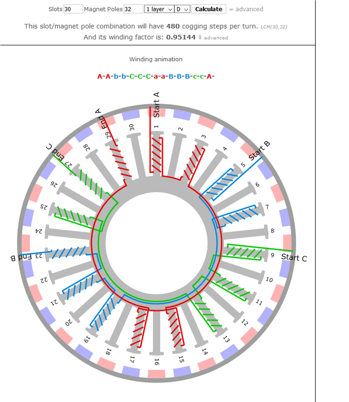
Since the HoverBoard motor has the potential of being a slow motor,
I am posting some Delta wound possibilities, and a general guide for
successful winding schemes for smaller motors from the old powercroco.de
web site
The first winding scheme is the classic LRK from ~2001, and the second
is the popular distributed-LRK.
Both winding schemes could be improved for speed by replacing the
32 magnets with 28.


Comments
Note this essential quotation from the section on that PDF on sensorless control:
"The motor must be moving at a minimum rate to
generate sufficient back EMF to be sensed" (top of page 9).
Yeah, you can start them sensorless, but they typically don't work well until up to a certain speed. If you need lots of low motion and direction changes, get sensors.
"If low cost is a primary concern and low speed motor
operation is not a requirement and the motor load is not
expected to change rapidly then sensorless control
may be the better choice for your application." (also top of page 9).
If any of those are requirements, then go with sensors.
And to be honest, hall-sensor equipped motors are not really expensive. A few dollars more, if that.
Also looking at those horrible waveforms it struck me why one of the big 3-phase drivers I have around here is actually a two-stage driver. There's a big fast MOSFET to do the PWM, which then runs through a big toroidal inductor (1" cube-ish, a bit squished) to six more FETs that merely do the six-step dance with what is now a nice clean voltage.
S.
No, no currents, just measure the voltage at the virtual star point. The current is just a follow up of the voltage you apply, the speed and the resistance of the coil. Measuring the current is just cream on the cake
It was my understanding the Odrive is 100% open source but I haven't delved too deep.
odriverobotics.com
There is no need not to open-source a BLDC driver software, all are created equal, some are more equal. No solution I know starts under any torque at any position because the inital rotor position is not determined and any small movement can not be detect. Therefor the means of choise is brute force. Kick the motor and hope it starts. What mostly happens if there is no inertial load.
Not science, just a press statement ... based on an existing model. Like how it's been said black-holes have nothing inside. Obviously there's something still there to maintain the forces.
There is, and it's called turbulence. It's also beastly difficult to mathematically model.
We had a really good discussion today on the P2 Zoom meeting at 1pm. Video will up later.
Rezam explained how to use the undriven coil (1 of three at any time) for phase sensing on zero crossing. We talked a lot towards the end of the meeting about how this all works, going over the fundamentals. None of us started out knowing much, but we were able to reason things out pretty well.
Stephen Moraco will probably lay out a generic BLDC driver board with 3-leg high/low/float drivers and voltage dividers for sensing U, V, and W. Also, a resistive summer for all three together. This will make it easy for any of us to experiment with these brushless motors.
Meanwhile, here are some graphics that are interesting, shared by Captain Quirk:
That's outside the event horizon. A somewhat different location.
Or maybe more importantly, irrespective of how deeply the turbulence can be modelled, it's just another effect of the forces coming from inside. So the turbulent is just more evidence of something still residing inside.
I don't know if that's the one you'be been looking for, but the following youtube channel has a lot of interesting stuff going on, about BLDCs...
https://youtube.com/channel/UCRd9x4pmbc09_RXTrkSY2Gg
P.S. It's easy to notice how such kind of control can be used, to craft a P1/P2 HUB operation demo, controled by P2. With the help of some leds, newcomers can "feel, hear and watch" the inner guts of either member of the Propeller "family"!
scolton.blogspot.com/ This guy has done a lot on motor control and it is really worth studying. Now he is active in video technology. But during time at the university he also made great things and had a lot of fun. Couldn't sparke his interest in the propeller, sorry. Look to the "motor control" link up in the right corner.
As I said: to understand motor control, you need a neuralizer and start from scratch..
The pictures I supplied were from posts by Takao Shimizu, on the RCGroups\
DIY electronics forum. Takao is a engineer interested in radio control airplanes
and boats. He has posted over a 1000 examples since 2002 to present, of AT90S2313,
C8051Fxxx assembly, and atmega328, teensy, stm32 Arduino C code, schematics,
and diagrams that explain his sensorless code strategies with the purpose tutoring
r/c & electronic hobbyists to make bldc esc's that are better than what is commonly
available from China.
He also posted guides for diy single phase brusheless, and 3 phase brushless inrunners,")
and converting CD rom motors into model airplane motors before brusheless motors
were common. Needless to say, it isn't as convenient as an app note
Takao's sensorless bldc code has a unique feature that I have not seen in any
app notes. He uses the inductive kick that precedes the zero cross to help get the
correct commutation interval. The P2 should be good at this.
Bill M.
A quick shout out to Graham Stabler, who also posted bldc info @rcgroups,
and Parallax.
As I follow the discussion I have to state that I'm not understood. There is just to much knowledge around.
With the propeller we have a integrating ADC. When commutation takes place and the commutation spike vanishes, the floating phase changes from on level (the driving voltage) to another level (the negative) with a linear slope. The duration of this signal is exactly one sixth of a electrical rotation, independ of rotational speed and so inverse to speed. The amplitude of the voltage swing is proportional to the rotational speed. The integral of a signal proportional to speed over a time inverse to speed is a constant. So you read the adc counter every time you commutate and calculate the difference. If the result is equal every time, the commutation is perfect. If not, the result is positive or negative, the commutation was early or late.
This may be familiar to the rf guys as it's just the functionality of a PLL or a phase discriminator.
Doing this, you have no longer to care about any zero crossing of any signal, you measure the signal in all its beauty, integrating (and so: filtering noise) all the the time the signal is present. More information you can not gain.
I'm not presenting any code hear, because it make no sense to understand code if the princip of the code is still not fully understood. ;-)
In the meantime it may be worth reading: https://ti.com/lit/an/sprt703/sprt703.pdf
TI developed "InstaSpin" that should be able to start any motor with brute force and then switch to InstaSpin. They also integrate the floating signal, and wait until a certain value is reached to commutate. Then the signal is reset. The foundations of InstaSpin are the best I found in any application note and I read more of them then a president call tell lies.
Good stuff here. I benefited greatly from a video this paper led me to find at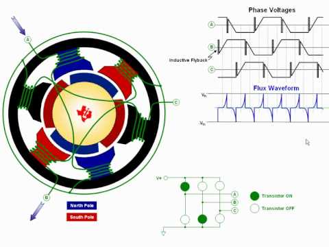
Hi
THAT was REALLY interesting! (the video I mean)
Can't wait to see what others have to say...
Dave
Erna, thanks. That last bit of info you gave is most understandable and applicable.
In there I see three named methods: Scalar Control, Field Oriented Control, and Direct Torque Control.
Erna,
Does yours fit as one of those?
No, it's origional research. Like the Propeller and only possible with the Propeller!
Found some short, easy to digest videos
How does the way you PWM switch affect commutation? (Episode 7) 11:08 min
The Clarke and Park transformations (Episode 8) 9:02 min
Why is sinusoidal current best in a DC motor?? (Episode 9) 8:26 min
(Neat Stuff) What is Space Vector Modulation? (Episode 10) 10:53 min
(Neat Stuff) How to do Space Vector Modulation (Understanding Motors episode 11) 11:03
Bill M.
We all know, the internet doesn't forget! Not only this, the internet gives a platform to promote ancient greek knowledge and keeps it alive into the time of nanotechnology. Nano = dwarf. But a lot of knowledge was falsified. And is still promoted anyway. So the Greek thought, that there has to be a force to create uniform motion. Because they didn't know the concept of friction. And this knowledge is promoted in the first video (episode 7) at 5:55. And that is just the most simple case to point to a missconception, these videos are full off.
The current slope in an inductance is linear, not curved like in the videos. Both for increase and decay. What is shown is the serial connection of an inductance with a high valued resistor what will result in a motor efficiency less 50%, what nobody really wants.
Invest in Neuralizer companies ! There is a huge market!
Even as I knew, it will hurt me, I watched the episode 8 and yes, I'm not a masochist, it hurted. Without already knowing the transform for an layman it is impossible to follow. This is just Siegfried and Roy.
I know, billions of motors are running. But that's due to the fact, that in practice nearly impossible not to run a motor.
The concept of a BLDC motor is to design a electro mechanical arrangement that created constant force when moving over a certain angle. That allows to control the motor just with three hall sectors. As saturation means: the iron can no longer create more magnetic flux when there is more current, and as the iron saturated first in the pole edges, as it concentrated there to create the torque, the iron vanishes for the magnetic field so the active geometry of the motor changes! So a motors design is meant to optimize the motors performance under specific condition. That's the reason there is not on design, a myriad. And the most influencial factor is production cost.
If Parallax wants to make a motor controller: make the most simple hall commutated design or a simple sensorless design like in an EVC, which is very primitive, and sell it in masses to the mass applications. But it will be impossible to compete the current manufacturers. The P2's power will allow to make the most performant motor controller thinkable, but that will just give some promotion to the P2, in mass production much cheaper chips will do the jobs. But to do earnest research work (not just search)
IM (not so) HO:
1) A brushless motor drive accessory board for the P2 would be highly keen.
2) Forget the sensorless stuff. That's great for motors that run for hours in a constant direction (computer fans?) but not so much for motors that start, stop, and change direction now and then. Nobody's going to use a P2 to drive a fan motor. Hall sensors will do fine.
3) Put an encoder input connector on the board, and see about closing the servo loop (heheh. I might build one of those myself...). An absolute encoder would be even better than hall sensors, but would require unusual and expensive motors.
S.
Ah, you don't know the main reason that's driving this round of imagination - Efficient flying drones, with their gaggle of prop motors. Sensorless makes a lot of sense in this single application. And not just at the hobby scale.
If a drone propellor motor isn't a fan, I dunno what is! And yes, it would be so ironic to have a propeller chip running so many propellors... S.
Do you mean detect a fully stationary rotor ?")
Expecting voltage feedback from a stationary rotor would be hoping Lenz's law did not apply
At very low angular movement, the hall sensors you mentioned would give some information (but likely with not great angular precision), and as speed increases you can extract the Lenz voltage, for better angle sense.
Interesting approach. That would improve RFI, and lower system cost as there is a single fast power-switcher stage.
AC drives are variable voltage and variable frequency, and both need to track, so splitting the task into 'variable voltage' stage and then a tracking but simpler 'variable frequency' stage could be good for medium sized motors.
There will be more motor losses in this simpler driver, as the winding voltage will have more harmonics, but in many uses that is not so important.
The combination of the coarse rotor angle feedback plus current sensing allows for fine torque control. That's enough for the motor drive.
Finer grain positional feedback is often a separate motion control loop with its own encoder. Not needed for motor commutation.
If the goal is precise angle control at low speed, you may need to also consider absolute angle errors in the mechanical side.
If you plot where you hoped to be over 360', vs where you actually were, that shows the mechanical and winding errors.
I recall high end laser printers used a EPROM with each motor, and that EPROM encoded the mechanical and winding errors and so made the scan much more linear.
Replacement motors came with a matching EPROM.
That's what good (high precision) position sensing gives you, is it tolerates the mechanical and winding errors.
Maybe the P2 is capable enough to do a polynomial correction, to avoid needing a large table storage ?
It still needs a calibrate stage, but maybe the more compact polynomial info can be stored in a QR label ?
Indeed. One of the reasons most people don't do that is because they want to use the motor windings themselves as the inductor. S.
Since the HoverBoard motor has the potential of being a slow motor,
I am posting some Delta wound possibilities, and a general guide for
successful winding schemes for smaller motors from the old powercroco.de
web site
The first winding scheme is the classic LRK from ~2001, and the second
is the popular distributed-LRK.
Both winding schemes could be improved for speed by replacing the
32 magnets with 28.
Bill M.
There was a comment citing an early post. I got a notice but it was deleted. Did I get something wrong?
I just briefly saw the post in question. The offender was not you @ErNa.