@Mickster said:
Back in the days of brushed servo-drives, everything was straightforward; a few connections, a pot to scale the velocity, a pot to scale the tach feedback, an offset pot and a current limit....piece of cake.
...
Who cares about sensorless! Digital should have made life simpler but in this case, it's the opposite.
So true. My plan was to write some clever software where the good-old pots are replaced by GUI sliders and you could tune the servo by adjusting the sliders with "audible" feedback from the motor. Unfortunatelly, I'm effectively bankrupt, now. Not money-wise, I have more orders that I can handle, but time-wise. Procurement of hard-to-get electronic parts and feeding the P&P machine eats up all resources and all development has stopped.
@ManAtWork
I tried very hard but just couldn't resist .
This is the most synthetical, most beautiful and most informative description of the Park transformation I have ever seen.
Ever thought of a career as a university prfessor ? You would be extremely good !
I'm currently quit busy but will come back to this at weekend, so please feel free to tell what you want to know about motor control and be reminded: motor control and motion control are different subjects. ;-)
@Scroungre said:
If you really feel like getting clever, you can combine 'getting started' with the six-step Hall sensors, and then switch to position feedback* drive once you know where your phases are. That way you can have much better phase precision than those Hall sensors. Self-calibrating, too! S.
*Of course, an absolute encoder could do this without Hall sensing - once calibrated.
I think Chip meant the hall sensors are the sole position feedback they plan to use. ie: treat it as a super low res encoder.
@cgracey said:
The goal is to run the motor with position feedback. This particular motor has three high/low-output hall effect sensors to detect where you are in the commutation cycle. We are going to use those, since they are simple to read. For output, we generate a 3-phase angle of some power level. The rest is tracking in software.
If you only have the hall sensor feedback and no higher resolution encoder it is probably the easiest to ignore the exact waveform alltogether and drive the motor similar to a stepper motor. The BEMF waveforms of those motors are almost trapezoidal anyway. So you drive the windings at the top and bottom line of the trapezoid with a constant PWM voltage (proportionally to speed) and let the third terminal (which is somewhere at the slope of the trapezoids) float. You don't know the exact position where you are within the slope, anyway. At least not at very slow speeds where smooth transitions are desireable. I would use some sort of fade/blend over instead of a hard switching when the commutation state changes to avoid click noises and torque ripple. At medium and hich speed you can interpolate between the hall states and "guess" the current rotor angle to get higher position resolution.
Do you need torque control (like for the gas pedal of a vehicle) or speed control (to drive a fan or propeller)?
@ManAtWork You are absolutely right in stating: if you know the sextant ( wich is strictly linked to the hall sensors signal), the property of a properly designed BLDC-Motor is to create constant torque at constant current over 60° of rotation. And DC current means: current in at one terminal, out at another one, floating third.
At the commutation point (transition of a hall signal) you have to commutate the current from one phase to another. As ramping down is driven by applied voltage + BEMF and ramping up is driven by applied voltage - BEMF, there is alway a dip in active current which is inevitable.
To overcome this you need kind of continuous commutation, but that depends on motor design and the ability to determine the actual rotor position. But normaly you don't know either. There is a simple solution: accept a cheap solution or spend some money for a servo motor with incremental encoder. ..
@Mickster said:
Look out ST and Trinamic.....Prop2 is gonna eat your lunch
With P2, Trinamic chips aren't of much use. In fact, P2 is fast enough to run a sensorless position observer for stepper and BLDC motors that works at any speed, standstill included. So it's not merely "crash detection" but you can do proper coordinated motion where the least performing axis will automatically "pace" the rest of them, and if you stop one motor, they'll all stop. You can also run adaptation that will remove acoustic noise, based on real-time feedback.
OK, it's weekend and I promised to tell something about the famous Clarke/Park transform and what it is important for. I try to use both simple language and concepts. So please take some time to read carefully. A single phrase not understood the way it was meant will lead to a misconception. Forget what you know or ask somebody for a Neuralizer.
But I just had a little fight with the forum software: I proveread what I wrote and it was gone! Sorry, I have to come again.
@ErNa said:
But I just had a little fight with the forum software: I proveread what I wrote and it was gone! Sorry, I have to come again.
Demoralising when that happens. My stress level rises just before pressing the post button. I now try to remember to copy to clipboard before posting, or even previewing.
For unknown reasons, this little chapter persisted:
Let us start with a DC motor.
No. Let us start with a motor. A motor is a piece of equipment, that converts electrical energy to mechanical energy and vice versa. Under normal circumstances we will not look on energy, but on power. So: as a certain power acting over a certain time represents an amount of energy, what we write in short: E = P * t, or Joule = Watt * seconds, we can agree on: if the time is equal to one, the amount of power is equal to the amount of energy. So I will use the terms energy and power synonymously now and then, knowing the power and energy are different stuff.
A motor creates torque when there is a current and the torque is proportional to the current. Why? We know that current flow creates a magnetic field. No. The field is what we need to describe the magnetic flux. The amount of magnetic flux is proportional to the current. A straight wire with current creates a magnetic flux that is proportional to a magnetic conductance, in this simple case, the vacuum (or free air, if you like). Therefor the highest flux density is in approximity to the wire, as the circumference is the smallest here, and grows with distance, what increases the resistance, what we call in the case of magnetics "reluctance". So imagine to have such a wire and some constant current flowing and there is a certain amount of magnetic current we call flux. The reluctance of the vacuum determines the amount of flux. If by any means you reduce the reluctance, the electrical current will not change, but the magnetic flux will increase, The means can be just a piece of iron.
If a motor presents a magnetic flux equal to and opposite to that induced by current flowing through the coils, the motor shall not rotate. You may want to put a phase shift in here somewhere. S.
That is, incidentally, how single-phase AC motors start; by deliberately delaying half a phase with an inline capacitor, which is then centrifugally thrown out of the circuit. Without that cap and switch, you put power on them and they just hum and get hot. S.
Doug and I have the shunt resistors providing current feedback through ADCs running synchronously with the PWM frame. It's quite precise-looking. Next, we need to see if we can resolve the magnet angle using this setup, which involves just the three wires going to the motor. Should this be possible without any angular movement? If we can somehow resolve the magnet angle, we will know our driving angle is either +90 or -90 relative degrees, and can only use as much duty (current) as needed. We can then close the loop.
We have been scouring the internet for information on field-oriented control, but all the videos only go so far before they either recommended a chip like the Trinamic products or they say that further information is beyond the scope of their video. Doug remembers seeing one video where a guy was doing it all, including tracking position, but that video is gone. Doug went back through six months of his YouTube history and could not find it. It seems like FOC implementation is a trade secret.
Doug and I have the shunt resistors providing current feedback through ADCs running synchronously with the PWM frame. It's quite precise-looking. Next, we need to see if we can resolve the magnet angle using this setup, which involves just the three wires going to the motor. Should this be possible without any angular movement? If we can somehow resolve the magnet angle, we will know our driving angle is either +90 or -90 relative degrees, and can only use as much duty (current) as needed. We can then close the loop.
I would say tricky, but probably not impossible, really. The problem is that to find one 'sensing' phase, you need to put current into another phase - which will cause the motor to rotate. A brake might help.
Also it's possible to throw in very fast current spikes such that the inertia of the motor and stiction in the bearings allows you to throw in current without rotation, but still be detectable.
Personally, I'd not recommend it. S.
It'll not solve all challenges without creating some new ones, e.g., EMC-compatibility testing issues, and induced torque ripple, as explainned at the following whitepaper, from Toshiba (starting on page 06):
"Achieving Low-Noise, Sensorless Field-Oriented Motor Control":
Doug went back through six months of his YouTube history and could not find it. It seems like FOC implementation is a trade secret.
Don't look for FOC, instead search for sensored, or sensorless bldc motor control.
FOC is one of many sensorless bldc motor control configurations,
It would help to learn the difference between an inrunner and an outrunner.
Bill M.
Don't look for sensorless bldc motor control. Running the motor is the most simple task, with or without sensor. Starting is also simple, but not with the methods proposed in public. So if you need to start a motor under unknown load, use hall sensors. If you know the speed of the motor by any means, apply the voltage the motor needs to run at this speed (it's the motors BEMF constant) and add some extra voltage to compensate the voltage drop at the resistance of the windings. The voltage drop equals winding resistance (take into account temperature coefficient of copper) times current to create torque (Its the motors Torque constant). There is no need for any headage at all. Don't use any sophisticated problem generator.
The HoverBoard already has what it needs to easily start and run. It is either equipped
with hall sensors, or not.
@"Capt. Quirk" said:
Don't look for FOC, instead search for sensored, or sensorless bldc motor control.
If you are looking for information on how operate a bldc motor, there is more
information available if the internet search is for sensored, or sensorless bldc
motor control vrs looking for FOC.
Bill M.
@cgracey said:
Erna, can you explain the Clarke/Park thing so that any of us could understand? Or, maybe you've already done that here.
OK, as you are asking: I wanted to show an interesting fact about three phase AC (3PhAC) etc in more detail, but as the editor ate my text, I only present the short version.
In a certain aspect, 3PhAC is DC. Upps, I heard many say, everything ripples! I'll explain: DC at constant current and constant voltage delivers constant power. So does 3PhAC. How can it be, as there is never anything constant at 3PhAC. We know that the sum of voltages in a mesh adds up to zero, what is the case for the 3 phases voltage to. The voltages in focus are sine. If there is ohmic load, the current is proportional to the voltage and the power is V * I = V * V / R = V² * R.
Now answer the question: what is the square of a sine?
Start with 0 at 0°: 0, goto 1/sqrt(2) at 45°: 1/2, step on to 1 at 90°: 1, etc: 135° 1/sqrt(2): 1/2, 180° : 0, 225° -1/sqrt(2) : 1/2 Upps: the negative voltage gives a positive square! Take a pen and do it yourself. What we learn: the square of a sine sin(f) is 1/2 - 1/2 cos (2f). A minus cosine of doubled frequency, half the amplitude and an offset of 1/2. Now look at the second phase. You get the same result, but as the original signal is shifted by 120°, the power is shifted by 240°. Look at the third phase, the phase shift 240° is doubled to 480° = 360° + 120°. Surprise! The three power signals are also phase shifted by 120°, into the opposite direction, but that doesn't change the fact, that the cosines sum up to zero. but we still have 3 times the offset value, so the power is a constant 1.5!
A 3PhAC delivers constant power as does DC!
I hope this was simple enough to follow, now it's going to be even more simple. But you should know some basic vector calculus.
There is something called the "space vector" https://www.sciencedirect.com/topics/engineering/space-vector that describes 3PhAC. I do not know, why this is done, but that's state of the art.
Imagine you have three phase voltages. U, V, W where U + V + W = 0. Then it is true: U * 1 + V * 1 + W * 1 = 0. If you remember vector calculus, the Dot Product of two vectors is zero whenever they are perpendicular. So we can write (A, B, C ) * (1, 1, 1) = 0. The vector 1 shows the diagonal of a cube. And a set of vectors perpendicular to a given one is located in a plane. So now you easily can see the 3PhAC as a vector of certain length (the voltage) and a certain phase angle. The Clarke-Transform does exactly the same, the difference: it's high tech only understood by geniuses.
Now it should be easily seen, that the same procedure can be applied to the phase currents, as they also sum up to zero in a node.
Let us ponder about what we actually want to reach? We want to run a motor. There are two starting conditions: the motor runs and we have to keep him running or the motor stops and we have to start him. As the first should be more simple, we take this task.
It's, we want to feed energy to the motor that goes to the wheel. This is active power where current and voltage have to be in phase. The motor is running and we apply a voltage of the right value and the right phase angle/velocity. There is a certain current, also with value and angle.
NO.
The point is, we can not command the motors voltage, e.g. BEMF. We only are free to drive a certain current to the motor to create torque. Thats what we do. The motors response is a voltage proportional to speed which we have to overcome by applying a EMF. This EMF is our PWM-Signal. To have the motor running constantly, the current has to be constant. If however we apply the wrong voltage (in value or more influential in phase), the current will change in a moment. That signals us that we made a wrong estimation of the motors condition we now can correct by instantly applying the correct voltage. That's how motor control works.
Now let us start the motor. We have to know the rotor position by any means, maybe by an conventional sensor or by using the motor itself as a sensor. We apply a voltage, just to drive the current into the coils and to overcome the resistance. at the right phase. The motor creates torque and starts to run, we have to follow with the angle and increase the voltage to overcome the BEMF.
That's motor control in short.
Now what does the Park transform? Up to now we talked about the real power we have to bring to the motor. What about reactive power?
Now the motor has terminals and we drive current. There is only one current in a terminal. But this current has two jobs to do: bring energy to the wheel and create a magnetic field. The voltage we apply can be separated into two parts that are shifted in phase by 90°. The actual values of the two components determine the cos phi. It depends on the motors internal design what the cos phi has to be. The Park transform brings the rotating vectors of current and voltage to a coordinate system at standstill that allows to calculate the phase angle.
Can it be a little more simple?
I think so: We know the voltage we apply. By phase and value, as we set the voltage. We know the current resulting from the voltage as we have to measure the current to control torque. So all we have to do is to normalize current and calculate Iu * Vu + Iv * Vv + Iw * Vw. That again is a Dot Product and the resulting value is cos Phi. If cos phi is to small, we increase the phase velocity of the EMF, else, we decrease the phase speed.
Not simple enough?
OK Cos phi is 1, whenever voltage and current are in phase. And zero, when orthogonal. So if I rotate current or voltage by 90° and Dot Product current to voltage, the value is zero when in phase and nonzero if not. That means: the sign of this calculation tells if phase has to be increased or decreased and to control a certain phase, this value has just to be added.
Conclusio: there is no need for a Clarke-Park-Transform. You just measure current in the three phases, multiply by the voltage in the three phase, add up and you know cos Phi. If to small, increase the phase angle increment by one, if to great, decrease the phase angle increment. If your motor runs at a given speed and your phase angle is not synchronized, the motor will stall within milliseconds. Your PWM runs at 20 kHz. Let the resolution of the phase angle be 20,000. The rotational speed is 3000/min == 50/sec. You have 400 PWM cycles per revolution, thats about one PWM cycle per degree. Your phase angle increment must be about 50. If your increment is just 1 of target, 90° of error will add up within 100 ms and you motor will stall.
To do some experiments: take a PMSM motor, run it with an encoder, calculate the phase angle from observing voltage and current, and look for the deviation of measured and estimated angle. If they are close, switch over to estimation and you run sensorlessly
Theory is only a value when validated in practise. So here we see what is called the BEMF at the floating terminal of a BLDC motor. This motor has some design flaws as the edges are rounded what points to a tick in torque produced. You see the shadows in the analog screen of spikes and other "noise"
And from all the noise you can extract so much more of information:
This is all done with the P1, and using the P1's ADC
I worked for this for some years and some years ago. All the research was done using a P1 and a resistor and a capacitor at an input pin :-) For about 90% of all BLDC's all information in in the signal they call "BEMF". Just connect three resistors to form a virtuel star-point, level shift the signal to an appropriate value using a potentiometer, thats it.
This is incredibly interesting to me- but the 'secrets' to driving BLDC motor seem to be cloaked in difficult to penetrate language and concepts.
I found the attached application note from microchip fascinating and would like your opinion.
Since high current bldc motor speed controllers are available cheaply for radio control models, it must be doable for hobbyest dabblers like me...
I am particularly interested in doing it sensorlessly.
It is scientifically proven, the humble bee can not fly. As she doen't know it, she flyes anyway. What we see in the paper is mostly applicable, it's not completely understood. For example shifts the signal at the virtual star point according to the voltage drop due the resistance of the winding. Running a BLDC is really simple as long as there is a lower bound of speed reached. When it comes to efficiency -chasing the last percent- ist becomes more sophisticated.
Cheap model ESC (electronic speed control) units don't PWM the outputs separately and synchronized with the commutation, the have a free running PWM and just commutate. But for finding "zero-crossing" at the higher speed, thats good enough. Model cars or planes are not used at lower speed ;-)
The point is: at higher speed, the motor is a balistic system, that is: nothing changes quickly and any mistake in control can be accepted for some time, so running a motor really is simple. It's harder to do this at low speed. Imagine the crowd at a traffic light waiting for green: the second to start has to eat the dust of the first. Therefor they run the standing motor from the full battery voltage, driving about 5 times the saturation current and even the hall sensor signals shift by 30°, so the motor stutters. It is possible to start such a motor even under those conditions sensorlessly if you know how. But who cares. ..
By the way: app note like that one are around in masses. For decades you find the same theory and minor improvement, but there is no game changer on the road.
Hi ErNa,
I tried to follow your thoughts. Do I get this right: You suggest to use the three winding currents together with their voltages? So for this you need 3 shunts to measure the currents?
Best regards Christof


Comments
So true. My plan was to write some clever software where the good-old pots are replaced by GUI sliders and you could tune the servo by adjusting the sliders with "audible" feedback from the motor. Unfortunatelly, I'm effectively bankrupt, now. Not money-wise, I have more orders that I can handle, but time-wise. Procurement of hard-to-get electronic parts and feeding the P&P machine eats up all resources and all development has stopped.
@ManAtWork") .
.
I tried very hard but just couldn't resist
This is the most synthetical, most beautiful and most informative description of the Park transformation I have ever seen.
Ever thought of a career as a university prfessor ? You would be extremely good !
I'm currently quit busy but will come back to this at weekend, so please feel free to tell what you want to know about motor control and be reminded: motor control and motion control are different subjects. ;-)
I think Chip meant the hall sensors are the sole position feedback they plan to use. ie: treat it as a super low res encoder.
If you only have the hall sensor feedback and no higher resolution encoder it is probably the easiest to ignore the exact waveform alltogether and drive the motor similar to a stepper motor. The BEMF waveforms of those motors are almost trapezoidal anyway. So you drive the windings at the top and bottom line of the trapezoid with a constant PWM voltage (proportionally to speed) and let the third terminal (which is somewhere at the slope of the trapezoids) float. You don't know the exact position where you are within the slope, anyway. At least not at very slow speeds where smooth transitions are desireable. I would use some sort of fade/blend over instead of a hard switching when the commutation state changes to avoid click noises and torque ripple. At medium and hich speed you can interpolate between the hall states and "guess" the current rotor angle to get higher position resolution.
Do you need torque control (like for the gas pedal of a vehicle) or speed control (to drive a fan or propeller)?
@ManAtWork You are absolutely right in stating: if you know the sextant ( wich is strictly linked to the hall sensors signal), the property of a properly designed BLDC-Motor is to create constant torque at constant current over 60° of rotation. And DC current means: current in at one terminal, out at another one, floating third.
At the commutation point (transition of a hall signal) you have to commutate the current from one phase to another. As ramping down is driven by applied voltage + BEMF and ramping up is driven by applied voltage - BEMF, there is alway a dip in active current which is inevitable.
To overcome this you need kind of continuous commutation, but that depends on motor design and the ability to determine the actual rotor position. But normaly you don't know either. There is a simple solution: accept a cheap solution or spend some money for a servo motor with incremental encoder. ..
With P2, Trinamic chips aren't of much use. In fact, P2 is fast enough to run a sensorless position observer for stepper and BLDC motors that works at any speed, standstill included. So it's not merely "crash detection" but you can do proper coordinated motion where the least performing axis will automatically "pace" the rest of them, and if you stop one motor, they'll all stop. You can also run adaptation that will remove acoustic noise, based on real-time feedback.
@kuba
Oh sure, aka: electronic gearing.
i actually wasn't referring to Trinamic's stepper motor products; they also offer advanced servo motor controllers.
OK, it's weekend and I promised to tell something about the famous Clarke/Park transform and what it is important for. I try to use both simple language and concepts. So please take some time to read carefully. A single phrase not understood the way it was meant will lead to a misconception. Forget what you know or ask somebody for a Neuralizer.
But I just had a little fight with the forum software: I proveread what I wrote and it was gone! Sorry, I have to come again.
Demoralising when that happens. My stress level rises just before pressing the post button. I now try to remember to copy to clipboard before posting, or even previewing.
For unknown reasons, this little chapter persisted:
Let us start with a DC motor.
No. Let us start with a motor. A motor is a piece of equipment, that converts electrical energy to mechanical energy and vice versa. Under normal circumstances we will not look on energy, but on power. So: as a certain power acting over a certain time represents an amount of energy, what we write in short: E = P * t, or Joule = Watt * seconds, we can agree on: if the time is equal to one, the amount of power is equal to the amount of energy. So I will use the terms energy and power synonymously now and then, knowing the power and energy are different stuff.
A motor creates torque when there is a current and the torque is proportional to the current. Why? We know that current flow creates a magnetic field. No. The field is what we need to describe the magnetic flux. The amount of magnetic flux is proportional to the current. A straight wire with current creates a magnetic flux that is proportional to a magnetic conductance, in this simple case, the vacuum (or free air, if you like). Therefor the highest flux density is in approximity to the wire, as the circumference is the smallest here, and grows with distance, what increases the resistance, what we call in the case of magnetics "reluctance". So imagine to have such a wire and some constant current flowing and there is a certain amount of magnetic current we call flux. The reluctance of the vacuum determines the amount of flux. If by any means you reduce the reluctance, the electrical current will not change, but the magnetic flux will increase, The means can be just a piece of iron.
If a motor presents a magnetic flux equal to and opposite to that induced by current flowing through the coils, the motor shall not rotate.") You may want to put a phase shift in here somewhere. S.
You may want to put a phase shift in here somewhere. S.
That is, incidentally, how single-phase AC motors start; by deliberately delaying half a phase with an inline capacitor, which is then centrifugally thrown out of the circuit. Without that cap and switch, you put power on them and they just hum and get hot. S.
Lots of interesting talk here.
Doug and I have the shunt resistors providing current feedback through ADCs running synchronously with the PWM frame. It's quite precise-looking. Next, we need to see if we can resolve the magnet angle using this setup, which involves just the three wires going to the motor. Should this be possible without any angular movement? If we can somehow resolve the magnet angle, we will know our driving angle is either +90 or -90 relative degrees, and can only use as much duty (current) as needed. We can then close the loop.
We have been scouring the internet for information on field-oriented control, but all the videos only go so far before they either recommended a chip like the Trinamic products or they say that further information is beyond the scope of their video. Doug remembers seeing one video where a guy was doing it all, including tracking position, but that video is gone. Doug went back through six months of his YouTube history and could not find it. It seems like FOC implementation is a trade secret.
No idea if this helps, but in the multi rotor community this is making waves: https://github.com/AlkaMotors/AM32-MultiRotor-ESC-firmware - maybe the project can provide some insights.
Don't look for FOC, instead search for sensored, or sensorless bldc motor control.
FOC is one of many sensorless bldc motor control configurations,
It would help to learn the difference between an inrunner and an outrunner.
Bill M.
I would say tricky, but probably not impossible, really. The problem is that to find one 'sensing' phase, you need to put current into another phase - which will cause the motor to rotate. A brake might help.
Also it's possible to throw in very fast current spikes such that the inertia of the motor and stiction in the bearings allows you to throw in current without rotation, but still be detectable.
Personally, I'd not recommend it. S.
It'll not solve all challenges without creating some new ones, e.g., EMC-compatibility testing issues, and induced torque ripple, as explainned at the following whitepaper, from Toshiba (starting on page 06):
"Achieving Low-Noise, Sensorless Field-Oriented Motor Control":
https://eenewseurope.com/sites/default/files/documents/whitepapers/tcm0568_a_low-speed_sensorless.pdf?token=%7Bcontactfield=hashmail%7D
Notewhorthy, on page 08, a method to overcome those problems is depicted (though poorly detailed): "Symmetric carrier PWM Method".
No one seems to be giving free lunchs, anymore, mainly when they come at the expense of their own...
Don't look for sensorless bldc motor control. Running the motor is the most simple task, with or without sensor. Starting is also simple, but not with the methods proposed in public. So if you need to start a motor under unknown load, use hall sensors. If you know the speed of the motor by any means, apply the voltage the motor needs to run at this speed (it's the motors BEMF constant) and add some extra voltage to compensate the voltage drop at the resistance of the windings. The voltage drop equals winding resistance (take into account temperature coefficient of copper) times current to create torque (Its the motors Torque constant). There is no need for any headage at all. Don't use any sophisticated problem generator.
And do not think in terms of FOC if you are not able to show, what the Clarke/Park transform says a way anybody can follow easily.
Erna, can you explain the Clarke/Park thing so that any of us could understand? Or, maybe you've already done that here.
The HoverBoard already has what it needs to easily start and run. It is either equipped
with hall sensors, or not.
If you are looking for information on how operate a bldc motor, there is more
information available if the internet search is for sensored, or sensorless bldc
motor control vrs looking for FOC.
Bill M.
++1
OK, as you are asking: I wanted to show an interesting fact about three phase AC (3PhAC) etc in more detail, but as the editor ate my text, I only present the short version.
In a certain aspect, 3PhAC is DC. Upps, I heard many say, everything ripples! I'll explain: DC at constant current and constant voltage delivers constant power. So does 3PhAC. How can it be, as there is never anything constant at 3PhAC. We know that the sum of voltages in a mesh adds up to zero, what is the case for the 3 phases voltage to. The voltages in focus are sine. If there is ohmic load, the current is proportional to the voltage and the power is V * I = V * V / R = V² * R.
Now answer the question: what is the square of a sine?
Start with 0 at 0°: 0, goto 1/sqrt(2) at 45°: 1/2, step on to 1 at 90°: 1, etc: 135° 1/sqrt(2): 1/2, 180° : 0, 225° -1/sqrt(2) : 1/2 Upps: the negative voltage gives a positive square! Take a pen and do it yourself. What we learn: the square of a sine sin(f) is 1/2 - 1/2 cos (2f). A minus cosine of doubled frequency, half the amplitude and an offset of 1/2. Now look at the second phase. You get the same result, but as the original signal is shifted by 120°, the power is shifted by 240°. Look at the third phase, the phase shift 240° is doubled to 480° = 360° + 120°. Surprise! The three power signals are also phase shifted by 120°, into the opposite direction, but that doesn't change the fact, that the cosines sum up to zero. but we still have 3 times the offset value, so the power is a constant 1.5!
A 3PhAC delivers constant power as does DC!
I hope this was simple enough to follow, now it's going to be even more simple. But you should know some basic vector calculus.
There is something called the "space vector" https://www.sciencedirect.com/topics/engineering/space-vector that describes 3PhAC. I do not know, why this is done, but that's state of the art.
Imagine you have three phase voltages. U, V, W where U + V + W = 0. Then it is true: U * 1 + V * 1 + W * 1 = 0. If you remember vector calculus, the Dot Product of two vectors is zero whenever they are perpendicular. So we can write (A, B, C ) * (1, 1, 1) = 0. The vector 1 shows the diagonal of a cube. And a set of vectors perpendicular to a given one is located in a plane. So now you easily can see the 3PhAC as a vector of certain length (the voltage) and a certain phase angle. The Clarke-Transform does exactly the same, the difference: it's high tech only understood by geniuses.
Now it should be easily seen, that the same procedure can be applied to the phase currents, as they also sum up to zero in a node.
Let us ponder about what we actually want to reach? We want to run a motor. There are two starting conditions: the motor runs and we have to keep him running or the motor stops and we have to start him. As the first should be more simple, we take this task.
It's, we want to feed energy to the motor that goes to the wheel. This is active power where current and voltage have to be in phase. The motor is running and we apply a voltage of the right value and the right phase angle/velocity. There is a certain current, also with value and angle.
NO.
The point is, we can not command the motors voltage, e.g. BEMF. We only are free to drive a certain current to the motor to create torque. Thats what we do. The motors response is a voltage proportional to speed which we have to overcome by applying a EMF. This EMF is our PWM-Signal. To have the motor running constantly, the current has to be constant. If however we apply the wrong voltage (in value or more influential in phase), the current will change in a moment. That signals us that we made a wrong estimation of the motors condition we now can correct by instantly applying the correct voltage. That's how motor control works.
Now let us start the motor. We have to know the rotor position by any means, maybe by an conventional sensor or by using the motor itself as a sensor. We apply a voltage, just to drive the current into the coils and to overcome the resistance. at the right phase. The motor creates torque and starts to run, we have to follow with the angle and increase the voltage to overcome the BEMF.
That's motor control in short.
Now what does the Park transform? Up to now we talked about the real power we have to bring to the motor. What about reactive power?
Now the motor has terminals and we drive current. There is only one current in a terminal. But this current has two jobs to do: bring energy to the wheel and create a magnetic field. The voltage we apply can be separated into two parts that are shifted in phase by 90°. The actual values of the two components determine the cos phi. It depends on the motors internal design what the cos phi has to be. The Park transform brings the rotating vectors of current and voltage to a coordinate system at standstill that allows to calculate the phase angle.
Can it be a little more simple?
I think so: We know the voltage we apply. By phase and value, as we set the voltage. We know the current resulting from the voltage as we have to measure the current to control torque. So all we have to do is to normalize current and calculate Iu * Vu + Iv * Vv + Iw * Vw. That again is a Dot Product and the resulting value is cos Phi. If cos phi is to small, we increase the phase velocity of the EMF, else, we decrease the phase speed.
Not simple enough?
OK Cos phi is 1, whenever voltage and current are in phase. And zero, when orthogonal. So if I rotate current or voltage by 90° and Dot Product current to voltage, the value is zero when in phase and nonzero if not. That means: the sign of this calculation tells if phase has to be increased or decreased and to control a certain phase, this value has just to be added.
Thats it for now.
Conclusio: there is no need for a Clarke-Park-Transform. You just measure current in the three phases, multiply by the voltage in the three phase, add up and you know cos Phi. If to small, increase the phase angle increment by one, if to great, decrease the phase angle increment. If your motor runs at a given speed and your phase angle is not synchronized, the motor will stall within milliseconds. Your PWM runs at 20 kHz. Let the resolution of the phase angle be 20,000. The rotational speed is 3000/min == 50/sec. You have 400 PWM cycles per revolution, thats about one PWM cycle per degree. Your phase angle increment must be about 50. If your increment is just 1 of target, 90° of error will add up within 100 ms and you motor will stall.
To do some experiments: take a PMSM motor, run it with an encoder, calculate the phase angle from observing voltage and current, and look for the deviation of measured and estimated angle. If they are close, switch over to estimation and you run sensorlessly
Theory is only a value when validated in practise. So here we see what is called the BEMF at the floating terminal of a BLDC motor. This motor has some design flaws as the edges are rounded what points to a tick in torque produced. You see the shadows in the analog screen of spikes and other "noise"
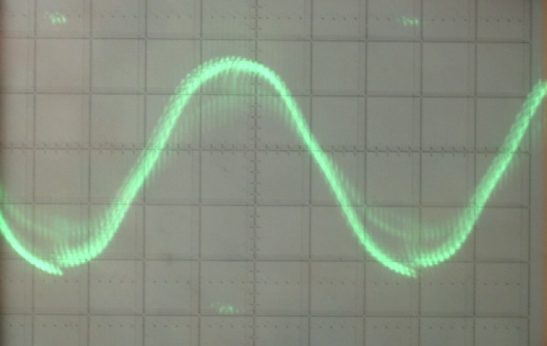
And from all the noise you can extract so much more of information:
This is all done with the P1, and using the P1's ADC
P1 ADC ?
I might have missed that one
Or maybe I am not reading this right and you are referring to the external ADC on some P1 based board ?
I worked for this for some years and some years ago. All the research was done using a P1 and a resistor and a capacitor at an input pin :-) For about 90% of all BLDC's all information in in the signal they call "BEMF". Just connect three resistors to form a virtuel star-point, level shift the signal to an appropriate value using a potentiometer, thats it.
Hi
This is incredibly interesting to me- but the 'secrets' to driving BLDC motor seem to be cloaked in difficult to penetrate language and concepts.
I found the attached application note from microchip fascinating and would like your opinion.
Since high current bldc motor speed controllers are available cheaply for radio control models, it must be doable for hobbyest dabblers like me...
I am particularly interested in doing it sensorlessly.
Dave
It is scientifically proven, the humble bee can not fly. As she doen't know it, she flyes anyway. What we see in the paper is mostly applicable, it's not completely understood. For example shifts the signal at the virtual star point according to the voltage drop due the resistance of the winding. Running a BLDC is really simple as long as there is a lower bound of speed reached. When it comes to efficiency -chasing the last percent- ist becomes more sophisticated.
Cheap model ESC (electronic speed control) units don't PWM the outputs separately and synchronized with the commutation, the have a free running PWM and just commutate. But for finding "zero-crossing" at the higher speed, thats good enough. Model cars or planes are not used at lower speed ;-)
The point is: at higher speed, the motor is a balistic system, that is: nothing changes quickly and any mistake in control can be accepted for some time, so running a motor really is simple. It's harder to do this at low speed. Imagine the crowd at a traffic light waiting for green: the second to start has to eat the dust of the first. Therefor they run the standing motor from the full battery voltage, driving about 5 times the saturation current and even the hall sensor signals shift by 30°, so the motor stutters. It is possible to start such a motor even under those conditions sensorlessly if you know how. But who cares. ..
By the way: app note like that one are around in masses. For decades you find the same theory and minor improvement, but there is no game changer on the road.
Hi ErNa,
I tried to follow your thoughts. Do I get this right: You suggest to use the three winding currents together with their voltages? So for this you need 3 shunts to measure the currents?
Best regards Christof