

Brushless DC Motor Driver
 cgracey
Posts: 14,323
cgracey
Posts: 14,323
Today, Doug Pientak stopped by and I helped him with some code to drive a brushless DC motor. He had an algorithm he wanted to implement, aside from the regular 3-phase PWM, but I don't remember what it was called. We got it working, anyway. Now, he's going to try it on a hoverboard motor.
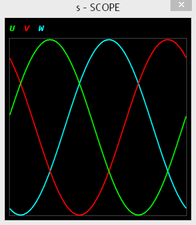
Here is the normal 3-phase output:
Here is the special algorithm added (not skipped over) that is supposed to work better for controlling motors between pole positions:

Here is the code:
' 3-phase motor control code

CON

  _clkfreq = 200_000_000                'set system clock

  BASE     = _clkfreq / 1_000_000       'PWM base time unit
  FRAME    = 1000                       'PWM frame in base time units

  PWM_U_L = 0                           'PWM pins that drive MOSFET drivers
  PWM_U_H = PWM_U_L + 1
  PWM_V_L = PWM_U_H + 1
  PWM_V_H = PWM_V_L + 1
  PWM_W_L = PWM_V_H + 1
  PWM_W_H = PWM_W_L + 1

VAR
  angle, power  '2 contiguous longs

PUB go()

  debug(`scope s)
  debug(`s 'U' 0 `(FRAME) 255)
  debug(`s 'V' 0 `(FRAME) 255)
  debug(`s 'W' 0 `(FRAME) 255)

  coginit(newcog, @driver, @angle)              'launch motor driver

  power := FRAME / 2                            'sequence the angle
  repeat
    angle += $0080_0000
        waitms(1)


DAT             org                             'motor driver that runs in a cog

driver          wrpin   pwmn,#PWM_U_L addpins 5 'set up PWM pins
                wxpin   fram,#PWM_U_L addpins 5
                drvl    ##PWM_U_L addpins 5     'start all PWMs on same clock

.loop           setq    #2-1                    'main loop, get settings
                rdlong  angle_,ptra

                qrotate power_,angle_           'feed three CORDIC operations
                add     angle_,third
                qrotate power_,angle_
                add     angle_,third
                qrotate power_,angle_

                getqy   power_u                 'get three CORDIC results
                getqy   power_v
                getqy   power_w
jmp #.skipmath
                mov     x,power_u               'get smallest power into x
                cmps    x,power_v       wc
        if_nc   mov     x,power_v
                cmps    x,power_w       wc
        if_nc   mov     x,power_w

                mov     y,power_u               'get largest power into y
                cmps    y,power_v       wc
        if_c    mov     y,power_v
                cmps    y,power_w       wc
        if_c    mov     y,power_w

                add     x,y                     'sum smallest and largest, then divide by 2
                sar     x,#1

                sub     power_u,x               'subtract difference from powers
                sub     power_v,x
                sub     power_w,x
.skipmath
                add     power_u,bias            'update PWMs
                wypin   power_u,#PWM_U_L
                wypin   power_u,#PWM_U_H

                add     power_v,bias
                wypin   power_v,#PWM_V_L
                wypin   power_v,#PWM_V_H

                add     power_w,bias
                wypin   power_w,#PWM_W_L
                wypin   power_w,#PWM_W_H

                debug   (`s `sdec_reg_array_(#power_u,#3))

.wait           testp   #PWM_U_L        wc      'wait for next PWM frame
        if_nc   jmp     #.wait

                jmp     #.loop                  'loop


pwmp            long    %000_000000_01_01000_0  'positive PWM output
pwmn            long    %001_000000_01_01000_0  'negative PWM output
fram            long    FRAME << 16 + BASE      'frame and base time
third           long    $FFFFFFFF +/ 3          '120-degree phase step
bias            long    FRAME / 2               'bias to make positive PWM values

x               res     1
y               res     1

power_u         res     1
power_v         res     1
power_w         res     1

angle_          res     1
power_          res     1
Comments
Just heard from Doug. He said he attached a brushless DC motor from a model airplane and it turned super slowly.
Now, he's got it running the hoverboard motor, which was the goal.
Driving 3-phase motors with lightly tweaked waveforms is well-known. There's two possibilities here - The algorithm is trying to correct for torque ripple or, more likely, it's a wye-wound motor and he's letting the center tap float to improve voltage peaks across any given winding given fixed rails. Or both...
He is also going to want some kind of motor feedback - e.g. Hall sensors, an absolute encoder, or undriven phase monitoring to get the phases correct for any given motor speed. Looks like fun!
S.
Yes, he needs to add positional and current feedback, and put it into a control loop.
Look out ST and Trinamic.....Prop2 is gonna eat your lunch")
Nice to have those debug displays to see whats happening
The actual waveform depends on the type of motor... what you have created is more of a trapezoidal wave form that is more tuned to BLDC motors, but a sinewave would be more in tune with a BLAC motor.
Reference:
https://ask.electricaleasy.com/discussion/37/are-bldc-motors-and-blac-pmsm-motors-same
The first you have to know: there is no existing ideal motor. This is just theory. The difference between an AC motor and a DC motor is just: a AC motor runs with alternating current, while a DC motor runs with direct current. Sounds familiar? Is generally not understood!
The point is: every motor creates a torque when there is current. Every motor creates a voltage when it moves. The electrical power fed to a motor (aside of losses) goes to the wheel. If there is no current (no torque) or if there is no rotation (no voltage), then there is no power transfered.
Why does a motor create torque? The answer: because a current flowing through the motor creates a non uniform magnetic field that carries more energy at a given current then a uniform field. So if the motor can move and in doing this, the field becomes more uniform, the energy stored in the field is transfered to the wheel. But when the magnetic field in the motor winding changes, a voltage is created that can be measured at the wires. To keep the current constant the battery has to overcome this voltage and so energy is continuously fed to the motor and transfered to the wheel.
If there is current and a nonuniform field, torque is created and the motor moves, the field becomes uniform and there is no torque even if there is current. For this reason there are different windings or taps at one winding and the current is commutated always this way, that the field stays non uniform. This commutation can be done internaly by the brushed motor or externaly by switching the current to the appropriate wires.
Now: what is the difference between an AC and DC motor? It is NOT the direction of the current flow in the windings, there will always by an alternation. It is the distribution to the windings. A DC motor always runs current into one single winding and this current creates constant torque. That's it. For a BLDC motor there are normaly three windings A-B, B-C, C-A. Those windings are commutated +A>B- -B<C+ +C>A- -A<B+ +B>C- -C<A+ +A>B- etc. 6 steps do one electrical rotation of the motor. There is nothing "trapezoidal" The current is constant (there is a dip to discharge and recharge the inductance, the voltage applied is always constant and proportional to the speed of rotation. It's DC.
In an AC motor the communtation is not "switched", but continously. There is no constant current as the current changes sinoidal and all three phases carry current at every moment. One could think, that an alternating current and voltage leads to torque ripple. But this is not the case at all! The point is that in a 3-phase AC system the energy flows continously like this is the case in DC-system.
As mentioned: the current has to flow in a manner that torque is created. The position of the rotor must be known to drive the current to the coil that creates this non uniform magnetic field. Therefor a sensor device is needed, in the case of a sensorless drive, the motor is the sensor.
The only complication in driving a motor comes from the motor itself, as mentioned: there is no ideal motor.
@ErNa - "There is nothing "trapezoidal" ..."
Not to start anything, but this method has been around for quite some time and is well documented.
Reference:
https://www.ti.com/lit/an/sprabz4/sprabz4.pdf
Hi Beau, just to stop anything: I started many years ago to use the propeller when I had the problem to run a BLDC Motor sensorless. I know exactly what I'm talking about. I can start a motor from unknown position and unknown load savely, I even can create torque when blocked and under saturation, determine the rotors position more precisely then the applied hall sensor, where the switching position varies with torque. To fight against the state of the art in motor control is not different from fighting the start of the art of microprocessors. So the world still belives in motor models that don't even take into account the polarity of the magnets. And the "trapezoidal Control" is nothing but to measure a voltage at a winding that is not linked to the motor driving state. This signal is not available at stand still. So they all twiggle up the motor to about 10% of rotational speed to use this signal to control. 99% of the literature is not worth reading, just an introduction to justify the use of a certain microcontroller and some libraries, written by apprentices.
Just to show the CON (Core of Nonsense): The table on page 3 says: Trapezoidal Bemf versus Sinusoidal Bemf. That is just nonsense and shows a lack in understanding what a "BEMF" is. Electromotoric force has nothing to do with motors, but a lot with motion. EMF is nothing but what we call today "voltage". The term was coined as Galvani discovered that there is a force that can induce the motion of muscles in freshly killed frog legs. At that time, force and energy were not clearly defined.
A BEMF is a voltage that is directed against another voltage. So if you have to coin cells and you connect them back to back (or in parallel, if you like to see it this way) one coin creates an "EMF", the other a "BEMF". As you can see: it's just the point of view to decide, which EMF was first and which is the answer. That is different from when you connect a EMF to an inductance. An open inductance can not carry a current. So the inductance doesn't store energy. The moment you apply an EMF to the inductance, in accordance with Kirchhoffs law, the inductance produces a counter voltage of the same value, that can be seen as a BEMF. But the inductance only can create a BEMF when the current changes, a constant BEMF when the current changes constantly, that is, the current shows linear increase. As the EMF drives a current to the coil, energy is delivered to the coil, so the magnetic field of the coil integrates all the energy, in the end it sums up to 1/2 U I², where U is the value of the EMF (and BEMF) and I is the final current of the current slope. The moment you bring the EMF down to zero, e.g. you short circuit the inductance, the current stays constant as no voltage is applied. Be reminded: there are no losses in a model without losses!
No let us come to the BEMF of a motor. If a motor runs at constant speed delivering a constant torque, the power of the motor is constant. Constant torque means: constant current. Constant power means: current times EMF (BEMF) must be constant. So the BEMF must be constant and there is no place for a trapezoidal BEMF-Shape! The motors BEMF is NOT what you measure at the floating pin of a BLDC, it is the voltage you apply to the winding. And this "BEMF" alway has two components: one from the power to the shaft and one from the motors inductance. This last component stores energy to the coil and that the reason for current ripple when PWM-ing a motor. In the high phase you transfer more energy to the motor, the current rises, in the low phase you transfer less energy than needed, the gap is filled by the inductance, the current decreases. If you apply in average the correct voltage, the current stays constant in everage.
It is such simple. But you can not earn a PhD degree with such a simple item, so it has to be complicated and some exponential functions and imaginary numbers have to be introduced. Complete Nonsense!
Now we can open a discussion and I invite everybody to proof me wrong! (or even prove)
Hi
@ManAtWork
What do you have to say?
Be interested as I know you have experience in these things.
Dave
Erna, I am working with Doug to begin taking feedback from the motor, so that we can more intelligently control it. Is there anything you can do to make me understand this problem better? I will reread what you wrote a few times, hoping I can get to the point where it clicks in my head.
The first time I finally understood a brushless motor was when I took it apart. That led me to draw a real drawing of the windings and magnet positions, and draw a few frames of motion. I had to use an already broken one so i could scrape away the seal on various points of the windings to do measurements.
Do that and you will probably come up with your own "method" to drive it.
If you want to get to the dirty, try adding fast decay into your method.
(driving a forward rotating motor backwards but only for micro pulses) (you better have a really good, protected drive, emf will haunt you)
And also allowing the energy to drain high side or low side..
https://www.precisionmicrodrives.com/content/decay-modes-for-motor-h-bridge-drivers/
Just multiply for all your phases.
But since you have 3, the decay modes get quite.... interesting.
My DC motor runs really crappy at low speeds, I need to give it 50%pwm just to get it to start turning.
So I may benefit from doing fast decay with a 90 pwm at a high frequency to achieve power at low rpm. I am not sure I haven't tried anything other than straight pwm.
The drive(parallax dual MC33926) I use has a INV (invert) pin that might be able to accomplish this but i'd need to look into its response time, but I would need to get into pasm speeds for the program.
And just for fun, get a very fast current sensor on all 6 igbt's.
I would imagine a motor driven very well, that the phase o-scope capture would look like a audio waveform . (peaking quick, dropping quick due to fast decay, etc)
Like holding something from both sides, instead of one side only.
So a motor tug of rope game.
If you are taking control, then hey, your sensors totally matter, you cannot just talk phases, sensors determine the pid algorithm.
Befor we reach the stars we have to dig the ground. Anybody here to explain the Clarke/Park transform in simple words?
Windings of motors with imperfect sinusodial waveforms (that is, all cheap BLDC motors) should always be connected as wye/star. Any clipped or distorted waveform has a 3rd overtone component. That overtone is shorted if you use a delta connection because a 120° phase shift of the base frequency means that the 3rd overtone of all windings are in phase. This causes massive efficiency losses and heating.
And a haven't seen a single BLDC drive with a connected center tap. The "center tap" is used only in very old unipolar stepper motor drives.
Park transformation is explained here: https://forums.parallax.com/discussion/171170/park-transformation-for-motor-control
Another interesting discussion about brushless motors in general: https://forums.parallax.com/discussion/172151/brushless-motors-industrial-servos-encoders-resolvers-etc
Wait couldn't you drive a 3 phase with the dual parallax drive?
I mean only 3A at 28v.... but...
https://www.parallax.com/product/dual-motor-driver-mc33926/
Hi
I'm no expert but I did think to try these H bridge chips for driving a model BLDC motor.
The thing is as I understand it is that you have to be able to 'switch off' one of the half bridges selectively in order to read the back emf for synchronisation and with these bridges you can only do this to the whole bridge, not just a half bridge.
I did try putting a pwm three phase sin wave to the three motor coils at a slowly increasing speed (not detecting the back emf or using hall devices) the rotor would just follow- but it did not work. If I put a slowish speed sin wave in and spun the rotor at exactly the right speed it sometimes would continue, but changing the speed and it would lose synch.
Dave
I have thought on this in the past-- and I have not actually tried this -yet-, But my plan was to have a 'tuning' routine that would spin the motor crudely, then read the winding voltages as it coasted for at least one electrical revolution, and then build my look up table from that..
Comments welcome... I've been stupid before...
What I meant: is anybody else here to explain said transform in simple words?
Can you explain what exactly is the goal a bit more in detail?
a) Running the motor smoothly just for demo (constant speed, without load)
b) driving a constant load (a fan, for example) without direction reversal
c) driving a variable load (for example a vehicle) with direction reversal
a) is very simple. Just apply a waveform that is close to the one you see when spinning the motor with a powerdrill
b) can be done without feedback or with voltage feedback only
c) requires current feedback or position feedback (encoder) or both, especially if you need torque at zero speed
@ErNa
Pain in the a$$ simple enough?")
I have mixed feelings about FOC (vector drives). On the one hand, they opened up a huge opportunity for me but that's another story.
Back in the days of brushed servo-drives, everything was straightforward; a few connections, a pot to scale the velocity, a pot to scale the tach feedback, an offset pot and a current limit....piece of cake.
Along came BLDC where the commutation was handled by hall-effects and setup now involved some form of digital interface; no big deal.
Today, it is no fun to retrofit a modern drive in the field because it wants to know every characteristic of the motor and this often requires hooking up a laptop and figuring out how to use the vendor's setup software. Meanwhile, the motor's rating plate has become impossible to read or it doesn't provide the required information and we're Googling. Then the drive wants to perform an "auto-tune" and for this to work, it states "Motor must be de-coupled from the load"......are you kidding me?
Just give me the hall-effects and a commutation truth table. Who cares about sensorless! Digital should have made life simpler but in this case, it's the opposite.
What do I gain from sensorless or sinusoidal commutation? A motor that runs a bit quieter?
I have, although it was a bit of a 'cobbled together' system using bipolar linear drives on each winding 'tip' and the center tap grounded. A later revision got rid of that. S.
The goal is to run the motor with position feedback. This particular motor has three high/low-output hall effect sensors to detect where you are in the commutation cycle. We are going to use those, since they are simple to read. For output, we generate a 3-phase angle of some power level. The rest is tracking in software.
@Mickster : Progress comes in small steps but integrates to a lot. So modern drives are really needed, no microcontroller without modern drives, no modern drives without microcontrollers, no bread, no butter. Mass production is a case of saving every cent to come down to a $. Here in the forum we often discuss the price level of Parallax products in relation to ebayed products from China. But there is a simple truth: if your product isn't worth the price, try to make it more sophisticated and do not try to save in the supply chain ;-)
But back to motors: I have this serious question: ClarkeTransform is well established in science and technology. So, in my experience, most do not really know what complex numbers are good for. What is the chance to find a "normal" human being being able to follow those equations? 10%? 2%? 80%? I don't know to many in my family.
Clarke transform is an answer to a serious problem. But this answer also is a serious problem. So my question's goal is to find a simple answer to be able to challenge the original problem of motor control.
I'll give one example: to control the current in a coil perfectly, no PID controller is needed. Why? The current in the coil only changes if a voltage is applied at a rate proportional to the voltage. So if the current is not equal to the set value, connect the coil to the highest voltage available, wait some time until the set value is reached and shut off the voltage, that is, short circuit the coil. There is no need for any sophisticated control loop.
Back to the question: who can explain in simple English, what the hack the Clarke/Park transform is good for and what it does in Field oriented Control
>
If you really feel like getting clever, you can combine 'getting started' with the six-step Hall sensors, and then switch to position feedback* drive once you know where your phases are. That way you can have much better phase precision than those Hall sensors. Self-calibrating, too! S.
*Of course, an absolute encoder could do this without Hall sensing - once calibrated.
This is not exactly a rigorous mathematical treatment, but yes, to control the current in a coil perfectly, a PID controller is indeed needed, because nothing's perfect. Your coil has resistance and capacitance. Your shut-off has a finite falling speed. Your magnetic field does not instantly collapse.
What you get is overshoot. Here's a simple-minded metaphor - You climb into your car, you wish to go visit Grandma fifty miles away. You wish to get there in one hour. So you accelerate your car to 50 miles per hour (and you're already late, because that took time) then arrive, at 50mph. Grandma would really prefer it if you slowed down before arriving, because hitting her garage at 50mph is hard on the garage.
ETA: Now, calculate. You know how far away you are (P); include your car's acceleration ability, and deceleration ability (D); and how much time you spend beside the road getting speeding tickets (I) and the PID loop will get you to Grandma's place in a safe and healthy way.
That help any? S.
Everything is relative. Any real inductance has a capacitance, a resistance and an inductivity. If resistance and capacitance do matter, select another coil. Or use the coil as an capacitor or resistor.
To be more precise: If you drive a current of 10 Amps through a Coil of 1 Ohm to create torque, you should not feed that system from a 10V battery.
Ok, I'll give it a try: Park transformation is for brushless FOC what the commutator is for DC motors. It performs a rotation so that you just have to care about one single, stationary DC current instead of multiple sinusodial currents with different rotor angles for each winding.