

Reset circuit woes
 Wuerfel_21
Posts: 5,864
Wuerfel_21
Posts: 5,864
This seemingly simple circuit has been the source of my woes for a long time.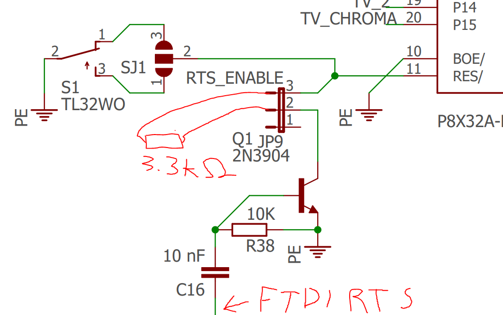
This is the reset conditioning circuit in my Ventilator board. It is literally copied from the one Parallax uses in many designs. Yet it is the number 1 pain point of the design.
Problems I have experienced include:
- Garbled serial (somehow fixed by a 3.3k bodge resistor in series with the jumper, as crudely drawn into the schematic)
- Random resets
- Intermittent download failure
- Resets relating to software activity (mostly to do with SD access) This also depends on the power supply. On my phone charger, it resets just trying to boot Projekt Menetekel, haha.
All of this goes away when I remove the jumper on JP9, so I'm certain that this is the issue. In particular, I think that since I am using a cable that has the FTDI chip in the plug, power/ground noise couples into RTS on the long cable run and is enough to disturb the transistor into conducting enough to trigger a reset.
Or, since the sample size is really just 1, it may not be a design issue. I had weird shorts develop on this board before (due to a combination of crappy soldering skill and low groundplane-to-pad distance). If I measure between the collector and emitter of the transistor (while powered off, of course), I get ~ 30k ohm. Is that a normal value? seems a bit low.
The new prop plug has a slightly different circuit, with a smaller capacitor and a 10K series resistor. Does anyone know the reason for this change? Would replicating this solve the noise issues?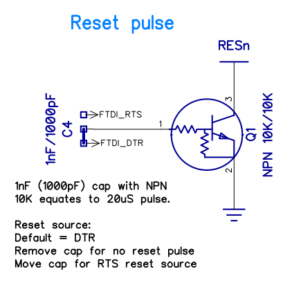
Comments
Hmmm,
If this is the actual circuit, I would consider putting a pull up from RES* to +V just to make sure any noise picked up by the reset pin circuits is not causing random resetting of the chip. I have used various boards, some with the FTDI built in some not. I wanted everything closer to the Prop than I could with fly wires from the GG board to breadboard, so just wired up the Prop ed circuit onto the breadboard. Never had any issues not caused by my own coding errors. Possibly (fill in the blank) may be introducing more noise into the reset circuit when JP9 is present. But I would consider a pull up on the reset pin first. Maybe a 2.2k - 5.6k resistor. A quick scan of Parallax designs seems to show no pull up on Resn, so I wonder if the pin is internally pulled up. But try the pull up to see if it helps. Just my WAG at any rate....
It is internally pulled up with 5K, I don't think that's the problem.
Is this transistor 100% good? Isn't it too good (too high beta?) or doesn't it have too big quiet current? What is the voltage on the collector while normal working?
Voltage on collector measures as 3.30, so all is fine there. However, it does a reset when I touch the voltmeter to the pin, idk what that means.
That's why I asked if it is normal to measure 30k ohm across it, I don't know a lot about transistors.
It's the exact same part parallax uses, 2N3904.
Wasn't sure about internal pull up, learned something new.
What happens if you power it from battery or as isolated a supply as possible? Also, do different plugs act differently? Some "FTDI" like plugs don't quite get it. Acme(actual name starts with Alar..) infusion pump will absolutely not work with any cables but a real FTDI USB to Serial chip in them. Even then my prop plug when plugged into the breadboard will cause my Heathkit power supply to show 1.5V or so on its analog panel meter when supply is off. Noticed that one the other day. Let us know what the cure turns out to be.
I don't have a suitable battery on hand, but I did try multiple USB chargers and my PC and I have a test case that always eventually crashes if JP9 is closed.
I use an actual genuine FTDI own-brand cable (TTL-232R-3V3). (yes, I am aware that these are not technically specced to supply large currents, but the wires are literally thicker than some actual old phone chargers I used to have. I think the specced max current only applies to the variants with 3.3v output. I've powered other things from this exact cable just fine.)
Maybe the noise is actually glitching the FTDI chip though? I should get myself a logic analyzer and find out. Or, I have a P2, has anyone written good logic analyzer code yet?
That reduces the BOM, and has a couple of other advantages
Should be easy to try - replace your 2N3904 with a 10k/10k RET ?
Not my definition of easy. Desoldering is not a thing I'm good at and I certainly don't want to ruin the one (1) functioning Ventilator trying. I also don't have any spare transistors of any kind laying around (If I had, I could try to build the reset circuit on a breadboard and patch it in for testing. Would be even more noisy, but in this case that'd be good thing I think).
But I'll figure something out.
Also thanks for explaining the advantages of the new prop plug circuit. If I don't get a better idea, I'll just put that into the next board revision (that I've been meaning to do forever) and hope for the best. Probably still with discrete transistor/resistor, just because that's more commonly available (do they even make RETs in through hole packages?)
This shouldn't happen if this was a voltmeter and the pin has a proper pullup and /or a decoupling capacitor. It all looks as if there is static electricity and/or electromagnetic noise which induces short peaks of low voltage on RESn. The pullup should prevent the pin from this.
Mind you, this is the ancient half-broken meter I had since I was like 7 or smth. This has been through so much Smile, so maybe it doesn't quite isolate anymore, IDK (This is one of those jankmeters where the current measurement is on the same probe pin... But the fuses for that have been blown years ago...) . Holding the red probe on RESn and repeatedly touching the black probe to ground resets every time. Regardless of JP9 state.
I have a 10K pull-up on RES on all my pcbs. I use a biased transistor ie inbuilt series and base resistor to minimise parts count typically with 1K/10K and the 10nF cap.
You’re probably using PropTool or similar. Don’t forget the reset pulse occurs on DTR (RTS in your case) going inactive, not going active.
Since you’re having problems when using the SD, do you have bulk and bypass caps right at the socket pins? If not you will have problems.
Also, I just verified my theory of the problems coming in through the FTDI cable.
I used some wires inbetween the FTDI connector and its pin header to only connect 5V and GND. No crashes regardless of JP9 setting, even with the phone charger that crashed when booting PM before.
I tried some different combinations aaaand....
The crashes only happen if both RX and RTS are connected. RTS is obvious, no input no reset.
but there's something really weird happening, that being that as long as the FTDI is connected with the extra wires inbetween, ANY serial transmission will cause a reset, even with a terminal open to take the data (so it really isn't hard flow control, which I triple checked is disabled, btw). I double checked this. FTDI connected straight to board: crashes in certain situations. FTDI connected but with wires: instant crash on any RX activity. But not if RTS or JP9 is disconnected. So I think we can really rule out an actual digital issue at this point. And yes, I checked, RX and RTS aren't shorted or anything like that. With the FTDI connected, there's some resistance reading between them, but not consistent between ranges, so not an actual resistance. None of that when measuring either end disconnected. TX to RX measures similiar though, so I guess its normal?
I also tried NOPing out an instruction in the serial transmit routine in PM, such that it doesn't actually toggle RX but retains the same timing. And oh, no crashes.
So the problem is narrowed down.
So I'm left with two theories, both of which suck:
It is midnight now, I'll test more tomorrow.
Sounds like someone needs a new meter; may be adding symptoms into the problem rather than eliminating them. Wal-warts are like that Forrest Gump quote as in you never know what kind of cr@p is inside of it. Should at least use one of the newer ones that can put out over an amp or better (or is known to reliably power a raspberry pi). Even then, some of those have sensing in them for the charging modes for fast charging etc. Nice mess that could make. If you have access to a scope, see what kind of noise is getting through. As to battery, a six volt lantern battery should work, or if you have any sort of electronics house, a 4 slot AA/C/D-cell for about 6V also may work. (If you have any battery toys or stuffed Hallmark $##t that has stopped working maybe salvage the battery tray from that)
Testing semi's was one place the old analog meters were really great. You could do an easy check with them, resistance one way but not the other with C-B and B-E, clearly high to open the other way and high to open CE either direction. DMMs read .3ish to .7ish one way nothing the other C-B and B-E and nothing C-E. I still like the old school way for these. If you are testing it in circuit, watch out for other circuits it feeds that may give you an incorrect reading than when out of the circuit.
As said above, I have since found that it doesn't actually have to do with SD access. I do have a problem where the SD access noise appears on the audio outputs, but that is a separate issue. In my quest to avoid SMD parts, the Ventilator uses a breakout board on some standoffs (also saves board space because the EEPROM and SRAM can live underneath). That board has little SMD ceramics on it. There's also a 22uF electrolytic somewhat near the connector to the breakout, but its a quite busy area so the routing is less than ideal.
6V is no bueno, I actually use the 5V input directly for some stuff. In particular, the keyboard, which I need to do tests without serial connected. Not sure if that likes non-regulated 6V from a battery.
Yeah, will try the scope tomorrow. Although it's analog, so not too useful for this I think.
Certainly, yes. I'm thinking about getting one of those that have a basic scope built-in. No need to lug the analog scope around and digital to boot.
Have you tried a pull-up on reset?
How are you powering you board?
Probably need photos and schematics.
I’ve never used RTS so cannot confirm this. See my schematics for my P8XBlade2 (link in signature). This circuit has no problems. This board runs at 96MHz because I intended to try and run USB emulation within the P1 but never got around to it. My other designs are similar and run at 104MHz.
Personally I would suggest a good DMM, I have an AMPROBE 37XR for home, for work (their cost of course) Fluke 287. You don't likely need fluke but have seen them sorta reasonably at pawn shops (though ebay and other pricing sources kinda screwed the bargains of past times a bit). Got mine at about $100, though best now is $146USD on amazon. Take a scan through EEV blog to see which ones he really slams to avoid. His tests can seem extreme, but if your going probing in a 480 box, ya just may want to know you meter will not be a handful of fire.
As to scopes, I have a couple older Teks, 2247A, 2232 among others, but my main goto unless I need the bandwidth is the Digilent Analog Discovery 2, scope, meter, logic analyzer, +-5Vpower supplies etc. Got mine for around $220 with a bunch of parts and add-ons from a EE student getting rid of one. Been a really useful desktop goto. Others have mentioned some other nice scopes that are pretty reasonable on the budget if you want a scope which is a scope and maybe signal analyzer. They can chime in on that since I don't have one of these...
Regarding batteries, you could always use a 6 battery carrier for 7.5V into a 7805 regulator or if 5.3V is not to unreasonable, you could put one or two 1004 diodes or similar in series with the 6v battery to drop the voltage. Or go expensive and get a converter module for some range in and 5V out. Or if for your bench, low cost supply on eBay. Or modify an older PC poser supply for dedicated 3v3 5 12 Volt outputs. usually only need a green wire jumper to switch supply on and likely a load resistor on one of the HDD connectors so the supply sees a load (many won't work with no load and shutdown)
FWIW I almost always power my boards from the USB PC using the cheapo CP2102 USB-TTL 6pin dongles (ones with DTR).
I'm powering straight from the FTDI cable's 5V pin, which I mostly plug into my PC but sometimes also phone chargers.
I just got out the wires again and did another test.
FTDI connected directly to board: Crash in some situations
FTDI connected through dupont wires: Instant crash on RX activity
FTDI connected through dupont wires, but RX and TX connected together instead of to the board: No crash, even when sending loads of data into the serial port from the PC (and seeing it loop back).
So, I think there's something about how the Prop drives the RX line
It is 2 AM so my judgement may be clouded, but I think I figured it:
FTDI connected through dupont wires, but a 4.7k resistor spliced into RX: No crashes, functional serial.
So it does have to do with driving hard through the long cable. Something something transmission line idk. I guess there's the reason for why the FTDI chips don't drive hard.
4.7k is probably not the ideal value, but that was the first value the part bin spat out, so ehh.
Your 3k3 across the pin hdr is not acting like a pullup. Have you tried a pullup? 10K preferred but since you have a 4k7 try that. It's really too low but should prove the point.
What caps do you have at each Vcc/Gnd P1 pair?
Wuerfel_21,
It's best if you showed the full schematic and are you absolutely sure that your PCB layout matches the schematic?
I have a Velleman DVM850BL which I got in 2004 for $10, but they are now $15 and I don't know if they are built as well as before.
Craftsman 8 Function Multimeter also costs about the same and is not bad for the price, if they are still available.
For testing a transistor, think of it as being two diodes hooked up back to back.
So an NPN would be NP-PN and a PNP would be PN-NP.
A diode should only conduct in on direction, and that's with Positive to P and Negative to N.
Some meters have a diode check function but continuity or resistance should also work.
@Cluso99, I have always powered my stuff from PC if the board has FTDI built in (GG, activity board, C3 etc.) and separately powered when using breadboards,minis etc and PropPlug as it provides no +5V that I know of. May have to try that CP2102 module down the road a bit.
@Wuerfel_21, Seeing your complete schematic is a good idea to get help. Unfortunately for this problem, you will not likely be able to find the schematic for the USB-serial plug. Try power separately and program it with a prop plug. This should separate the issue to either the USB converter side of the interface or the PCB side of the interface. Or power.
Tired, hope this made sense or was useful.
FF
Ok, did some more tests:
FTDI connected through dupont wires, 3.3k series resistor moved to breaboard: Instant crash
As above, but with 9.4k pullup on RESn: No crash??!?!?!?!?!?
I didn't think that'd do anything, but it does. I can even remove the pullup while its running and have it crash soon after. @Cluso99 knows what hes talking about.
So to recap, either a series resistor on RX or a pullup on RESn can solve the issue. Both at once also work.
I still want to have look at this with a scope, but I don't think my analog one is of much use for this.
But here's what I'm going to do. To fix it on my current board, I'll somehow bodge in that RESn pullup. There's a bunch of unused spots on those pullup networks, just going to wire to that.
On the next board revision (the main block for which beside my own laziness was these reset issues), I'll add the improved transistor circuit, a 10k RESn pullup and 3.3k series resistors on RX and TX (which as a bonus would allow using a serial adapter with 5V IO levels)
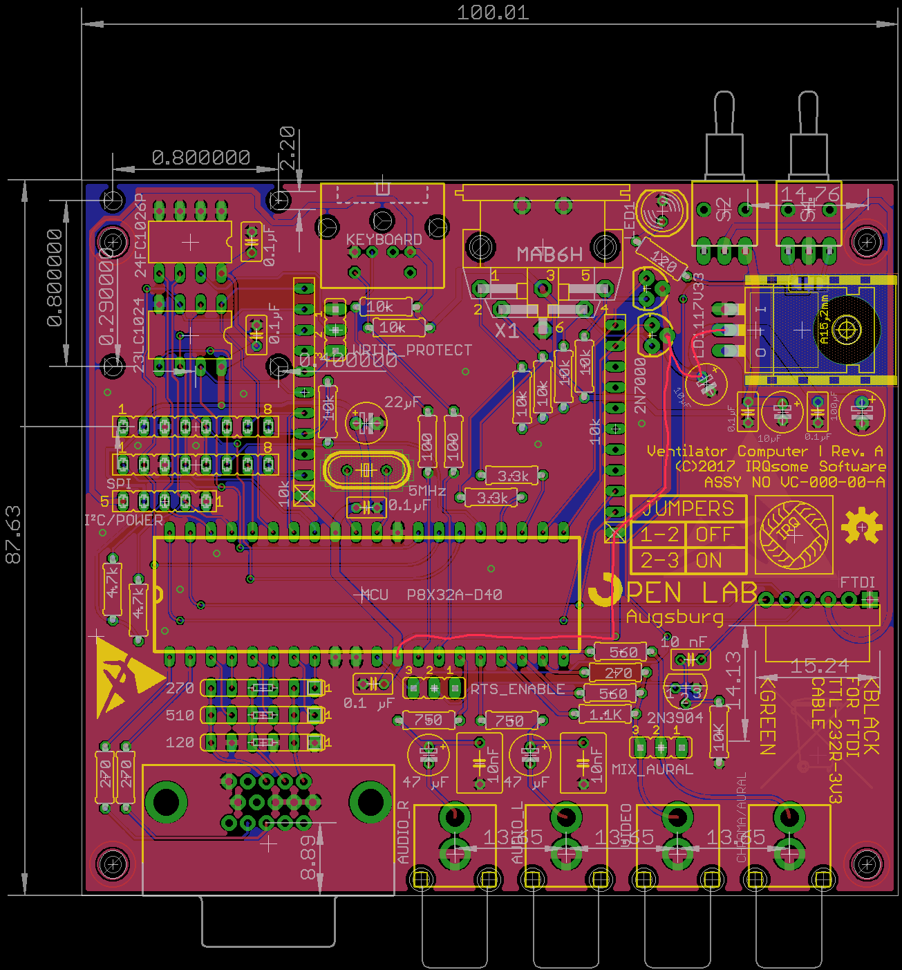
I've also attached the full schematic and layout for the curious.
Correction to the above: The RESn pullup does not actually solve the problem. Together with the 3.3k series resistor on JP9 it just pulls too hard for the serial reset to happen at all. If I remove the series resistor on JP9 the problems come back. So the only actual solution seems to be the RX inline resistor.
The 3k3 on jp9 should not be there as you’re limiting the reset signal.
If you think about the reset pin in the P1, it has a high value pull-up and an effective cap to GND. When power is applied, the resistor let’s the cap charge up, delaying the reset pin going high and removing the reset.
By placing the 3k3 into the collector, you are creating a voltage divider when the transistor operates. This will limit low, and hence how long, the reset will be pulled below the threshold. While this isn’t your problem, you need to fix it as you’re causing other issues.
Without checking above, I note on your pcb you have a 22uF bulk cap on the 3V3 rail near the xtal. IIRC it’s an electrolytic. It should be tantalum if it’s thru hole. You really should have another on the other side of the P1 across the 100nF. Of course I’m presuming there are tracks not shown on the underside, and I am presuming your 3v3 rail goes to the 22uF and the to the P1 pins ie not to the P1 which has a track then going from P1 to the 22uF.
Your explanation of your problem is an indication of the power rail suffering brownout.
Oh, it is like that, the power goes to the P1 pins first and then to the caps. Does that really matter?
I've drawn in how the power comes in from the regulator here:
I don't think the problem is with the power supply though. How would putting that RX series resistor make any difference to that?
(although, as said above, I would like it if I didn't get SD card noises on my audio pins, so I think I'll improve the power distribution a bit for the revision, anyways)
Does that actually matter? I've not seen tantalums used anywhere else. And don't they, like, explode when you look at them wrong?
Yes, the placement of caps does matter. The bypass goes closest to the pins followed as close as possible by the bulk cap, and that then goes to the regulator, and the reg should also have bypass and bulk caps on the output right at the reg pins. Often the reg specs omit advice about bypass as its often assumed. You will need input bulk cap(s).
Don’t fall for the bigger caps are better. This hasn’t been the case since the advent of modern regulators. If your cap is too big on the output you can cause problems with the reg trying to supply the inrush current to the cap on power up, causing all sorts of problems including failure. If you’re powering from the 5V USB an input of 22uF should be max although IIRC the actual spec says a limit of 10uF. Note I have 2 x22uF on my P2 RetroBlade inputs and power this from PC USB without problems.
A tantalum provides quicker response time to transient current requirements. Monos can be used nowadays but they are usually smt. Your cap types are important. Use X7R or X5R monos 10% max. Don’t use Z5U or Yxx. Tantalum should be rated at least twice voltage for safety. Don’t put them backwards. BTW electros also explode too and they are messy. But it’s almost always a power problem that causes problems. I’ve never had a tantalum fail, and only once with electros - big ones in the x000uF in a 400V inverter I built for a valve transmitter final.
Can you draw you power setup? Start left to right from the USB input.
You have a 100nf on P1 pin 12. This is where you will need to add a 10-22uF cap across the 100nf. If you don’t have a tantalum then use an electro for now. As I said, not the best but hopefully should work. I cannot really work out what is going on at the regulator, nor what is happening after the P1 power.
You’re saying a series resistor in rx stops the unwanted resets. Are you meaning the P1 receive on P63? You don’t need one in the other leg as the P1 only outputs 3v3 and that is fine into the FTDI chip.
Can you post a pic of your setup because your problem really doesn’t make a lot of sense?
Yes, if you really do want to use long cables, you will need to take care about crosstalk.
The reset transistor is a sensitive node, needing just over 500mV to trigger, and direct into the transistor base.
A fast edge from an adjacent long wire, is likely to cause problems.
If you have found a solution, try lowering the resistor until it fails to check you have enough margin.
Also check on a scope to make sure the baud rate you want to use, is ok with that series R.
It looks like you can add a 10k series R to the Reset TRX base on that layout, which would let you prove the revised reset circuit.
Sounds good, check with a scope on the RESn waveform/width and on the RX and TX levels/edges, when used with your long cable.