Yes, I want to watch the demo too.
But I'm still missing the DVI adapter.
I still have to build it.
You can fool the eye, but the ear doesn't miss a thing.
I have installed 5 oscillators so far.
Two of them have an extra reel. (LFO)
The 1st generates an amplitude modulation at 3..5.
The 2nd generates a frequency modulation at 3..5.
If everything works out, I will be able to add 5 more.
And all this in one COG.
Then there will be 5 of them working around in the propeller. 50 oscillators - a great idea
Translated with www.DeepL.com/Translator (free version)
The NOP is not needed for what's there. So something else, not listed, is the problem.
fr2 is an IEEE float. It won't be usable without conversion using constant ROUND(), ie: At compile time only. It is not run-time usable unless you know how to decode a float, bit by bit.
I have now replaced the wait function "waitse1" with "waitct1".
I let the DAC run freely with 1M/s sampels.
By "waitse1" I can reduce the sampelrate to 250k/s and get the needed computing time.
I don't need the NOP anymore.
I have made the calculation over constants, here rounding errors can be removed more easily.
Signal image of 20kHz at 250k sampling rate.
With the help of linear interpolation, I want to calculate the 3 missing intermediate values.
So I come to 1M sampling, and the stairs become smaller.
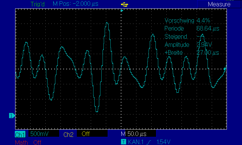
Here is the sum signal of 4 oscillators.
Now come square, triangle and PWM.
And everything must be based with the same values as the sinius.
dacs is now fixed at 256.
Otherwise it makes no sense in the project.
I still have to come up with something for the other signal types. Tables are unsuitable here.
I'm racking my brains over the interpolation. But I haven't found a useful solution yet.
I will probably reduce to 200ks.
That will make the calculation easier, divide by 2, 4 and simple addition.
Cordic can go a lot faster for prebuilding multiple points. Just have to stagger the calculations to use the pipeline. Up to one command per 8-clocks. And if that is still not enough, the next level is get other cogs to help by using their share of the Cordic. It can, in theory, achieve a command per clock.
Note how results have to be collected too. Two GETQ's, an ADD, and QVECTOR is 8 sysclocks, so couldn't issue commands faster even if the pipeline could go faster.
I just took your prior listing and optimised around the cordic's QDIV. Making it 14 clocks faster by not having to twiddle thumbs for so long. Nothing else.
Yes, the QDIV to GETQX is stall time, like a NOP, until result comes available.
@pic18f2550 said:
OK, now I've eaten it.
The cordic is like a coprocessor for the COG.
Therefore, it can perform calculations in parallel with the COG.
Yes.
Does each COG have its own cordic?
Not quite. It's one fully pipelined unit with 54 stages. By "fully" I mean it can be issued a new command on every clock cycle. Which means there is 54 individual stages of hardware in that unit, many of them are identical functions, that constitute the whole Cordic operation.
It is located in the Hub. Each Cog gets one-in-eight slots of the command issuing. Which has the effect of it being in all eight Cogs. This allows excellent performance in a compact footprint and still fits the deterministic symmetry of the Propeller.


Comments
I multiplied freql, not clkfreq. But dividing clkfreq is also an option.
I already have tomatoes on my eyes.
Here, 268,437,500Hz would be a bigger calculation error than 256,000,000Hz.
Thank you
The assembly code below is the same as
f1 long round(freql * 65536.0 * 65536.0 * 256.0 / float(clkfreq_))The calculation of the sine curve is all well and good, but it consumes more than 60 clk impulses.
I will rather create a sin table in the hram.
That is definitely faster.
That way I can calculate the frequency more easily. The missing gaps are simply calculated out.
No problem. Good exercise anyway. Chip's Spiral Demo is a good one to have a look at for seeing the Cordic in heavy use.
Yes, I want to watch the demo too.
But I'm still missing the DVI adapter.
I still have to build it.
You can fool the eye, but the ear doesn't miss a thing.
I have installed 5 oscillators so far.
Two of them have an extra reel. (LFO)
The 1st generates an amplitude modulation at 3..5.
The 2nd generates a frequency modulation at 3..5.
If everything works out, I will be able to add 5 more.
") 50 oscillators - a great idea
50 oscillators - a great idea ")
And all this in one COG.
Then there will be 5 of them working around in the propeller.
Translated with www.DeepL.com/Translator (free version)
VGA version - https://forums.parallax.com/discussion/comment/1484706/#Comment_1484706
In my attempts, I have come across something that I can't explain.
A wrong frequency is generated here.
dac2
        {{ 1. Sampelausschnitt und Amplitute Berechnen }}
        add     ph1, fr1
        qrotate am1, ph1
        getqy   outw
        bitnot  outw, #15
The correct frequency is generated here.
dac2
        {{ 1. Sampelausschnitt und Amplitute Berechnen }}
        add     ph1, fr1
        nop                 '<--- Warum auch immer sonst stimmt getqy nicht
        qrotate am1, ph1
        getqy   outw
        bitnot  outw, #15
fr1 and fr2 are apparently not the same either.
Since a frequency error also occurs here.
The NOP is not needed for what's there. So something else, not listed, is the problem.
fr2 is an IEEE float. It won't be usable without conversion using constant ROUND(), ie: At compile time only. It is not run-time usable unless you know how to decode a float, bit by bit.
I have now replaced the wait function "waitse1" with "waitct1".
I let the DAC run freely with 1M/s sampels.
By "waitse1" I can reduce the sampelrate to 250k/s and get the needed computing time.
I don't need the NOP anymore.
I have made the calculation over constants, here rounding errors can be removed more easily.
Cleaned up the constant floats for you (without a "." they are integers):
Best not to use ASMCLK when mixed Spin/Pasm. It's for pure pasm only code. Just let Spin handle the sysclock setup.
The "dacs" value isn't suitable for PWM dither either. I'd ditch the variable and just use an immediate
WXPIN #256,#pin1EDIT: The small value in "dacs" will be why the WAITSE1 wasn't good.
Pin mode value commented:
asmclk I have taken out, had no negative effects,")
With the help of linear interpolation, I want to calculate the 3 missing intermediate values.
So I come to 1M sampling, and the stairs become smaller.
Here is the sum signal of 4 oscillators.
Now come square, triangle and PWM.
And everything must be based with the same values as the sinius.
Nice.
But "dacs" needs to be a multiple of 256 if you want the PWM dither to work. And then you can correctly go back to using WAITSE1.
dacs is now fixed at 256.
Otherwise it makes no sense in the project.
I still have to come up with something for the other signal types. Tables are unsuitable here.
I'm racking my brains over the interpolation. But I haven't found a useful solution yet.
I will probably reduce to 200ks.
That will make the calculation easier, divide by 2, 4 and simple addition.
Cordic can go a lot faster for prebuilding multiple points. Just have to stagger the calculations to use the pipeline. Up to one command per 8-clocks. And if that is still not enough, the next level is get other cogs to help by using their share of the Cordic. It can, in theory, achieve a command per clock.
Let's see if that works too.
{{ linear interpolation }} mov outwd, outwa {{ 2 }} sub outwd, outwn {{ 2 }} qdiv outwd, #3 {{ 9 }} getqx outwd mov outw1, outwa {{ 2 }} bitnot outw1, #15 mov outw2, outwa {{ 2 }} add outw2, outwd {{ 2 }} bitnot outw2, #15 mov outw3, outwa {{ 2 }} add outw3, outwd {{ 2 }} add outw3, outwd {{ 2 }} bitnot outw3, #15 mov outw4, outwa {{ 2 }} add outw3, outwd {{ 2 }} add outw3, outwd {{ 2 }} add outw3, outwd {{ 2 }} bitnot outw4, #15 mov outwa, outwn {{ 2 }}Here's a part of Chip's Spiral Demo. It demonstrates how to fill the Cordic pipeline:
.pixels qvector .x,.y '0 in 'do overlapped QVECTOR ops for 16 pixels add .x,#1 '1 in qvector .x,.y add .x,#1 '2 in qvector .x,.y add .x,#1 '3 in qvector .x,.y add .x,#1 '4 in qvector .x,.y add .x,#1 '5 in qvector .x,.y add .x,#1 '6 in qvector .x,.y add .x,#1 '7 in qvector .x,.y getqx .px+0 '0 out getqy .py+0 add .x,#1 '8 in qvector .x,.y getqx .px+1 '1 out getqy .py+1 add .x,#1 '9 in qvector .x,.y getqx .px+2 '2 out getqy .py+2 ... ...Note how results have to be collected too. Two GETQ's, an ADD, and QVECTOR is 8 sysclocks, so couldn't issue commands faster even if the pipeline could go faster.
If everything works out, I'll be there with 35 sysclocks.
The "bitnot" already belong to the signal conversion of the PWM.
I've shaved 14 clocks from your above code:
{{ linear interpolation }} mov outwd, outwa {{ 2 }} sub outwd, outwn {{ 2 }} qdiv outwd, #3 {{ 9 }} mov outw1, outwa {{ 2 }} bitnot outw1, #15 mov outw2, outwa {{ 2 }} mov outw3, outwa {{ 2 }} mov outw4, outwa {{ 2 }} bitnot outw4, #15 mov outwa, outwn {{ 2 }} getqx outwd add outw2, outwd {{ 2 }} bitnot outw2, #15 add outw3, outwd {{ 2 }} add outw3, outwd {{ 2 }} bitnot outw3, #15 add outw3, outwd {{ 2 }} add outw3, outwd {{ 2 }} add outw3, outwd {{ 2 }}How do you come to 14?
        {{ linear interpolation }}
        mov     outwd, outwa     {{  2  }}
        sub     outwd, outwn     {{  2  }}

        mov     outw1, outwa     {{  2  }}
        mov     outw2, outwa     {{  2  }}
        mov     outw3, outwa     {{  2  }}
        mov     outw4, outwa     {{  2  }}

        shr     outwd, #1        {{  2  }}{{ DIV outwd/2 }}
        add     outw3, outwd     {{  2  }}
        add     outw4, outwd     {{  2  }}
        shr     outwd, #1        {{  2  }}{{ DIV outwd/2 }}
        add     outw2, outwd     {{  2  }}
        add     outw4, outwd     {{  2  }}

        mov     outwa, outwn     {{  2  }}
{{ clock cycles from Propeller 2 Rev B/C PASM Instructions }}
Seven instructions between QDIV and GETQX.
I just took your prior listing and optimised around the cordic's QDIV. Making it 14 clocks faster by not having to twiddle thumbs for so long. Nothing else.
OK, now I've eaten it.
The cordic is like a coprocessor for the COG.
Therefore, it can perform calculations in parallel with the COG.
Does each COG have its own cordic?
{{ ==== 1. linear interpolation }}
        mov     outw1, outwa     {{  2  }}
        mov     outw2, outwa     {{  2  }}
        mov     outw3, outwa     {{  2  }}
        mov     outw4, outwa     {{  2  }}

        mov     outwd, outwa     {{  2  }}
        sub     outwd, outwn     {{  2  }}
        qdiv    outwd, #2        {{  2 (9)  }}
        NOP                      {{  OP-CODE SPACE 2 }}
        NOP                      {{  OP-CODE SPACE 2 }}
        NOP                      {{  OP-CODE SPACE 2 }}
        NOP                      {{  OP-CODE SPACE 2 }}
        NOP                      {{  OP-CODE SPACE 2 }}
        getqx   t1               {{  58 }}
        add     outw3, t1        {{  2  }}
        add     outw4, t1        {{  2  }}
        qdiv    outwd, #4        {{  2 (9)  }}
        NOP                      {{  OP-CODE SPACE 2 }}
        NOP                      {{  OP-CODE SPACE 2 }}
        NOP                      {{  OP-CODE SPACE 2 }}
        NOP                      {{  OP-CODE SPACE 2 }}
        NOP                      {{  OP-CODE SPACE 2 }}
        getqx   t1               {{  58 }}
        add     outw2, t1        {{  2  }}
        add     outw4, t1        {{  2  }}

        mov     outwa, outwn     {{  2  }}
For better understanding, I have not optimized the code.
Yes, the QDIV to GETQX is stall time, like a NOP, until result comes available.
Yes.
Not quite. It's one fully pipelined unit with 54 stages. By "fully" I mean it can be issued a new command on every clock cycle. Which means there is 54 individual stages of hardware in that unit, many of them are identical functions, that constitute the whole Cordic operation.
It is located in the Hub. Each Cog gets one-in-eight slots of the command issuing. Which has the effect of it being in all eight Cogs. This allows excellent performance in a compact footprint and still fits the deterministic symmetry of the Propeller.