

Measuring Skateboard Tilt
 Duane Degn
Posts: 10,588
Duane Degn
Posts: 10,588
in Robotics
I'm building my own electric skateboard from parts.
I'd like to add an electronic differential to the contraption. As described in this Youtube video, an electronic differential will adjust the motor speeds to aid in turning.
I haven't figured out how Bajaboard senses the tilt of the board. It might be an IMU. An IMU might work well but it seems to me there are several situations where an IMU could be confused. I doubt an IMU would be able to distinguish between tilting the board and riding on a slope.
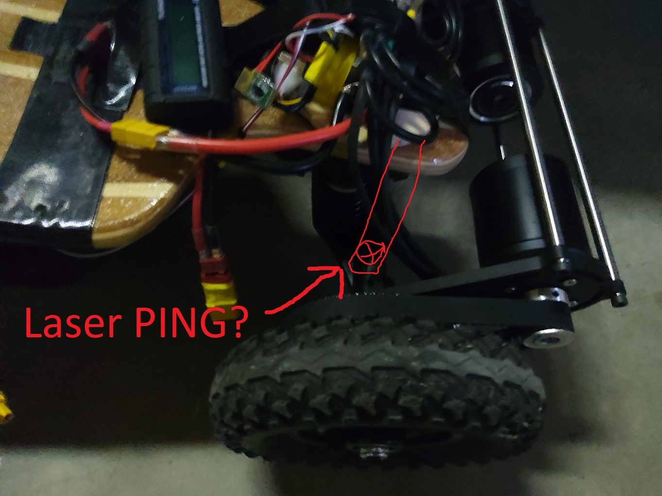
I might try the IMU approach but I first thought I'd try measuring the distance from the truck to the board. I'd mount a LaserPING pointing down at the truck. Hopefully this will allow me to measure tilt by sensing the distance between the sensor and the truck.
Here's a sketch attempting to show my idea.
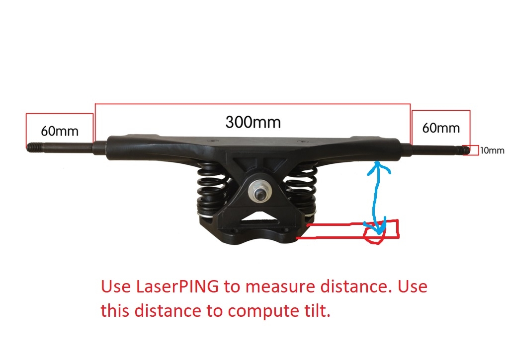
A different angle with only the truck shown.
I'm using a dual VESC to control the motors. This should allow me to use a Propeller to set the speed of the individual wheels.
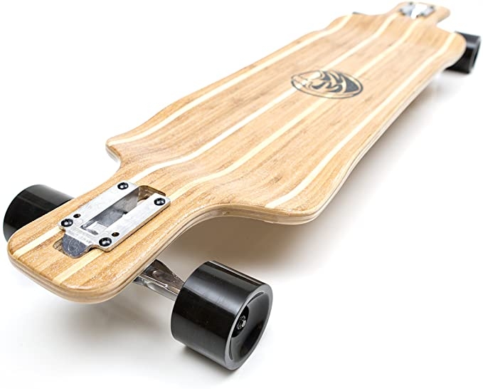
I'm adding the ESCs and motors to a longboard purchased off Amazon.
Do any of you see any obvious problems with this plan (besides the horrific bodily injuries it's likely to cause)?
Do any of you have suggestions on alternative ways to sense the tilt of the skateboard?
I'd like to add an electronic differential to the contraption. As described in this Youtube video, an electronic differential will adjust the motor speeds to aid in turning.
I haven't figured out how Bajaboard senses the tilt of the board. It might be an IMU. An IMU might work well but it seems to me there are several situations where an IMU could be confused. I doubt an IMU would be able to distinguish between tilting the board and riding on a slope.
I might try the IMU approach but I first thought I'd try measuring the distance from the truck to the board. I'd mount a LaserPING pointing down at the truck. Hopefully this will allow me to measure tilt by sensing the distance between the sensor and the truck.
Here's a sketch attempting to show my idea.
A different angle with only the truck shown.
I'm using a dual VESC to control the motors. This should allow me to use a Propeller to set the speed of the individual wheels.
I'm adding the ESCs and motors to a longboard purchased off Amazon.
Do any of you see any obvious problems with this plan (besides the horrific bodily injuries it's likely to cause)?
Do any of you have suggestions on alternative ways to sense the tilt of the skateboard?
Comments
You must have skills I don't, to consider your alternative less hassle.
I haven't seen transverse leaf springs used on skateboards though I admit I'm pretty new to this sort of thing.
Edit: if re-engineering the suspension isnt in the cards, a couple of string pots between the board and the trucks would give you the same data. Example: https://unimeasure.com
https://forums.parallax.com/discussion/167675/repurposing-a-broken-servo360
Secure the body to the underside of the board and the shaft to the axle, such that the shaft and axle tilt axes are collinear.
-Phil
Those are cool string pots but the Unimeasure ones are pretty expensive. I suppose I could do something similar with a ten turn pot and some string. I'm not sure I'll use it but thanks for the idea.
I actually have a bunch of Hall effect encoders.
I could rig up some sort of mount like you suggest. I now have a 3D printer to aid in building these sorts of contraptions.
I'll see what sort of resolution I get from the LaserPING but then try one of the other ideas presented here if I don't like how the LaserPING works. The LaserPING just seems like it will be really easy to mount.
As I think about how I want the final vehicle to look, I may want to use the encoder idea (it should look sleeker).
I have a second set to motors and ESCs. I plan to make this a 4 wheel drive vehicle. I need all four wheels to be powered when I eventually make Mecanum skateboard wheels.
I've heard of people being seriously hurt on electric skateboards but I've never heard of anyone being hurt riding a Mecanum wheeled electric skateboard. This must mean Mecanum wheeled electric skateboards are very safe. What could possibly go wrong?
This is some grand mischief and I look forward to seeing the result.
Mike
I noticed you show the as5355 product in one of your photos. hos much more accurate do you want? print an enclosure and your off.
Jim
I'd need to rig up some way to hold the encoder PCB at the pivot point and the magnet at the pivot point without attaching either to the bolt.
Supposedly this is an off road skateboard. I'm not crazy enough to try riding this off road, but someone might want to try riding the board off road. It would be nice if the tilt sensor weren't vulnerable to rocks and logs.
I need to figure out how to get a Propeller to talk to the VESC before I do much of anything else.
Mount a rotary encoder (Servo360?) on top of the board with the shaft along the midline of the board and the midpoint of a string secured at top dead centre of travel.
The ends of the string can be secured in loops around the truck on each side, so that as the truck tilts, the encoder turns with it. When the suspension has to accommodate a bump the string may go slack momentarily, so you may need to account for that in the code, but if the string can never be pulled so tight that it stresses the bearing of the encoder it should be mechanically sound.
This keeps the electronics out of the way of rocks and logs, and a suitable enclosure protects them from feet.
Adding an accelerometer into the design could help detect those times where you've hit a bump.
Thanks for all the good ideas.
While the trucks kind of look like they have shocks, these only resist the pivoting of the trucks. The distance between the pivot and the top of the truck is constant. Here's a photo the top of the truck.
There will likely be some rubber between the top of the truck and bottom of the board so the encoder should probably be mounted to the top section of the truck with with the string or equivalent passing down to the lower section of the truck. There's an opening in the top of the the trucks and openings in the board directly above the trucks. These opening could be use to route wires from the encoder.
As mentioned earlier, I have several AMS5055 encoders with appropriate magnets. I'll likely try to use one or two of these to measure the pivot.
I think your idea of using an encoder pivot point parallel (and above) the actual pivot, will make mounting the encoder easier than attempting to mount the encoder in line with the pivot point.
While I don't think bumps are going to cause the trouble you original where concerned about, I intend to load the board with all sorts of sensors. This will hopefully end up being able to autonomous at times. I don't plan to have a self driving skateboard (though that does sound cool). I think I'll keep humans off the board will under autonomous control.
Duane,
A IMU chip would gives you Euler roll angle, which indicates tilting.
You are correct in pointing out the fact that riding on a slope will be seen as tilting, but would that not be the same with any sensor because on a slope you have to tilt to stay upright?
The only foolproof way I can think of is two distance sensors, one on each edge of the board which measure the distance to the ground.
I understand these boards have small wheels, so they will not really be ridden over uneven ground.
Thanks for the fun ideas. While fun, they don't sound very easy to implement. I do like the idea of being able to tune the roll stiffness. These sorts of trucks are supposed to be mounted at around 30 degree away from the center of the board. Normally off road skateboards have angled nose and tail sections so the truck can be mounted directly to the board. Since I'm using a normal board, I need to add wedges to angle the trucks.
The first set of wedges I added were much too small to produce the required 30 degree offset. The 13 degree wedges I used made the board very difficult to turn. This angle also make it hard just to balance on the board since the springs seemed so weak. It would have been nice to be able to stiffen the roll in this case.
I'm headed to the hardware store to get longer bolts so I can use larger wedges.
Again thanks for the fun ideas.
I think the Baha Board uses an IMU. I'll include an IMU in my contraption and see how well it works at determining the tilt. I wanted to try several different approaches. This thing will likely a robotics project as much as it is an electric skateboard project.
The wheels which came with the motors and trucks are 8" (about 200mm). There's pneumatic (there are inner tubes in each tire) and should be able to handle rough terrain. While the wheels and truck can handle rough terrain, I'm too much of a chicken to go off roading with this thing myself.
I've ordered a bunch of the laser sensors used in the LaserPING. I'm hoping the I2C interface will allow faster updates than the Parallax version (which is still faster than an ultrasound PING). I'll likely point a few of the I2C sensors at the ground and compare the data with sensors pointed at the truck axles.
While I'll likely try to measure the distance to the ground from the board, I' think monitoring the distance between the board and one of the axles would produce a more reliable reading of how much the board is tilted.
As I mentioned elsewhere in this thread, I'll likely use this contraption as excuse to try out all sorts of sensors.
Thanks for the suggestions.
Mike
I think you're right.
An IMU would likely do the job. I think there's something wrong with me. I don't think I'll be able to stop myself from adding additional sensor even if they're not needed. My brain seems to think there's no such thing as too many sensors.
It could be fun to compare the various sensor data. I'll likely add a SD card or flash chip to log the data.
In case anyone is interested, these sorts of off road wheels and motors are usually used on boards which have their nose and tail angled up by 35 degrees. Here are a few images showing appropriate boards for this hardware.
I assure you all, I spent much much less than the $3,600 price of board in the last two images. Those boards cost more than several cars I've owned.
My gut says you guys are right but my gut doesn't have a good track record of being correct.
As a way of an update on this project here's a photo of a couple 35 degree wedges (the two on the right are 35 degrees the one on the left is rubber and about 14 degrees). I'll likely not use these wedges.
The holes in either the board or the truck would need to be enlarged to ovals in order for the bolt to pass through everything. Neither the board nor the truck would likely survive being modified so drastically so I'm looking for a reasonably priced mountain board deck.
BTW, It sure is fun being able to print a part with a 3D printer. I've had my 3D printer a few months and I have a hard time understanding how I managed life without it.
With two wedges (fore axle/aft axle) and 3 strains per wedge you could then calculate rider weight in addition to the roll angle. This means you could integrate it into the motor speed control loop such that moving your weight forward makes it accelerate, while moving body weight backwards slows it down. And if you fall/jump off, the board stops.
Just thinking out loud here.
That sounds like a really interesting idea.
I'm going to need to redesign my wedge. Before I print it, I'll post from CAD images here and maybe you could suggest where to place the strain gauges?
I actually purchased a bunch of strain gauge amplifiers a few months ago. I never figured out which sensors I should purchase.
These are the amplifiers I purchased.
These were listed as: "HX 711 Module Weighing Sensor Pressure Sensor 24 Bit AD Module"
Would something like this be appropriate for the skateboard application? Do you know of a better alternative for this application?
I have used the Sparkfun version of that board. They work nicely. No issues there.
Posting pictures from phone. Will edit post with explanation momentarily
OK. I suck at drawing.
After thinking about it, I think you only want two strain gauges per axle. The idea is to make these gauges individually sensitive to roll, and collectively sensitive to total weight.
The pictures give a (terrible) example of what I think would do that.
Blue is the existing hardware (wheels, trucks, pivot, springs, etc).
Green is the spacer you'll be printing anyway.
Red is *another* spacer (a shim), about 1/4 inch thick, that you can print that contains the strain gauges (shown in black).
The key bit is the two "buttons" (green spheres) that you would engineer into your wedge spacer. These create points of concentrated force during roll that press on the strain gauges in the red shim. The shim will need to be made to deform slightly, likely by mounting it by the edges and slightly spacing it away from the board (washers? 3d printed ledge? You decide. )
You'll need to engineer some sort of floating pin-line system that will not allow the spacer/wedge/board to separate, but will allow roll inputs to flow without resistance.
So your roll input is (Strain A - Strain
Anyway... that's all I got. Hopefully the concept is clear even if my art abilities suck.
EDIT2: You could make it so the "shim" could be quickly removed. That way you can actually ride the board between dev cycles without messing with cables and other Smile. Just bolt your wedge to the board as normal, sans shim.
On the other end of the fun scale, rust in the gas tank:
-Phil
-Phil
A: Never!