

Reciprocal Counter Demo
 cgracey
Posts: 14,323
cgracey
Posts: 14,323
There have been some questions about the reciprocal counter modes. A few of you have also been asking about how to do simple I/O, like serial with decimal number printing, so that you can see what's going on inside. It's all in here. This reciprocal counter is Jmg's baby, by the way. He really wanted this in the chip and it's pretty neat how it works.
This demo shows the reciprocal counter modes working together to form a pretty competent frequency counter. It outputs serial text at 1Mbaud and works really well with the Parallax Serial Terminal:
It's set up for 250MHz and the minimum sample time (msr_us) can be set from 1us to 5 seconds. It also demonstrates some practical math and number printing.
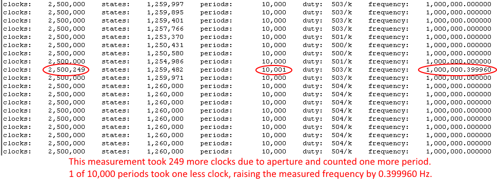
Here is a screenshot of some serial output, while the minimum sample time is 10ms and it's receiving a 1MHz square wave into P0:
This demo shows the reciprocal counter modes working together to form a pretty competent frequency counter. It outputs serial text at 1Mbaud and works really well with the Parallax Serial Terminal:
'****************************************
'*  Reciprocal Counter Demonstration    *
'*  - inputs frequency on P0            *
'*  - transmits serial text on P62      *
'****************************************
'
con		sysfreq		= 250_000_000.0		'system frequency
		msr_us		= 10_000.0		'minimum measurement time in microseconds (float)
		msr_pin		= 0			'pin to measure frequency on, uses next two pins
		baud		= 1_000_000.0		'serial baud rate on P62 (float)

		msr_min		= sysfreq/1e6*msr_us	'minimum measurement time in system clocks
		msr_pins	= 2<<6 + msr_pin	'group of three pins starting at msr_pin

dat		org
'
'
' Setup
'
		hubset	##%1_000001_0000011000_1111_10_00	'enable 20MHz crystal and PLL
		waitx	##20_000_000/100			'wait 10ms for crystal and PLL to stabilize
		hubset	##%1_000001_0000011000_1111_10_11	'switch to PLL

		wrpin	msr_time,#msr_pin+0		'configure smart pin for clocks count
		wrpin	msr_states,#msr_pin+1		'configure smart pin for states count
		wrpin	msr_periods,#msr_pin+2		'configure smart pin for periods count
		wxpin	##round(msr_min),#msr_pins	'set smart pins' x-value to clocks in msr_us
		wypin	#%00,#msr_pins			'set smart pins' y-value to rise-to-rise
		dirh	#msr_pins			'concurrently enable smart pins

		wrpin	#%01_11110_0,#62		'configure async serial output
		wxpin	tx_mode,#62
		dirh	#62
'
'
' Take measurements
'
.loop		akpin	#msr_pins			'clear any old measurement
		waitx	#3

.wait		testp	#msr_pin	wc		'wait for new measurement
	if_nc	jmp	#.wait

		rqpin	clocks,#msr_pin+0		'get clocks
		rqpin	states,#msr_pin+1		'get states
		rqpin	periods,#msr_pin+2		'get periods
'
'
' Compute duty and frequency
'
		qmul	states,##1_000			'duty = states * 1_000 / clocks
		getqx	x
		getqy	y
		setq	y
		qdiv	x,clocks
		getqx	duty

		qmul	periods,##round(sysfreq)	'frequency = periods * sysfreq / clocks
		getqx	x
		getqy	y
		setq	y
		qdiv	x,clocks
		getqx	frequency

		getqy	y				'frequency_sub = remainder / clocks * 1_000_000
		qfrac	y,clocks
		getqx	x
		qmul	x,##1_000_000
		getqy	frequency_sub
'
'
' Send results serially on P62
'
		call	#tx_string			'clocks
		byte	13," clocks:",0
		callpa	clocks,#tx_decimal

		call	#tx_string			'states
		byte	"    states:",0
		callpa	states,#tx_decimal

		call	#tx_string			'periods
		byte	"    periods:",0
		callpa	periods,#tx_decimal

		call	#tx_string			'duty
		byte	"    duty:",0
		mov	decx,dec4
		callpa	duty,#tx_decimal
		mov	decx,dec10

		call	#tx_string			'frequency
		byte	"/k    frequency:",0
		callpa	frequency,#tx_decimal
		callpa	#".",#tx_chr
		callpa	frequency_sub,#tx_decimal_sub
		jmp	#.loop
'
'
' Transmit zero-terminated string following call
'
tx_string	pop	x				'pop return address and make byte ptr
		shl	x,#2

.loop		altgb	x				'get character
		getbyte	y
		tjz	y,#.done			'if 0, done
		callpa	y,#tx_chr			'else, output character
		ijnz	x,#.loop			'inc byte ptr and loop

.done		shr	x,#2				'make long ptr
		add	x,#1				'inc long ptr to instruction following string
		jmp	x				'return to caller
'
'
' Transmit decimal value via callpa
'
tx_decimal	mov	x,pa				'decimal value

		mov	v,#2				'init comma tracker
		mov	w,#0				'init leading-zero flag
		mov	z,decx				'init tens place

.digit		qdiv	x,z				'divide x by tens place
		getqx	y

		cmpr	z,#1		wc		'output digit if last or not leading-zero
		or	w,y		wz
  if_nc_or_nz	callpa	y,#tx_digit
  if_c_and_z	callpa	#" ",#tx_chr			'else, output leading space

  if_c		incmod	v,#2		wc		'output commas or leading spaces as needed
  if_c_and_nz	callpa	#",",#tx_chr
  if_c_and_z	callpa	#" ",#tx_chr

		qmul	y,z				'subtract tens place digit
		getqx	y
		sub	x,y

		qdiv	z,#10				'divide tens place by 10
		getqx	z

	_ret_	tjnz	z,#.digit			'if not zero, another digit


decx		long	1_000_000_000
dec10		long	1_000_000_000
dec4		long	1_000
'
'
' Transmit decimal sub value via callpa
'
tx_decimal_sub	mov	x,pa				'decimal value

		mov	z,dec6				'init tens place

.digit		qdiv	x,z				'divide x by tens place
		getqx	y

		callpa	y,#tx_digit			'output digit

		qmul	y,z				'subtract tens place digit
		getqx	y
		sub	x,y

		qdiv	z,#10				'divide tens place by 10
		getqx	z

	_ret_	tjnz	z,#.digit			'if not zero, another digit


dec6		long	100_000
'
'
' Transmit digit/character via callpa
'
tx_digit	or	pa,#"0"				'turn 0..9 into "0".."9"

tx_chr		rdpin	pb,#62		wc		'wait for pin not busy
	if_c	jmp	#tx_chr

		wypin	pa,#62				'transmit character

		ret			wcz		'return and preserve caller's flags
'
'
' Data
'
tx_mode		long	(round(sysfreq / baud * 65536.0) & $FFFFFC00) + 7	'8N1

msr_time	long	%0000_0000_000_0000_000000000_00_10101_0	'msr_pin+0 config
msr_states	long	%0111_0111_000_0000_000000000_00_10110_0	'msr_pin+1 config
msr_periods	long	%0110_0110_000_0000_000000000_00_10111_0	'msr_pin+2 config

clocks		res	1
states		res	1
periods		res	1

duty		res	1
frequency	res	1
frequency_sub	res	1

v		res	1
w		res	1
x		res	1
y		res	1
z		res	1
It's set up for 250MHz and the minimum sample time (msr_us) can be set from 1us to 5 seconds. It also demonstrates some practical math and number printing.
Here is a screenshot of some serial output, while the minimum sample time is 10ms and it's receiving a 1MHz square wave into P0:
Comments
Thank so much for this demo. This is exactly what I want to use the P2 for.
I got everything working except how to compute the frequency.
Bean
You bet. Note that the duty and frequency computations first multiply to produce 64-bit products, then divide those 64-bit products by 32-bit values. This allows full 32-bit inputs to be handled without any interim overflows.
Those smartpins are amazing. 64 independent sub systems.
Sometimes I cringe reading your code, today I had to smile.
Your string output routine is absolutely stupid funny, one could say even silly.
But it keeps the string right where one would like to have it when reading the code. I like it.
How do you feel about eating your own bread now?
I think P2 PASM is still a bit overwhelming for me but a logical extension to PASM. I do have a lot of fun with the P2, not much to share, I am fighting a lot with small stuff, but you obviously have a big grin in your face playing with the newborn.
But you need to get your Spin2 Interpreter finished to keep up with Eric's pace, FlexSpin SPIN 1.5 is cool, but without you finishing, Eric can just guess where to go.
I think it is very important that your interpreter will be able to integrate the same binaries/objects Flexgui/Fastspin uses.
This time we can build a system where different programs can co-exist, @RossH and @ersmith seem to align the C part, @"Peter Jakacki" is adapting also where needed, and PropGcc - hmm - I am not sure where this stands.
But we need your byte code interpreter to build a self hosted Spin IDE on the P2.
Enjoy
Mike
"Periods" grr, "States" is terrible naming. Density is it, as in pulse density modulation.
The bread is complicated. I get lost in it. Because there are lots of different instructions, many of which can achieve two things at once, the potential to optimize never seems to end. I can think I have something as tight as possible, but I'll come back a month later and find a way to squeeze it a lot more, especially in merging related code sequences. So, it can be a recipe for madness, along with being a fun challenge.
Yes, Spin2 needs to get done. I'm really feeling positive about it. The problem is that there's a lot to chew, at once. I think it's been more tedious to modify the old code base than it might have been to do it from scratch, because starting from scratch would have allowed incremental development. Now, it's been more parallel and it will go from doing nothing to working, all at once. Maybe it's just that I think about it in parallel because I know what all it needs to do, and I don't get the motivation that comes with seeing it grow from nothing. It's going to be really nice, anyway. I am looking forward to having it working so that I can use it build lots of objects.
It's not even "periods". I believe you are referring to "states" from which duty (or density) is computed. "States" could be called "highs", since it tracks how many 1's were reading during the measurement.
Density is an average. We need a word that is a plural, to express what is being counted.
clocks
highs
periods
-or-
time
density
quantity
Count could also be called pulses. Periods does work although it feels more like the name to a reference/preset rather than the measurement.
EDIT: I've also called density "accumulate" or "accum", or just "acc".
Bean
Kind regards, Samuel Lourenço
I will do it exactly the opposite way .... but perhaps because to much times I think in italian and translate to english.
Yes, Chip's docs do need some work... they can be opaque
Everything uses counters, so I tend to use ticks or SysCLKs (or even just Time) for the faster counter, usually capturing time, and I use 'whole cycles' for the user measurement value.
The 'whole' is always there, because that extra Pin Cell hardware is an important key element of the Reciprocal Counter.
some comments on the code... clarifies needed :
The comments are imprecise and do not match the code. One says 2 pins, then another says 3 pins.
It uses 3 Smart Pin cells, not pins. ie The P1 and P2 pins here do not need to be connected to anything, but their Smart Pin Cells are used,
General comment: I also like to paste example output capture of code, into the source as comments, so users instantly know what they should see.
Other items:
Why does DUTY change so much here ? What is the test source ?
Suggestions:
Your example runs at a fast 100Hz sample, and resolves to 0.4ppm, even at that fast pace, but the HW does not miss any information, so you can update an every 1 second total, and that 1 second average will resolve to 4ppb.
If you connect a 1pps signal from a GPS to this, it should auto-adjust to 1s samples ?
Of course, reciprocal counters auto-scale, so you can simply feed in any MHz, within the scope of P2 counting.
You get out a result of so many 'digits per second' precision - here, that's ~6.4 digits/10ms
With a Sysclk of 250MHz, and no pin-filter enabled, that max Fin will be just under 125MHz (depends on duty cycle)
I think the line is the pivotal HW-SW interface, and that will simply wait for at least a whole cycle on Fin, so frequencies below 100Hz (10ms nominal measure time), will merely update the display slower, and Chips 'periods' value will always be 1, but the capture time ('clocks') will vary, and be 250M at 1Hz
I had some trouble getting my head around how the fractional part of the frequency was computed. But now I understand it.
Bean
P.S. Could someone explain the use of a dot before some of the labels ? ".wait", ".loop", ".done"
ticks
highs
cycles (need a better, but short word here)
Jmg, msr_pin is the actual input pin, while the other two pins also watch it from nearby. The 2<<6 adds two extra pins for a total of three.
Kind regards, Samuel Lourenço
It's to indicate a temporary label that only lasts until the next regular label. In P1 PASM that was indicated with a colon (":wait", ":loop", ":done" etc.) but in P2 PASM it's a dot.
I kind of wish that I had left it at ":", instead of ".", because something starting with "." looks incomplete. The impetus was to make it so that local labels could later be addressed outside of their context by "regularlabel.locallabel". I'll get there, eventually.
@ersmith , Does fastspin allow the @.endloop type of addressing with REP? I vaguely recall I had trouble with this when porting over to use fastspin instead from P2ASM and I think I needed to change my labels to get rid of the period for my rep loop addressing to work.
eg. try this...
REP @.endloop, #4 ADD A, #1 ' some loop .endloop. as local prefix is used in other assemblers, and also common is this example, which could allow you to support anything.
I've also seem ? used as a local prefix.
ie you can still use P1,P2 as general IO, and I guess could even attach them to P3's Pin cell if you needed to.
That's true, though you would have to use their smart pin modes to control their output enable states.
What is your test clock source there ?
That also seems to have unexpected larger changes in DUTY or %Hi measurements.
it varies about 904 ppm
Maybe that's due to the high MHz in, and the low number of cycles per HI gate.
1254196/100002 = 12.54170 cycles, not many, so the edge uncertainty/noise is going to be a contributor here.
and 900ppm variation band on 100ns, maps to ~90ps.
This may be showing the jitter on the P2 sysclock ?
Seems to work for me.