Shop OBEX P1 Docs P2 Docs Learn Events
YM2612 audio — Parallax Forums

YM2612 audio

alatnetalatnet Posts: 80
edited 2019-08-21 15:31 in Propeller 1
Trying to interface a YM2612 with a propeller but i dont know if the test program is working correctly.
Test program can be found at the end of this site: http://www.smspower.org/maxim/Documents/YM2612
BOM:
-Propeller
-YM2612
-LM386 mini micro amp x2:
--Store: https://www.ebay.com/itm/LM386-DC-5V-12V-Mini-Micro-Audio-Amplifier-Module-Board-Mono-AMP-Module-HIFI-DIY/172438970072
-LTC6903CMS8:
-- Datasheet: https://www.analog.com/media/en/technical-documentation/data-sheets/69034fe.pdf
-TXS0108E x2:
--Store: https://www.ebay.com/itm/8-Channel-Logic-Level-Bi-directional-Converter-Module-TXS0108E-TXB0108-Arduino/312520511001
--Datasheet: https://www.ti.com/lit/ds/symlink/txb0108.pdf

I've attached the sound that i recorded when executing my code. It might be a bit loud.
I have the program switching the key on and off by 1 second (sleep(1)) and that is noticeable in both audacity and in the audio but the thing is that the tone is always on and you can somewhat hear it go high/low.

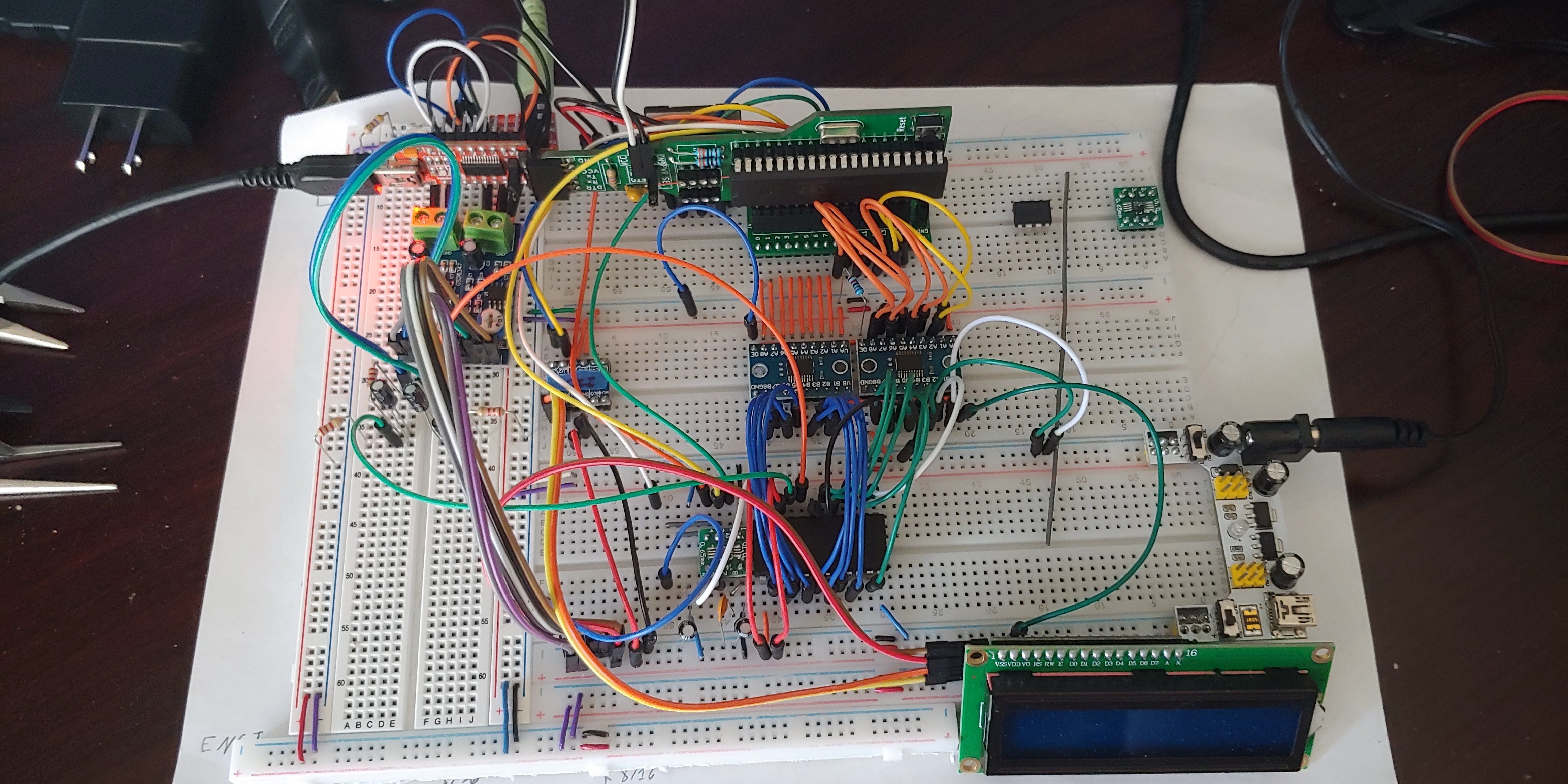
Here's how I have my breadboard setup:
4717a78c59afe0db3ba1a1a934c894.jpg

Been basing the wiring off of this: https://github.com/AidanHockey5/STM32_VGM_Player_YM2612_SN76489
Though with some modifications.
Not using a TPA3122D2 for one.

Any help would be appreciated.

Comments

  • roglohrogloh Posts: 5,119
    edited 2019-08-24 23:14
    I'd recommend carefully checking your wiring to the YM2612 from the propeller driving it. Ensure data bit order and address pins are correct. You might like to post your Propeller code outputting this test program's register sequence and the pin mapping in your implementation to see if anyone sees anything wrong with it. A schematic of your own Propeller based implementation could be useful too, even if simplified. If you have a logic analyser it could be used to probe the signals right at the YM2612 and data writes can be captured to confirm against the expected values. Maybe the breadboard wiring has an error or there is noise somewhere corrupting your register writes. You could also probe with an oscilloscope to check the voltages/waveforms of data and control pins of the YM2612 to see if they look good. The propeller only outputs 3.3V so there may potentially be logic level issues if the YM2612 device requires a true 5V level and is not happy with 3.3V. It's ok if it is just expecting 5V TTL logic level devices to drive it, but a 5V CMOS part won't have as much noise margin if driven from 3.3V CMOS, and could have problems.

    Edit: I see you have listed the TXS0108E in your parts, so you've probably covered the 3.3V to 5V translation issue.
  • Also check your YM2612 clock being output from the LTC6903 is present and at the expected value, if that part is driving its clock. You could also slow down your I/O transitions from the Propeller for the write strobe pulses with delays in case there are signal integrity issues with higher capacitance on breadboards etc. Your wires look reasonably short already but it might be worth a shot. You can probably just slow down the Prop clock to achieve this, so try operating at 5-10MHz instead of 80MHz for example. Check if there are any requirements for startup delay initialisation of the YM2612 as well and that you are adhering to those. If you have tried all these things already and all the input signals at the YM2616 look good on the scope and analyzer, not really sure what else could be wrong unless the test program you are using is incorrect/incomplete, or you have a bad part.
  • I've got a logic analyzer on the way. Data bus is connected to pins 0 to 7 in the same order as the YM2612 (0 to 0, etc).
    I've attached the program that i've been using for testing, though im making more modifications to it atm.
    It's using PropWare for it as i find it easy to work with.
    Though i'm using a Character LCD with an I2C backpack to output debug data and will be making adjustments to it.
    The wierd thing is, when im using PropWare's PWM on a pin to drive the clock of the YM2612 (either direct or through a TXS0108E), it doesnt have the overarching tone that is played but doesnt really play the audio correctly either.
    Im thinking it's either that i have a bad YM2612 or I'm doing something stupid.
  • Hopefully the logic analyzer should help you solve it...
  • Well... it's one of those sub $10 24MHz cheapo logic analyzers... so... yea...
  • Better than nothing.
  • Im getting somewhere!
    Turns out that PropWare SPI code doesnt work right for the LTC6903 and had to code my own to deal with it specifically.
    uint16_t currBit = 0x8000; //0b1000 0000 0000 0000
    uint8_t pos = 15;
    
    while (currBit != 0) {
    	if ((data & currBit) >> pos) this->_SDI.high();
    	else this->_SDI.low();
    
    	currBit >>= 1; //shift the bit we are looking at
    	pos -= 1; //decrease the position to shift the bit to be a boolean
    
    	waitcnt(MICROSECOND * LTC_DELAY + CNT);
    	this->_SCK.high();
    	waitcnt(MICROSECOND * LTC_DELAY + CNT);
    	this->_SCK.low();
    }
    

    It gets rid of the high pitched tone and actually makes sound.
    The issue is that it sounds slowed downed.
    I believe i need a nanosecond timer but the closest i can get is within 100 microseconds.
  • This is what i can get at the moment.
    Looks like it is working yet i think im not sending the data fast enough or that im not delaying data enough.
  • alatnet wrote: »
    Im getting somewhere!
    Turns out that PropWare SPI code doesnt work right for the LTC6903 and had to code my own to deal with it specifically.
    uint16_t currBit = 0x8000; //0b1000 0000 0000 0000
    uint8_t pos = 15;
    
    while (currBit != 0) {
    	if ((data & currBit) >> pos) this->_SDI.high();
    	else this->_SDI.low();
    
    	currBit >>= 1; //shift the bit we are looking at
    	pos -= 1; //decrease the position to shift the bit to be a boolean
    
    	waitcnt(MICROSECOND * LTC_DELAY + CNT);
    	this->_SCK.high();
    	waitcnt(MICROSECOND * LTC_DELAY + CNT);
    	this->_SCK.low();
    }
    

    It gets rid of the high pitched tone and actually makes sound.
    The issue is that it sounds slowed downed.
    I believe i need a nanosecond timer but the closest i can get is within 100 microseconds.

    The copy of your code that I downloaded last night contains this line:
    PropWare::SPI spibus_osc(MISO, MISO, SCLK);
    

    I'll assume that you've actually got it wired correctly, such that the value of "MISO" is actually referring to the data pin going from the Prop to the LTC6903.

    However, even if it is wired correctly, this won't work. In PropWare::SPI's constructor, MOSI is first set as an output, and then MISO is as an input. This means that, after the SPI bus is constructed, you've left your data pin as an input and no data will be coming out of it. You should, instead, write the constructor like so:
    PropWare::SPI spibus_osc(MISO /* or better yet, `MOSI` */, PropWare::Pin::Mask::NULL_PIN, SCLK);
    
  • That's... a really wierd way of doing it...
    Im looking at the code and i dont see that the SPI class even sets the direction of the pins.
    I was under the impression that it would set the pin directions automatically to facilitate it's function.
  • alatnet wrote: »
    That's... a really wierd way of doing it...
    Im looking at the code and i dont see that the SPI class even sets the direction of the pins.
    I was under the impression that it would set the pin directions automatically to facilitate it's function.

    The PropWare::set_mosi() and PropWare::set_miso() methods also set the directions for those pins.
    SPI (const Pin::Mask mosi = Pin::Mask::NULL_PIN, const Pin::Mask miso = Pin::Mask::NULL_PIN,
         const Pin::Mask sclk = Pin::Mask::NULL_PIN, const uint32_t frequency = DEFAULT_FREQUENCY,
         const Mode mode = Mode::MODE_0, const BitMode bitmode = BitMode::MSB_FIRST)
            : m_mode(mode),
              m_bitmode(bitmode) {
        this->set_mosi(mosi);
        this->set_miso(miso);
        this->set_sclk(sclk);
        this->set_clock(frequency);
    }
    
    void set_mosi (const Port::Mask mask) {
        SPI::reset_pin_mask(this->m_mosi, mask);
    }
    
    void set_miso (const Port::Mask mask) {
        SPI::reset_pin_mask(this->m_miso, mask);
        this->m_miso.set_dir_in();
    }
    
    void set_sclk (const Port::Mask mask) {
        SPI::reset_pin_mask(this->m_sclk, mask);
        this->set_mode(this->m_mode);
    }
    
    static void reset_pin_mask (Pin &pin, const Port::Mask mask) {
        pin.set_dir_in();
        pin.set_mask(mask);
        pin.set();
        pin.set_dir_out();
    }
    

    So it does set the pin direction "automatically" but it only does it once. No need to set the direction every time a shift in/out routine is called - that's just wasteful :).
  • First, where did you find the two sound makers? And second that's an amazing setup. Third and most important of all, is it possible to label who everything is on that photo?


    Incidentally I am familiar within reason with the TI part, it and its many kin are extremely capable of making the most amazing sounds.
  • alatnetalatnet Posts: 80
    edited 2019-08-25 21:27
    dont know why but i cant upload an image...
    anyway.
    The green board at the top is a custom board that i made to work with the propeller on a breadboard more easily.
    In the middle is an I2C level translator and two TXS0108E level translator to protect the propeller from 5v.
    At the bottom is an LTC6903 on the left and a YTM2612 on the right with a 16x2 character lcd that uses an I2C backpack. (Above the character lcd is a cheapo breadboard power supply).
    To the left is the two LM386 Micro Amps to deal with increasing the volume of the YM2612, though i've adjusted wiring a bit there atm.
    You cant really see it that much but above the micro amps and behind the usb to serial adapter is a TRRS board so that i can output the audio from the amps to my computer.

    Oh yea!
    DavidZemon wrote: »
    PropWare::SPI spibus_osc(MISO, MISO, SCLK);
    

    I'll assume that you've actually got it wired correctly, such that the value of "MISO" is actually referring to the data pin going from the Prop to the LTC6903.

    However, even if it is wired correctly, this won't work. In PropWare::SPI's constructor, MOSI is first set as an output, and then MISO is as an input. This means that, after the SPI bus is constructed, you've left your data pin as an input and no data will be coming out of it. You should, instead, write the constructor like so:
    PropWare::SPI spibus_osc(MISO /* or better yet, `MOSI` */, PropWare::Pin::Mask::NULL_PIN, SCLK);
    
    This is slightly incorrect.
    MISO stands for Master In Serial/Slave Out and MOSI stands for Master Out Serial/Slave In.
    Master being the propeller in this case.
    So, if i want to send data from the propeller to the LTC, i would need to use the MOSI pin.
    With an SD card, DO is MISO and DI is MOSI.

    EDIT: Ok, there's a lot of conflicting information about the spi pinout with an sd card...
  • alatnet wrote: »
    dont know why but i cant upload an image...
    anyway.
    The green board at the top is a custom board that i made to work with the propeller on a breadboard more easily.
    In the middle is an I2C level translator and two TXS0108E level translator to protect the propeller from 5v.
    At the bottom is an LTC6903 on the left and a YTM2612 on the right with a 16x2 character lcd that uses an I2C backpack. (Above the character lcd is a cheapo breadboard power supply).
    To the left is the two LM386 Micro Amps to deal with increasing the volume of the YM2612, though i've adjusted wiring a bit there atm.
    You cant really see it that much but above the micro amps and behind the usb to serial adapter is a TRRS board so that i can output the audio from the amps to my computer.

    Oh yea!
    DavidZemon wrote: »
    PropWare::SPI spibus_osc(MISO, MISO, SCLK);
    

    I'll assume that you've actually got it wired correctly, such that the value of "MISO" is actually referring to the data pin going from the Prop to the LTC6903.

    However, even if it is wired correctly, this won't work. In PropWare::SPI's constructor, MOSI is first set as an output, and then MISO is as an input. This means that, after the SPI bus is constructed, you've left your data pin as an input and no data will be coming out of it. You should, instead, write the constructor like so:
    PropWare::SPI spibus_osc(MISO /* or better yet, `MOSI` */, PropWare::Pin::Mask::NULL_PIN, SCLK);
    
    This is slightly incorrect.
    MISO stands for Master In Serial/Slave Out and MOSI stands for Master Out Serial/Slave In.
    Master being the propeller in this case.
    So, if i want to send data from the propeller to the LTC, i would need to use the MOSI pin.
    With an SD card, DO is MISO and DI is MOSI.

    EDIT: Ok, there's a lot of conflicting information about the spi pinout with an sd card...

    I've always felt that MOSI/MISO are, by far, the least confusing way to refer to pins in an SPI bus. The master is, by definition, the one driving the clock. With PropWare's SPI object, that is always the Propeller. Therefore MOSI and MISO are unambiguously defined with the Propeller as master..
  • So, been messing with the YM2612.
    Getting some progress but ultimately no audio out at all.
    Dont really know what im doing wrong.
    Either way, I was looking through the documentation for the YM3438 and the Sega2.doc that's floating around and created a header file with defines for the various registers along with some notes about them.
    Figured they might be useful for those that are also working with the YM2612.
    Though some of the ascii diagrams might be a bit wonky... Should be fine in visual studio.
    //Created based off of the documents of the YM3438 and sega2.doc.
    //Created by alatnet on the parallax propeller 1 fourms.
    #ifndef __YM2612_DEFINES_H
    #define __YM2612_DEFINES_H
    
    #pragma once
    
    //LFO
    #define LFO_REG 0x22
    #define LFO_DISABLE 0 << 3
    #define LFO_ENABLE 1 << 3
    #define LFO_FREQ(x) x & 0x07 //Extracts Frequency from 8 bit number
    #define LFO_3_98 LFO_FREQ(0) //3.98Hz
    #define LFO_5_56 LFO_FREQ(1) //5.56Hz
    #define LFO_6_02 LFO_FREQ(2) //6.02Hz
    #define LFO_6_37 LFO_FREQ(3) //6.37Hz
    #define LFO_6_88 LFO_FREQ(4) //6.88Hz
    #define LFO_9_63 LFO_FREQ(5) //9.63Hz
    #define LFO_48_1 LFO_FREQ(6) //48.1Hz
    #define LFO_72_2 LFO_FREQ(7) //72.2Hz
    
    //Timer A (10-bit)
    #define TIMER_A_MSB_REG 0x24
    #define TIMER_A_LSB_REG 0x25
    #define TIMER_A_MSB(x) x & 0x00FF //Extracts MSB from 16 bit number
    #define TIMER_A_LSB(x) x & 0x0300 >> 8 //Extracts LSB from 16 bit number
    
    //Timer B (8-bit)
    #define TIMER_B_REG x026
    
    //CH3/6 Mode - Timers
    #define CH3_6_MODE_TIMERS_REG 0x27
    #define CH3_MODE(x) x << 6
    #define CH3_NORMAL CH3_MODE(0)
    #define CH3_SPECIAL CH3_MODE(1)
    #define CH3_ILLEGAL_A CH3_MODE(2)
    #define CH3_ILLEGAL_B CH3_MODE(3)
    #define TIMER_A 0
    #define TIMER_B 1
    #define RESET_TIMER(x) 1 << x + 4
    #define RESET_TIMER_A RESET_TIMER(TIMER_A)
    #define RESET_TIMER_B RESET_TIMER(TIMER_B)
    #define ENABLE_TIMER(x) 1 << x + 2
    #define DISABLE_TIMER(x) 0 << x + 2
    #define ENABLE_TIMER_A ENABLE_TIMER(TIMER_A)
    #define ENABLE_TIMER_B ENABLE_TIMER(TIMER_B)
    #define DISABLE_TIMER_A DISABLE_TIMER(TIMER_A)
    #define DISABLE_TIMER_B DISABLE_TIMER(TIMER_B)
    #define LOAD_TIMER(x) 1 << x
    #define STOP_TIMER(x) 0 << x
    #define LOAD_TIMER_A LOAD_TIMER(TIMER_A)
    #define LOAD_TIMER_B LOAD_TIMER(TIMER_B)
    #define STOP_TIMER_A STOP_TIMER(TIMER_A)
    #define STOP_TIMER_B STOP_TIMER(TIMER_B)
    
    //Key On/Off
    #define KEY_REG 0x28
    #define KEY_CH(x) x
    #define KEY_CH1 KEY_CH(0)
    #define KEY_CH2 KEY_CH(1)
    #define KEY_CH3 KEY_CH(2)
    #define KEY_CH4 KEY_CH(4)
    #define KEY_CH5 KEY_CH(5)
    #define KEY_CH6 KEY_CH(6)
    #define KEY_OP(x) x << 4
    #define KEY_OP_OFF KEY_OP(0)
    #define KEY_OP1 KEY_OP(1)
    #define KEY_OP2 KEY_OP(2)
    #define KEY_OP3 KEY_OP(4)
    #define KEY_OP4 KEY_OP(8)
    #define KEY_OP_ALL KEY_OP1 | KEY_OP2 | KEY_OP3 | KEY_OP4
    
    //DAC
    #define DAC_REG 0x2A
    #define DAC_EN_REG 0x2B
    #define DAC_ENABLE 1 << 7
    #define DAC_DISABLE 0 << 7
    
    //Entries CH 1-3
    #define CH1_OP1 0
    #define CH2_OP1 1
    #define CH3_OP1 2
    #define CH1_OP2 4
    #define CH2_OP2 5
    #define CH3_OP2 6
    #define CH1_OP3 8
    #define CH2_OP3 9
    #define CH3_OP3 10
    #define CH1_OP4 12
    #define CH2_OP4 13
    #define CH3_OP4 14
    
    //Entries CH 4-6
    ///When A1 is 1
    #define CH4_OP1 0
    #define CH5_OP1 1
    #define CH6_OP1 2
    #define CH4_OP2 4
    #define CH5_OP2 5
    #define CH6_OP2 6
    #define CH4_OP3 8
    #define CH5_OP3 9
    #define CH6_OP3 10
    #define CH4_OP4 12
    #define CH5_OP4 13
    #define CH6_OP4 14
    
    //Detune & Multiple
    #define DT1MUL_REG(x) 0x30 + x
    #define DT1(x) x << 4
    #define MUL(x) x
    #define DT1_NOCHANGE_P DT1(0) //No Change
    #define DT1_x1_E_P DT1(1) //x(1+E)
    #define DT1_x1_2E_P DT1(2) //x(1+2E)
    #define DT1_x1_3E_P DT1(3) //x(1+3E)
    #define DT1_NOCHANGE_N DT1(4) //No Change
    #define DT1_x1_E_N DT1(5) //x(1-E)
    #define DT1_x1_2E_N DT1(6) //x(1-2E)
    #define DT1_x1_3E_N DT1(7) //x(1-3E)
    
    //Total Level
    #define TOTAL_LEVEL_REG(x) 0x40 + x
    #define TL_REG(x) 0x40 + x //Alt Name
    #define TOTAL_LEVEL_MAX 0
    #define TOTAL_LEVEL_MIN 127
    #define TL_MAX 0 //Alt Name
    #define TL_MIN 127 //Alt Name
    
    //Rate Scaling - Attack Rate
    #define RS_AR_REG(x) 0x50 + x
    #define RS(x) x << 6
    #define AR(x) x
    #define RATE_KC8 RS(0) //2xRate+(KC/8)
    #define RATE_KC4 RS(1) //2xRate+(KC/4)
    #define RATE_KC2 RS(2) //2xRate+(KC/2)
    #define RATE_KC1 RS(3) //2xRate+(KC/1)
    
    //First Decate Rate - Amplitude Modulation
    #define D1R_AM_REG(x) 0x60 + x
    #define D1R(x) x
    #define ENABLE_AM 1 << 7
    #define DISABLE_AM 0 << 7
    
    //Secondary Decay Rate
    #define D2R_REG(x) 0x70 + x
    #define D2R(x) x
    
    //Secondary Amplitude - Release Rate
    #define D1L_RR_REG(x) 0x80 + x
    #define D1L(x) x << 4
    #define RR(x) x
    
    //Proprietary
    //Envelope Generator
    #define PROPRIETARY_REG(x) 0x90 + x
    #define PRO_REG(x) 0x90 + x //Alt Name
    #define SSG_EG_REG(x) 0x90 + x
    #define SSG_EG_OFF 0
    #define SSG_EG_EN 0x08
    #define SSG_EG_ATK 0x04
    #define SSG_EG_ALT 0x02
    #define SSG_EG_HLD 0x01
    
    ///Shape: |\|\|\|\|\|
    #define SSG_EG_0 0x08
    
    ///Shape: |\_________
    #define SSG_EG_1 0x09
    
    ///Shape: |\/\/\_
    #define SSG_EG_2 0x0A
    
    ///Shape: |\|¯¯¯¯¯¯¯¯
    #define SSG_EG_3 0x0B
    
    ///Shape: /|/|/|/|/|/|
    #define SSG_EG_4 0x0C
    
    ///Shape: /¯¯¯¯¯¯¯¯¯¯¯
    #define SSG_EG_5 0x0D
    
    ///Shape: /\/\/
    #define SSG_EG_6 0x0E
    
    ///Shape: /|__________
    #define SSG_EG_7 0x0F
    
    //Frequency Channels
    #define FREQ_CH1 0
    #define FREQ_CH2 1
    #define FREQ_CH3 2
    ///When A1 is 1
    #define FREQ_CH4 0
    #define FREQ_CH5 1
    #define FREQ_CH6 2
    //#define FREQ_CH4 2 //Maybe?
    ///used with CH3 supplementary frequency
    #define FREQ_CH3_OP2 0
    #define FREQ_CH3_OP3 1
    #define FREQ_CH3_OP4 2
    ///When A1 is 1
    ///used with CH6 supplementary frequency
    #define FREQ_CH6_OP2 0
    #define FREQ_CH6_OP3 1
    #define FREQ_CH6_OP4 2
    
    //Frequency
    #define FREQ_LSB_REG(x) 0xA0 + x //8 bit
    #define FREQ_MSB_REG(x) 0xA4 + x //3 bit Octive and 3 bit MSB
    #define FREQ_CH3_SUP_NUM_LSB_REG(x) 0xA8 + x
    #define FREQ_CH3_SUP_NUM_MSB_REG(x) 0xAC + x
    #define FREQ_CH6_SUP_NUM_LSB_REG(x) 0xA8 + x ///When A1 is 1
    #define FREQ_CH6_SUP_NUM_MSB_REG(x) 0xAC + x ///When A1 is 1
    #define FREQ_LSB(x) x
    #define FREQ_MSB(x) x
    #define OCTIVE(x) x << 3
    //defines to deal with a 16 bit number for frequency and octive
    #define FREQ_LSB_E(x) x & 0x00FF //extracts LSB from 16 bit number and converts it into an 8 bit number
    #define FREQ_MSB_E(x) (x & 0x0700) >> 8 //extracts MSB from 16 bit number and shifts it to an 8 bit number
    #define OCTIVE_E(x) (x & 0x3800) >> 8 //extracts Octive from 16 bit number and shifts it to an 8 bit number that can be ored with the MSB
    #define OCTIVE_E8(x) OCTIVE_E(x) >> 3 //extracts Octive from 16 bit number and shifts it to an 8 bit number
    #define FREQ_OC_MSB_E(x) (x & 0x3F00) >> 8 //extracts MSB and Octive from 16 bit number and shifts it to an 8 bit number
    #define FREQ_OC_MSB(x) OCTIVE_E(x) | FREQ_MSB_E(x) //extracts MSB and Octive from 16 bit number and shifts it to an 8 bit number (alternative, may increase clock cycles)
    
    //used with Feedback/Algorithm and Stereo - LFO Sensitivity
    #define CH1 0
    #define CH2 1
    #define CH3 2
    ///When A1 is 1
    #define CH4 0
    #define CH5 1
    #define CH6 2
    
    //Feedback - Algorithm
    #define FB_ALG_REG(x) 0xB0 + x
    #define FEEDBACK(x) x << 3 //How much OP1 feeds back into itself.
    #define ALGORITHM(x) x
    
    ///Distortion guitar, “high hat chopper” (?) bass
    /// 1 -> 2 -> 3 -> 4 ->
    #define ALG0 ALGORITHM(0)
    
    ///Harp, PSG (programmable sound generator) sound
    /// 1 -+
    ///    +-> 3 -> 4 ->
    /// 2 -+
    #define ALG1 ALGORITHM(1)
    
    ///Bass, electric guitar, brass, piano, woods
    ///      1 -+
    ///         +-> 4 ->
    /// 2 -> 3 -+
    #define ALG2 ALGORITHM(2)
    
    ///Strings, folk guitar, chimes
    /// 1 -> 2 -+
    ///         +-> 4 ->
    ///      3 -+
    #define ALG3 ALGORITHM(3)
    
    ///Flute, bells, chorus, bass drum, snare drum, tom-tom
    /// 1 -> 2 -+
    ///         +->
    /// 3 -> 4 -+
    #define ALG4 ALGORITHM(4)
    
    ///Brass, organ
    ///   +-> 2 -+
    /// 1-+-> 3 -+-+
    ///   +-> 4 -+
    #define ALG5 ALGORITHM(5)
    
    ///Xylophone, tom-tom, organ, vibraphone, snare drum, base drum
    /// 1 -> 2 -+
    ///      3 -+->
    ///      4 -+
    #define ALG6 ALGORITHM(6)
    
    ///Pipe organ
    /// 1 -+
    /// 2 -+
    ///    +->
    /// 3 -+
    /// 4 -+
    #define ALG7 ALGORITHM(7)
    
    #define FB_OFF FEEDBACK(0) // Off
    #define FB_PI_16 FEEDBACK(1) // pi/16
    #define FB_PI_8 FEEDBACK(2) // pi/8
    #define FB_PI_4 FEEDBACK(3) // pi/4
    #define FB_PI_2 FEEDBACK(4) // pi/2
    #define FB_PI FEEDBACK(5) // pi
    #define FB_2PI FEEDBACK(6) // 2pi
    #define FB_4PI FEEDBACK(7) // 4pi
    
    //Stereo - LFO Sensitivity
    #define STEREO_LFO_SEN_REG(x) 0xB4 + x
    #define LEFT 7
    #define RIGHT 6
    #define OUTPUT_ON(x) 1 << x
    #define OUTPUT_OFF(x) 0 << x
    #define LEFT_OUTPUT_ON OUTPUT_ON(LEFT)
    #define LEFT_OUTPUT_OFF OUTPUT_OFF(LEFT)
    #define RIGHT_OUTPUT_ON OUTPUT_ON(RIGHT)
    #define RIGHT_OUTPUT_OFF OUTPUT_OFF(RIGHT)
    #define STEREO_OUTPUT_ON OUTPUT_ON(LEFT) | OUTPUT_ON(RIGHT)
    #define STEREO_OUTPUT_OFF OUTPUT_OFF(LEFT) | OUTPUT_OFF(RIGHT)
    
    #define AMP_SEN(x) x << 4
    #define AMS(x) x << 4 //Alt Name
    #define FREQ_SEN(x) x
    #define PMS(x) x //Alt Name
    
    #define AMP_0 AMP_SEN(0) //0dB
    #define AMP_1_4 AMP_SEN(1) //1.4dB
    #define AMP_5_9 AMP_SEN(2) //5.9dB
    #define AMP_11_8 AMP_SEN(3) //11.8dB
    
    //Alt Name
    #define AMS_0 AMS(0) //0dB
    #define AMS_1_4 AMS(1) //1.4dB
    #define AMS_5_9 AMS(2) //5.9dB
    #define AMS_11_8 AMS(3) //11.8dB
    
    #define FMS_0 FREQ_SEN(0) //0%
    #define FMS_3_4 FREQ_SEN(1) //+-3.4%
    #define FMS_6_7 FREQ_SEN(2) //+-6.7%
    #define FMS_10 FREQ_SEN(3) //+-10%
    #define FMS_14 FREQ_SEN(4) //+-14%
    #define FMS_20 FREQ_SEN(5) //+-20%
    #define FMS_40 FREQ_SEN(6) //+-40%
    #define FMS_80 FREQ_SEN(7) //+-80%
    
    //Alt Name
    #define PMS_0 PMS(0) //0%
    #define PMS_3_4 PMS(1) //+-3.4%
    #define PMS_6_7 PMS(2) //+-6.7%
    #define PMS_10 PMS(3) //+-10%
    #define PMS_14 PMS(4) //+-14%
    #define PMS_20 PMS(5) //+-20%
    #define PMS_40 PMS(6) //+-40%
    #define PMS_80 PMS(7) //+-80%
    
    #endif
    
  • Bit of an update.
    Got my logic analyzer and did some debugging.
    Turns out the TXS0108E were causing data garbage.
    Swapped them for these I2C/SPI mosfet based logic level converters and im seeing the data not get corrupted.
    Need to get audio out working so I'm going to be figuring out how to create an audio circuit for this.
  • kwinnkwinn Posts: 8,697
    alatnet wrote: »
    Bit of an update.
    Got my logic analyzer and did some debugging.
    Turns out the TXS0108E were causing data garbage.
    Swapped them for these I2C/SPI mosfet based logic level converters and im seeing the data not get corrupted.
    Need to get audio out working so I'm going to be figuring out how to create an audio circuit for this.

    Why create an audio circuit when you can buy a stereo module on line for less than the parts to make one would cost.
  • alatnetalatnet Posts: 80
    edited 2019-09-11 00:28
    Bit of an update.
    Looks like for some reason Pin 4 is not outputting ANYTHING.
    This is what it's looking like when i flash the bus:
    Annotation-2019-09-10-195627.png

    As for my layout, it changed a bit:
    20190910_201638.jpg

    For one, i have a logic analyzer now and it's been one hell of a useful tool.
    Also got some new jumper wires that allowed for things to be cleaner.
    Changed the TXS0108E's out for mosfet based level translators and they work great, no garbage at all.
    The jumper wires off the side of them are for the logic analyzer. Makes it easier to connect it.
    4656 x 2328 - 4M
  • Peter JakackiPeter Jakacki Posts: 10,193
    edited 2019-09-11 01:12
    1. Always test your tester, as in swapping the probe lines and seeing if the fault follows the probe, in which case it is a faulty probe.

    2. For goodness sake, what is this obsession with plug-in breadboards? Good double-sided plated through uncommitted pad matrix boards are cheap and freely available. Use socket strips if you like soldered to the matrix board, then plug in your modules. Wire it point to point underneath using Kynar wire (wire-wrap wire) which is very easy to use and solder. Then you have a compact and reliable "board". You can even use more than one board if that suits.

    Here's an example
  • alatnetalatnet Posts: 80
    edited 2019-09-11 01:21
    Oh, i did test it.
    Used pins 9 through 15 for that and it works perfectly.

    And i find breadboards easy to work with. Havent had issues with it and it's something that is reusable without wasting anything.

    Also, tested pin 4 with a volt meter on my custom board, no issues there. Even swapped out the propeller chip itself.
  • Peter JakackiPeter Jakacki Posts: 10,193
    edited 2019-09-11 01:32
    alatnet wrote: »
    Oh, i did test it.
    Used pins 9 through 15 for that and it works perfectly.

    And i find breadboards easy to work with. Havent had issues with it and it's something that is reusable without wasting anything.

    Also, tested pin 4 with a volt meter on my custom board, no issues there. Even swapped out the propeller chip itself.

    I find matrix boards cheap, disposable, and reliable, they can be drilled to suit odd connectors and parts, plus I can package them in a case easily. Whereas plug-in breadboards introduce long leads and capacitance and unreliable connections. Ok for a small and slow circuit but the extent to which they get used leaves me cringing at all the things that can go wrong. Also 0.1" pads make it very easy to solder 0805 caps and resistors pad to pad, nice and close and tight and compact.

    But take this as a useful suggestion, take the leap and try it out and see how well it works (and how very few problems you have with connections).
  • Eh, i consider matrix boards for the next level of prototyping.
    1. Breadboard for quick testing, building the circuit, and confirming that it works.
    2. Then use matrix boards for what you said.
    3. Finally make pcb's.
  • well... F**k me sideways...
    It was a god damn wiring problem...
    I had D4 connected to the clock of the PSG...
Sign In or Register to comment.