

ADC Sampling Breakthrough
 cgracey
Posts: 14,323
cgracey
Posts: 14,323
I've been thinking like mad about how to get good ADC samples.
We all know about oversampling, where you accumulate bits from an ADC for some number of times longer than your desired sample size, then you divide the accumulated value by your oversampling factor. It works okay, but kills bandwidth.
In our case, I noticed that for any reading up to ~4k bits, the sum always had one of four adjacent values for a fixed voltage into the ADC. I realized that this was due to the lumpiness of the bit stream coming from the ADC. It cycles state at least once every 7 clocks. Just grabbing a run of those bits to make a conversion is often like picking it up by sharp ends, since you never know when these periodic rises and falls are going to occur in the data stream, introducing a pointy bias that's costly to oversample away.
So, what if you could oversample 32 times, but on the SAME data at slightly different offsets? To do this is really simple, it turns out. It's kind of a tapered filter. It works like this on a stream of N+32 bits:
(1) Clear sample accumulator.
(2) If bit 0 high, add 1 into accumulator. (This is used by 1 offset.)
(3) If bit 1 high, add 2 into accumulator. (This is used by 2 offsets.)
(4) If bit 2 high, add 3 into accumulator. (This is used by 3 offsets.)
(5) If bits 3..31 high, add 4..32 into accumulator. (These are used by 4..32 offsets.)
(6) If bits 32..N high, add 32 into accumulator. (These are used by all offsets.)
(7) If bit N+1 high, add 32 into accumulator. Now were tapering down.
(8) If bit N+2 high, add 31 into accumulator.
(9) If bit N+3 high, add 30 into accumulator.
(10) If bit N+4..N+32 high, add 29..1 into accumulator. Finish tapering down.
(11) Shift accumulator right by 5 bits to get final sample.
This worked a complete miracle on the ADCs.
I used the streamer to read the ADC pin in on each clock cycle and assemble bytes which got dumped into hub RAM. I could peruse that data and try out different ideas.
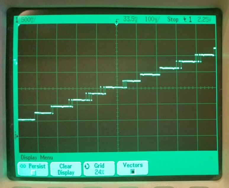
Here is 8-bit-quality sampling of a slowly-rising signal. This detail shows 12 steps in the ADC LSBs:
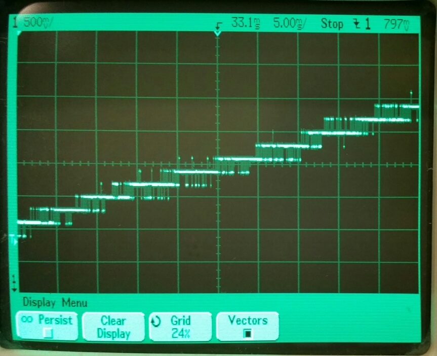
Now look at the same thing, but 12-bit-quality:
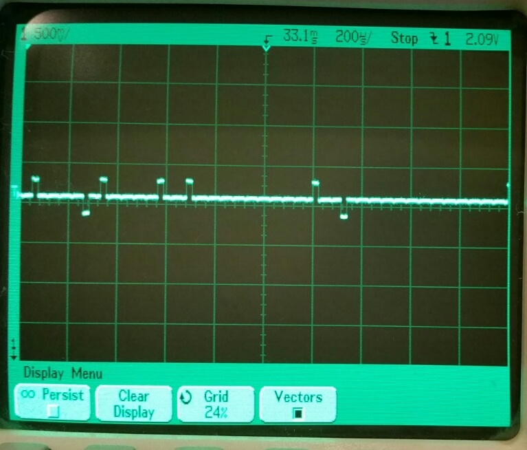
Here is 12-bit-quality sampling of a steady voltage. No wandering, anymore:
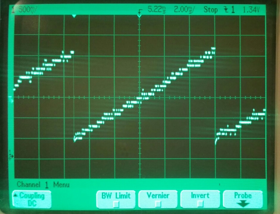
Now here's 13-bit-quality sampling of a 13mV span sawtooth. At 13 bits, 1/f noise starts to become an issue:
Here's my code that runs on the P2 silicon:
We all know about oversampling, where you accumulate bits from an ADC for some number of times longer than your desired sample size, then you divide the accumulated value by your oversampling factor. It works okay, but kills bandwidth.
In our case, I noticed that for any reading up to ~4k bits, the sum always had one of four adjacent values for a fixed voltage into the ADC. I realized that this was due to the lumpiness of the bit stream coming from the ADC. It cycles state at least once every 7 clocks. Just grabbing a run of those bits to make a conversion is often like picking it up by sharp ends, since you never know when these periodic rises and falls are going to occur in the data stream, introducing a pointy bias that's costly to oversample away.
So, what if you could oversample 32 times, but on the SAME data at slightly different offsets? To do this is really simple, it turns out. It's kind of a tapered filter. It works like this on a stream of N+32 bits:
(1) Clear sample accumulator.
(2) If bit 0 high, add 1 into accumulator. (This is used by 1 offset.)
(3) If bit 1 high, add 2 into accumulator. (This is used by 2 offsets.)
(4) If bit 2 high, add 3 into accumulator. (This is used by 3 offsets.)
(5) If bits 3..31 high, add 4..32 into accumulator. (These are used by 4..32 offsets.)
(6) If bits 32..N high, add 32 into accumulator. (These are used by all offsets.)
(7) If bit N+1 high, add 32 into accumulator. Now were tapering down.
(8) If bit N+2 high, add 31 into accumulator.
(9) If bit N+3 high, add 30 into accumulator.
(10) If bit N+4..N+32 high, add 29..1 into accumulator. Finish tapering down.
(11) Shift accumulator right by 5 bits to get final sample.
This worked a complete miracle on the ADCs.
I used the streamer to read the ADC pin in on each clock cycle and assemble bytes which got dumped into hub RAM. I could peruse that data and try out different ideas.
Here is 8-bit-quality sampling of a slowly-rising signal. This detail shows 12 steps in the ADC LSBs:
Now look at the same thing, but 12-bit-quality:
Here is 12-bit-quality sampling of a steady voltage. No wandering, anymore:
Now here's 13-bit-quality sampling of a 13mV span sawtooth. At 13 bits, 1/f noise starts to become an issue:
Here's my code that runs on the P2 silicon:
' ADC tapered-filter sampling

con	p	= 5		'ADC pin, adjacent DAC pin is p^1
	m	= 30		'monitoring DAC pin for watching LSBs of conversion
	s	= $200		'samples/32 per reading ($7FE max)

dat	org

	hubset	##%1_000001_0000011000_1111_10_00	'enable crystal+PLL, stay in 20MHz+ mode
	waitx	##20_000_000/100			'wait ~10ms for crystal+PLL to stabilize
	hubset	##%1_000001_0000011000_1111_10_11	'now switch to PLL running at 250MHz

	wrpin	dacmod,#p^1		'output test level on adjacent pin DAC for ADC input
	wxpin	#1,#p^1
	wypin	dacval,#p^1
	dirh	#p^1

	dirh	#m			'set output for what will be monitoring DAC
'
'
' Get tapered sample
'
loop	callpa	adcmodp,#getsamp	'get pin sample

	mov	x,#0			'reset sample accumulator

	mov	y,#1			'taper up from 1 sample to 32 samples
	rflong	z
	rep	#3,#32
	shr	z,#1		wc
if_c	add	x,y
	add	y,#1

	rep	#4,##s-2		'count middle samples as 32
	rflong	z
	ones	z
	shl	z,#5
	add	x,z

	mov	y,#32			'taper down from 32 samples to 1 sample
	rflong	z
	rep	#3,#32
	shr	z,#1		wc
if_c	add	x,y
	sub	y,#1

	shr	x,#5			'divide sample accumulator by 32 to make tapered average
'
'
' Output result
'
	shl	x,#2			'magnify of LSBs
	sub	x,#55			'add offset (must adjust to center waveform)

	setbyte	dacres,x,#1		'output conversion LSBs to monitoring DAC
	wrpin	dacres,#m

	incmod	modctr,#0	wc	'update the DAC that feeds the ADC
if_c	add	dacval,#$01
	bitl	dacval,#8
	wypin	dacval,#p^1

	jmp	#loop			'loop
'
'
' Get sample
'
getsamp	wrpin	pa,#p			'set ADC mode
	waitx	adcpre			'allow ADC to aclimate
	wrfast	#0,buff			'ready to have streamer write ADC bits into buffer
	xinit	recmode,#0		'do streamer capture of ADC bits
	jnxfi	#$			'wait for streamer command finished
_ret_	rdfast	#0,buff			'ready to read sample longs (lsb=first sample, msb=last)

'
'
' Data
'
adcmodg	long	%100000_0000000_00_00000_0	'ADC gio
adcmodp	long	%100010_0000000_00_00000_0	'ADC pin adjacent
adcmodv	long	%100001_0000000_00_00000_0	'ADC vio

dacmod	long	%10110_00000000_01_00010_0	'DAC 16-bit with random dither
dacres	long	%10110_00000000_00_00000_0	'DAC 8-bit

recmode	long	$D<<28 + p<<17 + s<<5 + $20	'streamer single-pin record command

dacval	long	$8000+15			'DAC value for feeding ADC

adcpre	long	$20				'ADC acclimation period

modctr	long	0

buff	long	$1000				'sample buffer address in hub

x	res	1
y	res	1
z	res	1
Comments
Using this, I'll now look into getting the auto-calibrated sampling going for really mindless instrumentation operation.
With the tapered filter, you get nice single-level samples if you're close to the exact voltage that level represents, with only seldom spikes to adjacent samples.
Will this q32 filter be optional, to allow someone to add a different filter if they find one that better suits their application ?
It will just be a smart pin mode, like the rest.
If they want some other filter, they'd have to do it in software, like I just did.
Right. Sounds like an apt description.
The amount of noise reduction is equal to the square-root of the number of
points in the average. For example, a 100 point moving average filter reduces the noise by a factor of 10.
I wonder how much logic this adds though, I would think it substantial, but I could be wrong.
I guess its easy enough to test, quicker than building a model in this case, since its already working with real hardware and real signals
But, oh jeez, here we go again: more added hardware complexity to further delay deliverable silicon. Where -- and when -- does it end?
-Phil
They have a meeting on the respin with ON in 7 or 8 days, Chip promised to meet that deadline.
The beauty of the P1 is that there are no built-in peripherals, except for the counters. Everything can be done simply in software. The P2 now appears to be getting overstuffed with specialized hardware to what? Simplify things for the user? I really don't get it. But that doesn't mean I can't be sold at some point.
-Phil
I wonder whether this ADC (and other peripheral) routines shouldn't go into the ROM, like a kind of analog BIOS, so they can be called from Taqoz or Cluso's monitor or other code. Also I dare say this trapezoidal filter idea will likely evolve, and ROM changes can apparently be slipped less painfully into the sausage, later in the process.
--
I think you'll like this P2 chip eventually, Phil. I remember my early days with the P1 and the expanse of "what suddenly become possible" and how easy it was to develop quick proof-of-concepts. This P2 chip already has me down at the local coil-makers, talking possibilities and getting custom stuff made.
I'm also (respectfully) suggest that the P1 counters, while brilliant and flexible, still required an AN001 education process to be aware of how to take advantage of them, and the market and online catalogues _still_ think P1 doesn't have any UARTs, nor any timers, nor any ADC capability at all, despite us insiders knowing better.
This is what Digikey says today
See that blank peripherals box? For P2 it'll be important to be recognized straight up for analog, video, streaming /DMA credentials, right from the beginning.
USB, HDMI, SDXC and other licensable tech runs the risk of not being recognized like the P1 counters, but that can be dealt with by paying some fees and creating some definitive IP, if need be.
I am in awe of the streamers ability to create VGA at 1920x1080 with so few instructions. You know what, its such a waste of a cog
I'm pretty certain you have done a second-order filter - except it's chunked rather than windowed, ie: non-moving average.
If you really want to throw a little extra hardware at the problem then I'd recommend doing a double accumulator. You might remember a drawing from the past:
This has three accumulators so is third-order. Ignore the decimators, software handles that.
MOD_CLK there becomes sysclock of the Prop2.
The streamers can be stuffed by interrupts.
We already have video running this way.
The video in my Logic Analyzer does this, even though I haven't taking advantage of the idle time.
Evanh, while that 2nd-order filter diagram looks simple, I haven't been able to get my head around it after many years of trying. Maybe you could explain to me what that thing does.
What we have in this new filter is extremely simple in hardware. You guys have way overblown the issue. This is simply an adder that adds 1 to 32, 32 for a while, then 32 to 1, based on each ADC sample bit. It's nothing to freak out about. I consider it a gift from God, because it's got the ADC's working exactly as they need to for discrete sampling. It's a miracle! I had no expectation that such an improvement would even be possible. The ADC's are exactly where they need to be now.
This is the same except that the double accumulator is not tied to 5 bits and is windowed.
The confusing part is the way the accumulators roll over at an alarming rate. This washes out in the differentiation at the decimator because the summing is circular.
That's the best overview I can muster.
Smartpin mode %01100, "Count A-input highs", with X set for the DEC_CLK period, is exactly as one accumulator and one decimator stage, with its differentiation, from that drawing.
And by setting X to zero it just keeps counting up. Then the decimation, and differentiation, has to be arranged in software.
EDIT: And this shouldn't change the amount summing logic either, since the existing differentiation requires it as well.
http://forums.parallax.com/discussion/comment/1453877/#Comment_1453877
So, as a casual observer, please give rough usefull effective sample rate for someone who wants 12 bit precision ADC in a P2 application. Willing to do software filter.
Because the ADC duty cycle ranges from ~16% to ~84%, ~1/3 the range is of no use within the power rails. So, you'd need to oversample by 1/(2/3), or ~50%. So, that's 2^12 * 1.5, or 6,144 clocks plus 32 for the taper. That's 6,176 clocks.
If we have smart pin filtering, you can pick up a filtered sample every 6,176 clocks.
Without smart pin filtering, you can capture a sample's worth of bits every 6,176 clocks and then process them in software. The time to process in software will be less than the sample time, but it would eat into your CPU time by ~20%. While that's not much, it would be a big bugaboo to have to have the filtering code resident and lose use of the streamer.
So, in either case, at 250MHz, your sample rate could be 250M/6,176, or ~40.5KHz.
That drawing is third-order, not second-order. I just noticed you called it second-order. So, to get second-order, only do two of the three shown stages. And even then only do two accumulators. Forget the decimator stages since software can do those easy.
That way you aren't making it any bigger than existing resources in the smartpins.
EDIT: Here's all that's needed
With a second-order filter, wouldn't we need a 2nd-order integrator? I still have no idea how these things work.