

S3 Rubber-Laser Gun & Educational activities
Hi all,
This is an announce from some activities of this year educational project with my students.
The project uses a 3d printed Rubber-band-gun controlled by S3 robot via hacker port with BlocklyProp
The inspiration project was the "S2 Marauder: 12-shot Semi-automatic ..." from Phil Pilgrim, an amazing rubber Gun for S2.
However I believe that the S3 Hacker Port, the 3d printers and BlocklyProp can make this project suitable and for not advanced makers and programmers.
That exactly was my main effort for that project that is still in progress...
Using that gun with BlocklyProp, I found powerful trigonometric commands that can activate students in order to use Maths better ....
In the next posts I'll give gradually all the activities and details of this project and I expect to improve it through the discussion, your comments and ideas....
For those with a 3d printer the parts are here: https://www.thingiverse.com/thing:2789905
Comments
In order to locate the targets I use the PING)))™ ultrasonic sensor.
The laser that I use, is a simple red Laser Head mini pointer adapted on the edge of gun's barrel.
That laser is connected to the hacker port on P3 Pin and I can control it using the make Pin high/low commands. The purpose of that laser is to know in advance where exactly the rubber will going to hit and warn the users.
It is also useful to test the several angles of the gun during the educational activities without need to throw rubbers every time...
BTW that rubber band hook above your laser diode sticks up a lot and is surely deflecting your rubber band to some degree. Important if you're aiming at small targets. You want a very gentle ramp, if any. As my photo above shows, I favor a straight rod with a fork cut in the end, per sketch.
Nice job, Nikos!
-Phil
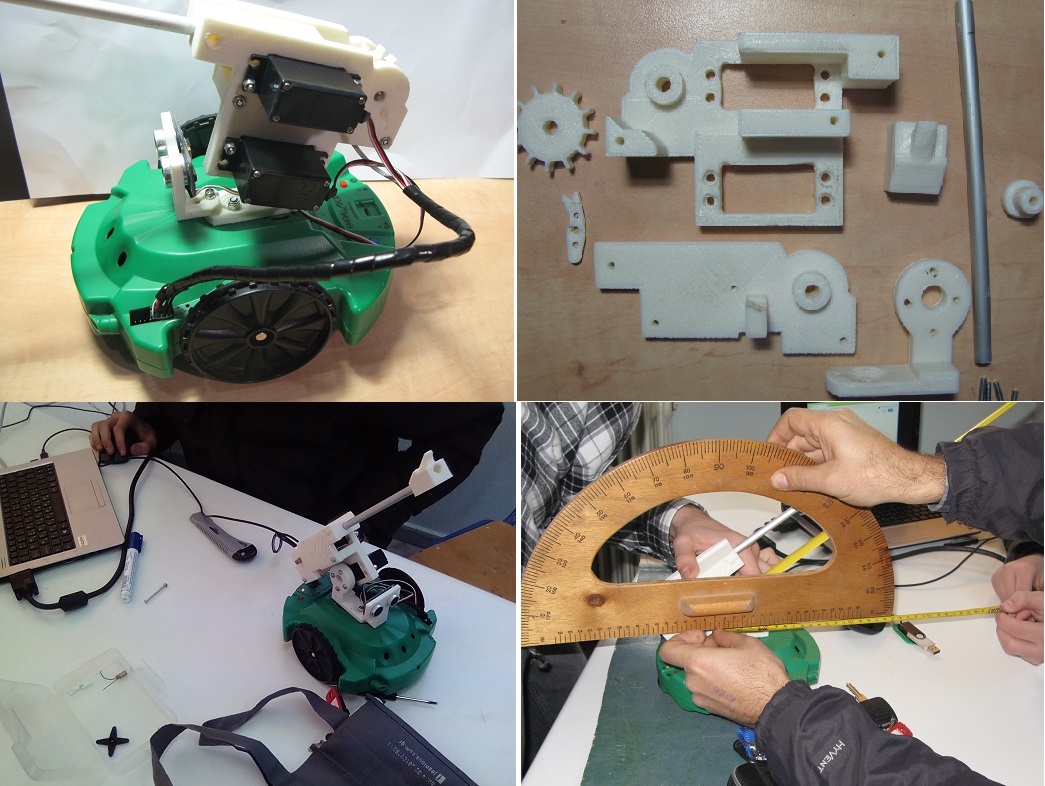
This is not a problem at all. Due to the gun's design you must make the minimum changes on3D printings. The only part you must change is the "S3_rubber_gun_part4" . In the next photo I explain the assembly of the gun's barrel with this part.
It is also very important that you can change the lenght of the aluminum barrel according the rubber's size you have, without change the rest parts of the gun.
So for every change and improvement I provide the Sketchup files.....
1) Two (2) Parallax Standard Servo
2) One PING)))™ ultrasonic sensor (or Ideal The LaserPING 2m Rangefinder)
3) Laser head mini pointer from e-bay (Optional)
4) Aluminum tube (Length:175mm, Ext. diam:8mm, Int diam:5.5mm). You can change the length according rubber size)
5) A barrel 40 mm length 6mm diam for cog's assembly
6) (10) screw 15mm and nuts (for servo and servo horns assembly)
7) (3) srew 40 mm and nut (for gun's main body assembly)
8) Rubber bands (choose the size according gun's barrel length)
video
Targets could be anything however in order to test the shooting angles, targets must have a height. 60 cm is a very good height for close and distance shootinghs .
It is also necessary every target to have a flat area near the base in order to be detectable from PING)) sensor (that area for my targets is 14.5cmX20cm).
The entire target base is wooden and on top of it we can put a paper with the printed target..
-Phil
Thank you Phil!
I think that the activities I'll give on the next posts are able to be done with S3 and Blockly, with both guns : "S2 Marauder" and "S3 Rubber gun". The only thing that students must pay attention is to connect the corresponding parts of each gun in the right Pins in order to "run" properly the blockly code.
Here is my Pin connection:
I also send the image of the target ,for those who want to print one...
In the next post I'll give a simple way to calibrate the tilt of both guns with Blockly and the use of a protractor without any adjustment on the tilt-servo
On activity-01 called Azimuth, the S3 robot must pivot and every time that locate a target toward in front of it, must stop in order to do the activity 02.
On activity-02 called tilt, the S3 is looking toward straight to a target (in a random distance)(that has being solved from activity-01) , and it must ajust the tilt of the gun in order to hit the target.
Both activities that lead to find the target can be solved using data from the PING))) sensor..
The maximum detection area is a circle with the S3 robot as the center, and radius 3m (the PING))) sensor maximum detection limit)
So we can avoid to have walls or other objects inside the detection area.......
However as you said, a person can be identified as a target inside the detection area. The only we can do is to prohibit the acces in that area to the people.
In otther case we need an artificial vision with another sensor able to see the difference
between a man and a target...
Of course we must always have in mind that a rubber that throws the gun can goes out from the detection area....
Maybe also a PIR sensor, if that detects something, the target may be a person, so then you do not fire.
Ken Gracey
We create a table with ServoY and Y values…
ServoY is the angle of the servo and Y is the real tilt of the gun.
We give some random values to the servoY (e.g 80, 60, 45,30) in order to see the produced tilts….
For each one ServoY value we execute the code “Servo Pin P1 set angle (0 ο -180 ο) ServoY” on BlocklyPROP, and then we get a corresponding tilt that we must measure using a protractor in order to complete the table. (for me, the values I got were: 18,38,53,68)
From the table we can see that the sum of values y and servoY is a constant number. For me it was y+servoY=98 (for another user could be a different number but it doesn’t mattet). From that number we can have the Tilt formula (For me it was: ServoY=98-y). In other words every time we want a tilt y degrees, we know the corresponding servo's angle ServoY=98-y
On activity-01 called Azimuth, we put targets randomly, inside a circle with radius =< 3m. The S3 robot must pivot and every time that locate a target toward in front of it, must stop in order to shoot. At the present time we avoid the shooting and we program the S3 only to blink its Led’s and waiting for a while in front of the target before continue the scanning the entire circle.
The procedure is the following: The S3 pivot in a small step (Azimuth step=2 degrees) and simultaneously gets the values X from the Ping sensor that is the distance. Every time that x is smaller than max_detection_area it means that a target has been detected.
Then the S3 light its LEDs for a while and then makes a rotation skip to continue the scanning on the rest part of the circle
https://precisionrbs.com/about-precision-rbs/
A pity Ben's face is never shown below, the blogger hogs all the glory. Loading technique details at 2:20:
When the S3 detect a target, stop the scanning procedure (at this stage the gun it is not centered towards the target). Then the robot turns right for some degrees in order to center the target, then it shoot (light the red LEDs and makes a sound), and finaly skip the target, turning right again for some appropriate degrees.
On BlocklYProp the corresponding program has the name: "Activity 01 Azimuth Rubber gun (NikosG)"
Video
On activity-02 called tilt, the S3 is looking toward straight to a target (in a random distance), and it must adjust the tilt of the gun in order to hit the target.
Here as you can see, we have a right triangle and we know the vertical side (h) (the height of the target, that is constant h=50), and the horizontal side (X) that is the distance between the base of the target and the robot. The horizontal side (X) can be changed but we can know it every time, using the PING))) sensor. On BloclyPROP the command in order to get te value of X is: “ X=Ping)) sensor on P2 distance in centimeters”
The Tilt of the gun is the angle y.
Using trigonometry, we can calculate the Tangent of the angle y, so… Tan(y)=h/y and then the angle y is: y=arc tangent (h/y). On BloclyPROP the command in order to calculate Y is: “arctangent of (h÷X) X 1 store in Y”
In the next experiment we move the target in front of the robot. BloclyPROP using the method we described above can calculate the tilt and change automatically the gun’s position….
Video
Moving the target closer to the robot the tilt is increased. Moving the target away from the robot the tilt is declined... The gun always target the center of the target.
Then, as the height 'h' of the target and 'a' are constants and 'd' is the distance measured by PING, the tilt angle α = atan (h/(a + d)).
BTW, from your earlier target drawing I would think h is closer to 40 cm than 50 cm.
However the rotation center is that with the yellow arrow.... So The "α" you said, is a little bit different.....
In fact we have some "Similar" triangles over there.......
It doesn't matter which of them we are going to take because all of them have the same tilt
I would say that is better keep the smaller one (with the clear d as a side ), and to "play" a little bit with the values of "h" in order to have the best result....