Shop OBEX P1 Docs P2 Docs Learn Events
$5 Line Follower Fun — Parallax Forums

$5 Line Follower Fun

ercoerco Posts: 20,244
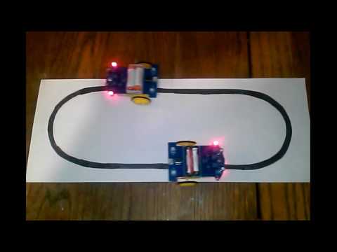
Grab a few of these $4.59 line follower kits before the price goes up, they were $4.36 when I bought on March 31. Once again, the sum of the parts is worth more than that! It's not programmable, just uses an LM393 comparator and two CdS cells to follow a line. Quick & easy build, works right away. It zigzags (alternating left/right motors) in its stock configuration, but I tweaked it and it's smoother & faster now. My video on top, someone else's at bottom.


«1

Comments

  • Wow, $4.59 shipped! I promised no more bots until the rover is done...
  • ercoerco Posts: 20,244
    edited 2017-04-02 20:44
    Just order it now and finish the rover before it arrives! I know your space is gone, but modding & racing these would be perfect for hacker types.

    BTW there are similar kits with IR obstacle avoidance and Bluetooth control.
    http://www.ebay.com/itm/351962461760
  • MikeDYurMikeDYur Posts: 2,176
    edited 2017-04-03 00:44
    That conversion of yours works pretty good, you could put a camera mount on there, and go out on the main floor. I want to incorporate this on a line follower, it looks more confident in it's travels. It doesn't waste time and energy moving in a direction it don't need to go in the first place, which is kind of like travel by over correction. How is the sensor set up? Anything like the home brew line sensor you came up with a while back, reflecting a green LED off the floor back to two CdS cells?

  • I just ordered​ one. I have no intention of building it as a line follower, but at the price is so low I can take the risk of hacking it into something else.
  • ercoerco Posts: 20,244
    edited 2017-04-03 06:44
    Martin_H wrote: »
    I just ordered​ one. I have no intention of building it as a line follower, but at the price is so low I can take the risk of hacking it into something else.

    XLNT. Maybe this becomes another Figure 8 type challenge with simple rules/guidelines, to do something new & different with this chassis. The price is right. Just one, Martin? :)
  • Cluso99Cluso99 Posts: 18,066
    erco,
    I am beginning to think that eBay sellers are watching for you to buy something, and then they raise the price for your followers ;)
  • ercoerco Posts: 20,244
    Or I alert them to my buying recommendations to loyal disciples and cut a deal...
  • Very nice! What was the actual mod you did? The video is a bit blurry.
  • ercoerco Posts: 20,244
    I'm writing that up for SERVO magazine right now! Basically rerouted the comparator inputs so that both motors are on in the straightaways.
  • ercoerco Posts: 20,244
    Unboxing! Hahahaha...

  • erco wrote: »
    Unboxing! Hahahaha...


    We need translation! He spent five minutes talking about what seemed to be the bag the parts came in.
  • ercoerco Posts: 20,244
    The guy is Italian, and it's hysterical how he talks with his hands.

    Many Ebay sellers don't ship to Italy since packages disappear in the mail. So this unboxing video is a rare treat from my favorite country, la mia Italia! If it's from Sicily, even better. Amo Sicilia!
  • ercoerco Posts: 20,244
    Banggood sells a Bluetooth/obstacle detection/line follower version for $11.91, best price I've seen. Several obvious differences from the photo/schematic:

    Worm gear drive vs gearmotor assemblies
    Phototransistor line sensors vs CdS cells
    Microprocessor+comparator vs comparator only
    H-bridges vs single transistor (fwd/reverse vs fwd only)
    14500 Li-Ion battery vs alkaline
    Bluetooth module (duh)

    There may be a treasure hunt involved to track down the smartphone bluetooth tilt-drive app.

    http://www.banggood.com/D2-6-DIY-51-MCU-Smart-Car-Kit-Bluetooth-Remote-Control-Gravity-Sensing-Tracing-Obstacle-Avoidance-p-1108390.html

    d2-6.png
    925 x 760 - 838K
    d2-6.png 838.1K
  • Heater.Heater. Posts: 21,230
    erco,
    The guy is Italian, and it's hysterical how he talks with his hands.
    Ha! That is why he needs video. Unicode won't do for Italian.

    Oh wait, maybe along with all the stupid emoji and color rendering they could add video animations into Unicode for Italian :)
    (Don't tell them I said that, they are crazy enough to do it).

    I used to chuckle at my Italian friend's frantic hand gesturing when he spoke to his family on the phone. "Sergio", I would say, "they can't see you hands moving". Oddly he did not do it so much when speaking English.
  • ercoerco Posts: 20,244
    edited 2017-04-10 14:15
    Where else can you get a swarm of robots (three anyway) for under fourteen bucks? Each bot still needs something to interact with, either a forward-facing flamethrower or a pyrotechnic charge on the rear bumper, maybe both. Will advise.

    BTW the thumbnail shows my simplest mod yet for smooth driving. Cut trace to isolate IC pin 3, then connect pin 3 to the far side of R7.

  • ercoerco Posts: 20,244
    edited 2017-04-18 01:57
    After some online sleuthing for details, I built up one of the fancier $12 units with obstacle sensors and Bluetooth control. The doggone thing actually works! Stock line following is actually worse than the $5 car, but I can tweak that. The Bluetooth app lets your smartphone drive it by buttons or by tilting your phone. Will add a video later.

    erco-approved, nab one for yourself! This one has real H-bridges for reverse, the $5 version has forward only. IMHO this one is a great candidate for hacking, it might be the cheap merit bage robot people have been looking for. The sum of the parts is certainly worth more than $12. Kit comes with a preprogrammed STC15W201S processor. You can learn to program that (UGH) or chuck it and hack on your own favorite processor.

    http://www.banggood.com/D2-6-DIY-51-MCU-Smart-Car-Kit-Bluetooth-Remote-Control-Gravity-Sensing-Tracing-Obstacle-Avoidance-p-1108390.html

    d2-6.png
    750 x 750 - 746K
    d2-6.png 746.4K
  • Well, I got mine and built it...and it's not working right. One motor runs, and covering one of the cells turns off the opposite motor, but then the motor on the same side doesn't turn on. I've examined all the solder joints closely, can't see anything wrong. Putting voltage into the bot at a different point turns on both motors, so the comparator circuit has something mysteriously wrong.

    How should it work when it's off the floor and doesn't see a line?
  • ercoerco Posts: 20,244
    Stock circuit or with my mod?
  • Stock so far. I wanted to see how it ran before I started cutting traces.
  • ercoerco Posts: 20,244
    edited 2017-04-23 16:57
    You should be able to tweak the pots to get both motors going, it's MUCH less sensitive to adjustment in the stock configuration, midrange worked fine on both pots for most of mine. Per the schematic, the photoresistor outputs go to both comparator inputs but flipped +/- so only one is on at a time. Measure the voltage at the photocells (make sure it changes in response to light/dark) and make sure that's getting to the comparator. Also, check that you didn't break a trace or lift a pad at the sensors when soldering, the copper is thin and fragile on this single-side board. These things really need a front bumper on the bold/skid to prevent hitting something and breaking off a photocell or LED, or knocking them out of alignment. I've had to repair mine a few times.
  • ercoerco Posts: 20,244
    Adding the schematic for my mod, but you're right to get it going stock first. It's very sensitive to adjustment after the mod.
    694 x 465 - 124K
  • Out of curiosity, why did you mod only one of the op amp inputs?
  • ercoerco Posts: 20,244
    It was the simplest mod to get some overlap using the stock parts. I did consider two initially, but it turns out that the 1K fixed resistor is a significant percentage of that voltage divider, reducing the effective range of the pot adjustments. So modding both comparator inputs would double the overlap and make pot adjustment even trickier.

    Changing both resistors R7 and R8 to 470 ohms would probably make adjustments easier.
  • ercoerco Posts: 20,244
    I should add that my initial mod shown in the first video was more complicated, as evidenced by the number of wires shown on the bottom. In that first incarnation, I isolated the two comparators so that only the left sensor controlled the left wheel and v/v, and the reference voltage came from the pots. Harder to wire, easier to adjust.

    Calibration procedure for the one-wire mod shown in the schematic 3 posts back:

    The only downside of this simple mod is that adjusting the modified LFR is trickier than the stock unit and requires empirical calibration, i.e., experimenting! Calibration depends on the battery voltage and the physical position of the LEDs and photocells which are hanging out in space and vulnerable to bending, so be careful not to crash or bend them. I run my photocells ~ 0.100” AGL and the LEDs ~0.200” AGL. Use the small oval course printed on the back of the instructions to calibrate. Start with both pots adjusted to their center position. Per Figure 7, the left pot MOSTLY adjusts the right turns and right pot MOSTLY adjusts left turns, although they affect each other and you need to strike a balance. Calibration is an iterative process where you test a right-turn circle (clockwise) and slowly, slightly adjust R2 counterclockwise until it follows the turn properly. Then test a left-turn circle (counterclockwise) and slowly, slightly adjust R1 clockwise until it follows the turn properly. Then go back and retest right and left turns. There is a best balance of pot adjustments which will let the robot track properly right and left. Once you get it dialed in, you can try speeding it up. One of my videos shows that faster speeds come from using higher voltage Li-Ion cell (~4V) compared to the stock 3V alkaline cells (recalibration required). How fast can YOU go?
  • I've gone over the 'bot a couple of times, every solder joint tests out good and the components all seem to be working. Connection from the sensors to the comparator is fine. I've twiddled the pots gradually through their ranges, no change to the one motor.

    No idea. But the last time I had an issue like this, the components were defective (LEDs manufactured backwards - so the flat side went to the wrong pin!)
  • ercoerco Posts: 20,244
    Strange, I've built 3 without issues. Do you get varying voltages out of both sensors and into the comparators when the sensors see black and white?
  • ercoerco Posts: 20,244
    A fellow at robot rebels who has built a dozen says he has received some bad comparators from China: http://www.robotrebels.org/index.php?topic=701.msg3465#msg3465
  • Hmm, so you mean that chip is NOT by TI? ;)

    Jameco is nearby and another chip is only $0.25. Will pick one up in the next day or two.
  • ercoerco Posts: 20,244
    Easy enough to yank the chip and test it on a breadboard. Also with the chip out, you can manually drive socket pins 1 and 7 low and see if the motors turn on.
  • So, with the chip yanked...
    Pin 7 -> GND works (same side as works with the chip in)
    Pin 1 -> GND does not. When grounded the LED flickers briefly.

    So at this point the chip isn't the culprit. Is that the transistor then?
Sign In or Register to comment.