

nRF24L01+ : Having difficult time getting a simple test to work, could use some help/advice.
 Mahonroy
Posts: 175
Mahonroy
Posts: 175
in Propeller 1
Hey guys,
I am in the process of testing out a couple nRF24L01+ modules, but am having some difficulties. First I will explain what I am trying to accomplish with this test:
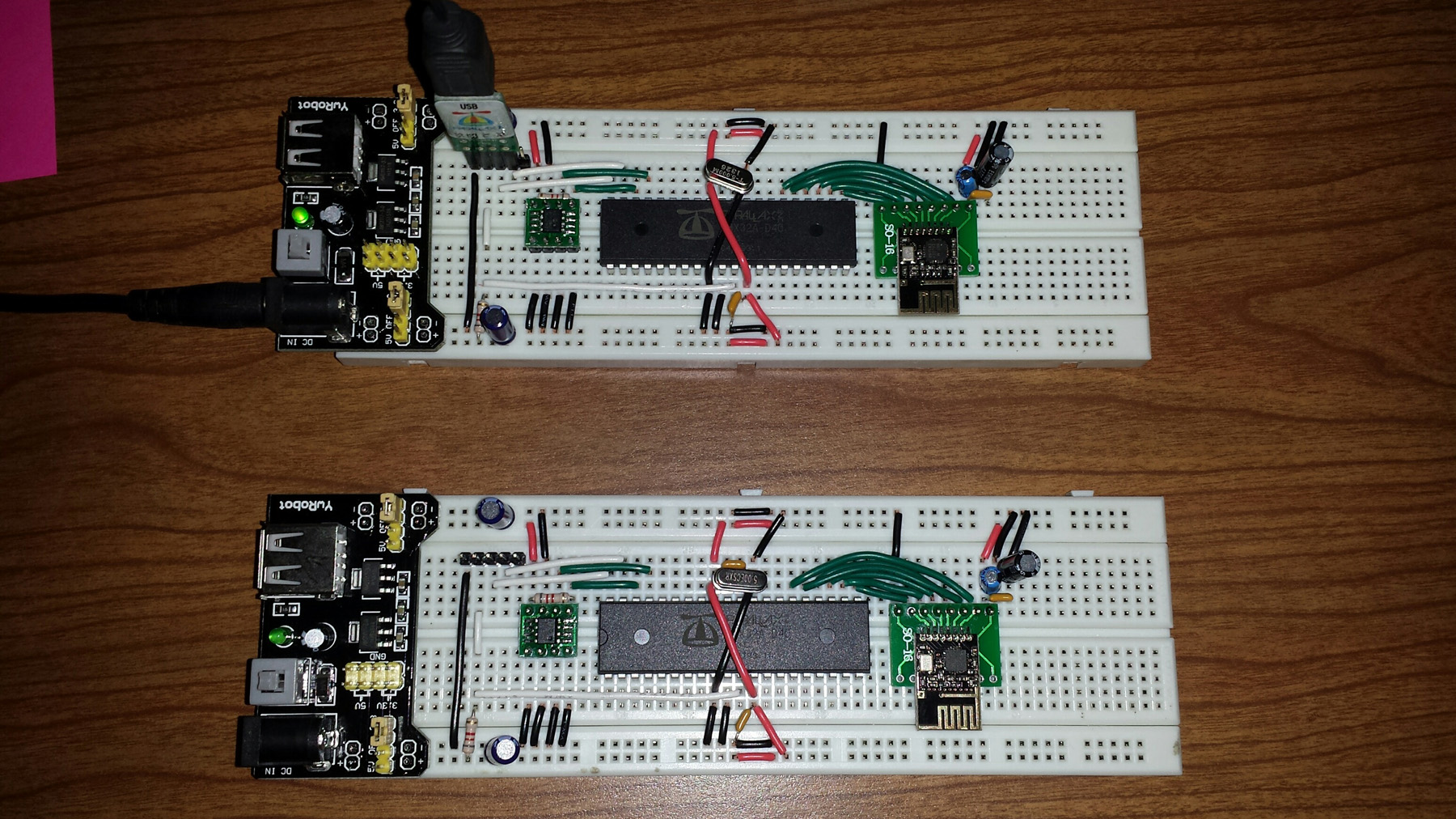
I have 2x propellers, each fitted with its own nRF24L01+ module. One of them is going to just be listening and the other one is just going to be transmitting. The one used for listening is connected to computer via usb cable and has parallax serial terminal running to view what has been received.
Here is a photo showing the setup (I am using the surface mount version of the nRF24L01+, so I just soldered it to an adapter board so I could plug it in):
I read through this tutorial:
http://www.diyembedded.com/tutorials/nrf24l01_0/nrf24l01_tutorial_0.pdf
And I used this as another reference:
https://www.sparkfun.com/datasheets/Components/SMD/nRF24L01Pluss_Preliminary_Product_Specification_v1_0.pdf
I also found this driver & demo in the parallax object exchange:
http://obex.parallax.com/object/432
This object only has the receive portion implemented, so I began modifying it to get a transmit working. I attached all of my code so far.
Using the provided nRF24L01 object, all I am receiving is "00000000", sometimes it takes a couple seconds to get a payload, sometimes I get multiple payloads per second, but they are always all zeros. This is without transmitting anything on the 2nd propeller by the way.
When I do run the 2nd propeller in an attempt to transmit, nothing changes in the receiving portion, still all zeros. Obviously I don't have something configured correctly.
I wanted to add in the functionality so that when the IRQ pin goes low (interrupt pin - indicating an event) I could pull in the status from one of the registers to see what it says. I couldn't figure out how to read the status register.
So I started going through the initializing code in the nRF24L01 object, and it does not seem like the configuration procedures are initializing the correct addresses? For instance look at the "Set PRX, CRC enabled". It sets CNS pin to low, it then sends "$20", followed by "$39". Looking at the sparkfun documentation (page 57 of 78) doesn't it mention that the address is "$00" and not "$20"? So I understand how the "$39" equals to "0011 1001" which corresponds to the settings in the table.
I figured the first step that I should do is to make sure that I can write these settings to the registers, and then read back the settings from the registers for a sanity check, then I can move on to the next step.... but I am having difficulty figuring out how to do that.
Also, do I need to insert some kind of a wait instruction after setting the CE or CSN pins high or low?
I attached my code so far, I would greatly appreciate any insight you might have, thanks!
I am in the process of testing out a couple nRF24L01+ modules, but am having some difficulties. First I will explain what I am trying to accomplish with this test:
I have 2x propellers, each fitted with its own nRF24L01+ module. One of them is going to just be listening and the other one is just going to be transmitting. The one used for listening is connected to computer via usb cable and has parallax serial terminal running to view what has been received.
Here is a photo showing the setup (I am using the surface mount version of the nRF24L01+, so I just soldered it to an adapter board so I could plug it in):
I read through this tutorial:
http://www.diyembedded.com/tutorials/nrf24l01_0/nrf24l01_tutorial_0.pdf
And I used this as another reference:
https://www.sparkfun.com/datasheets/Components/SMD/nRF24L01Pluss_Preliminary_Product_Specification_v1_0.pdf
I also found this driver & demo in the parallax object exchange:
http://obex.parallax.com/object/432
This object only has the receive portion implemented, so I began modifying it to get a transmit working. I attached all of my code so far.
Using the provided nRF24L01 object, all I am receiving is "00000000", sometimes it takes a couple seconds to get a payload, sometimes I get multiple payloads per second, but they are always all zeros. This is without transmitting anything on the 2nd propeller by the way.
When I do run the 2nd propeller in an attempt to transmit, nothing changes in the receiving portion, still all zeros. Obviously I don't have something configured correctly.
I wanted to add in the functionality so that when the IRQ pin goes low (interrupt pin - indicating an event) I could pull in the status from one of the registers to see what it says. I couldn't figure out how to read the status register.
So I started going through the initializing code in the nRF24L01 object, and it does not seem like the configuration procedures are initializing the correct addresses? For instance look at the "Set PRX, CRC enabled". It sets CNS pin to low, it then sends "$20", followed by "$39". Looking at the sparkfun documentation (page 57 of 78) doesn't it mention that the address is "$00" and not "$20"? So I understand how the "$39" equals to "0011 1001" which corresponds to the settings in the table.
I figured the first step that I should do is to make sure that I can write these settings to the registers, and then read back the settings from the registers for a sanity check, then I can move on to the next step.... but I am having difficulty figuring out how to do that.
Also, do I need to insert some kind of a wait instruction after setting the CE or CSN pins high or low?
I attached my code so far, I would greatly appreciate any insight you might have, thanks!
Comments
I don't recall what the problems were, but I remember why back when I first started using these modules finding several large bugs in the OBEX code. As I type this, I recall there was a problem with the return value of the "Read" method (IIRC). The code happened to work with the Nordic FOB but it wouldn't work with larger payloads.
I'll post some other code in a few minutes.
http://forums.parallax.com/discussion/comment/997469/#Comment_997469
The code was written back in 2011 so I'm almost afraid to look at it. I really need to get this code cleaned up. These transceivers are really cheap and really useful.
While I think the code is a bit buggy. I think it does work.
If can't get my code to work, let me know and I'll dig out a couple modules to test it again.
I notice you have this: Where are you getting the "$20" from? It looks like the documentation says the address is "$00"?
Sorry, I don't remember.
I'll try to find some time to look at the code.
I want to send instructions rather than servo signals as you would from a standard rc transmitter.
http://forums.parallax.com/discussion/134143/quickstart-roomba
I was pretty new to programming the Propeller with I wrote the code so I'm not sure how useful it will be. I do remember the code did work. I could activate the Roomba's various cleaning motors remotely and also control the Roomba's speed and direction remotely. I was pretty thrilled with results at the time.
I've worked on and off on my Robot Remote which also uses Nordic nRF24L01+ transceivers.
http://forums.parallax.com/discussion/151023/robot-remote
I wasn't as thrilled with the results of this later project as I had been with the Roomba project.
At present, I only know how to blink an LED in assembly so it'll take me a while to decipher your code. In addition I have to learn SPI.
The upside is I could then potentially build a snow plowing bot that I could control from a desk.
You must understand how to set the config registers, including data byte length to send and rx. You must understand datapipes, as if you send on one datapipe, you can only receive on the same data pipe. Once you are set up, you can send 1 to 32 bytes easily in a packet and the system becomes just like a straight wire for data. But, there is a learning curve if you are trying to roll your own. I printed the manual and had tons of notes on this. Trying to dissect other code will require some working knowledge on this device.
I have my own modules that send, receive, and one that receives and then sends as needed. These were not using the Sparkfun boards on my project. I cannot say how much work it would be to dissect this but at least you can see a working set of files for a sending and receiving unit. The PASM code is similar but may have slight modifications. At least you can clearly see the config registers. If you put in the time you could make this work, but you'd need to either remove code or find out what some of the button pins are and simulate a buttons ie to transmit from the master, a button push is required, so you could remove the code and make the software send at some interval or add a button+pulldown Resistor. Unfortunately I can't hook this up to help you sort it out. The last I recall this code is working as shown.
BTW this is being compiled with BST brads spin tool using optimizing, so you may not get this to compile with the Prop Tool, I can't remember if it was getting pretty large or not.
In the receive Spin file, look at ParsePC and see an example of readstatus.
Range will be a serious issue for trying to run a snow plow with this device, I doubt you will find it the ideal transciever for that role unless it is a tight radius. This code is not doing any error retransmits if there are errors.
I'm not actually going to try to build a remote controlled snow plow. I was commenting on what was possible. I'm more interested in what vanmunch did when he built a mobile bot with an arm and a camera. I think he controlled it with a computer.
FPV and a portable transmitter that sends instructions instead of servo signals are 'game changers' IMO. Range is secondary at this point.
Knowledge is a gift. I don't take it lightly. Thanks to you and Duane Degn for sharing your work.
I am currently in the process of building my own library for this Nordic chip from scratch. This is helping me further understand how everything is working, and I can incorporate better programming practices into the library as well.
I noticed that the STATUS register is being updated, but the IRQ pin is never going low (its high normally, and active low). I was under the impression that whenever a bit in the status register goes from 0 to 1, that the IRQ pin will remain low until the bits are reset (e.g. feeding the status register a 1 in place of the bit to reset it back to 0), does this sound right?
How come the IRQ pin is never going low even when the STATUS register is being updated? Does the IRQ have to be configured to activate on specific interrupts?
After the packet is validated, Enhanced ShockBurst™ disassembles the packet and loads the payload into
the RX FIFO, and asserts the RX_DR IRQ.
Yes, This is one thing I still remember from working with this transceivers.
I am setting the "data pipe 0" payload size to 4 bytes using this:
I am transmitting a payload like this:
      payload[0] := $0A
      payload[1] := $0B
      payload[2] := $0C
      payload[3] := $0D
      nRF.TransmitPayload(@payload)
Here is the code to transmit the payload:
PUB TransmitPayload(payload_ptr) | idx
  'Stop receiving
  Low(SPI_Ce)

  'Flush TX FIFO
  Low(SPI_Csn)
  SpiReadWrite(FLUSH_TX)
  High(SPI_Csn)

  'Load payload
  Low(SPI_Csn)
  SpiReadWrite(W_TX_PAYLOAD)

  repeat idx from 0 to 3  'Payload size = 4 byte
    SpiReadWrite(long[payload_ptr][idx])
  High(SPI_Csn)

  'Transmit payload
  High(SPI_Ce)
  waitcnt(clkfreq / 100 + cnt)
  Low(SPI_Ce)
I get the IRQ status bit letting me know the transmission has sent.
So on the receiving side of things, I have a variable declared as "payload[4]", and I am retrieving data and displaying it to the Parallax Serial Terminal like this:
'Get data
            payload := nRF.ReadPayload
            repeat idx from 0 to 3
              PST.Hex(payload[idx], 2)
And the code for ReadPayload (NOOP = %1111_1111 by the way):
PUB ReadPayload | idx, payload[4]

  'Stop receiving
  Low(SPI_Ce)

  'Read RX payload
  Low(SPI_Csn)
  SpiReadWrite(R_RX_PAYLOAD)

  repeat idx from 0 to 3  'Payload size = 4 byte
    payload[idx] := SpiReadWrite(NOOP)
  High(SPI_Csn)

  'Flush RX FIFO
  Low(SPI_Csn)
  SpiReadWrite($E2)
  High(SPI_Csn)

  'Reset IRQ
  WriteRegister($07,%0100_0000)

  'Start receiving
  High(SPI_Ce)
  return payload
When I run all of this code, I receive a data payload, but I am getting "0A000000", so it looks like I am only getting the very first part of it. Also, when I tried to transmit "1A", "2B", "3C", and "4D" all together, I would receive "1A000000". Is my array screwed up somehow?
Thanks again and any help is greatly appreciated!
SpiReadWrite(long[payload_ptr][idx])
High(SPI_Csn)
'Transmit payload
High(SPI_Ce)
Are you writing 4 longs?
I commented out that piece of code and tried this instead:
I only receive "1A000000". I tried inserting a small delay inbetween each SpiReadWrite and still same result.
I also tried making a function to read the payload width:
This returns "0100_0000" which is 64, so I don't even know whats going on with that, or if I can even get the payload width like that. Pretty lost still.
I will go over it some more... I had a hard time finding this section.
I noticed that when I try this instead:
That it doesn't work... the receiver never actually picks it up and no interrupt occurs. I thought that would be the equivalent?
The nice thing about sending 32 bytes at all time is that you don't have to bother changing the payload size. For many applications you won't notice the time difference between 1 byte sent and 32 bytes. I timed it once and at the highest speeds, you can't tell much difference. So I just leave it at 32 bytes payload. Just load up the payload array with what you want to send and parse however many bytes on the other end.
In my, as I recall I am not using the pin to detect data present, but rather I just constantly scan the status register.
Thanks for the upload, I will go over it tonight.
In the meantime, would you mind answering me this: how come it accepts this:
But it doesn't accept this... isn't this the exact same thing?
So I tried the 32 bytes instead of 4... e.g. "WriteRegister($11,%0010_0000) '32 byte" configures data pipe 0 to be 32 bytes.
I then did this as a test (there are 32 lines each representing 1 byte):
And here is what I received on the other end: