

ThermoProp - A 3-Station Temperature/Humidity Data Logger
 JLocke
Posts: 354
JLocke
Posts: 354
ThermoProp
A 3-Station Temperature/Humidity Logging System Utilizing the Parallax P8X32A Microcontroller
The ThermoProp system consists of three modules, all utilizing a P8X32A (Propeller) microcontroller for a brain. This project originally started as an upstairs/downstairs thermostat, but has morphed into a data logger. I may eventually add a fourth module to interface to my home HVAC system. Currently the system logs temperature & humidity from outside and the upstairs of my house, and only temperature from the downstairs of my house. Data is communicated wirelessly via XBee and logged to μSD every 15 minutes.
The Master unit (Thermo-Master) is located upstairs and contains the µSD card which is used to store the collected data. The Master has a DS1307 Real Time Clock with battery backup (BR1225) and uses a Parallax SHT11 module to read the temperature and humidity. An XBee Wireless RF module is utilized to communicate with remote units. The user interface consists of a single pushbutton (used to set the date/time) and a 4-line by 20-character LCD with the following format:
The Outside unit (Thermo-Slave) is mounted to an outside wall of my house (with a Velcro strip). A location was chosen that is shielded from direct sunlight. The module is powered by 3 AA batteries. Typical battery life is on the order of 70 days. A Sensirion SHT11 temperature/humidity sensor is used to measure the outdoors temperature and humidity. An XBee Wireless RF module transmits the local data to the Master unit. Since it is battery powered, this unit spends most of its time in low-power mode, only waking up every 10 minutes (roughly) to take a reading and transmit the data. Without the power-down, the batteries will only last 7-8 days!
The Downstairs unit (Thermo-Down) is, obviously, located downstairs. The downstairs unit does not measure relative humidity, only temperature. A DS18B20 One-Wire Digital Thermometer is used for the temperature sensing. An XBee Wireless RF module is employed for communication with the Master unit. The user interface consists of a single pushbutton (requests the current date/time and outside temperature from the Master unit) and a 2-line by 16-character LCD with the following format:
When the Master receives the Outside data, it stores it and displays the data on the LCD. It then sends the local (upstairs) temperature to the Downstairs unit. The Downstairs module will store this info and update the data on its own LCD. It will then transmit the local (downstairs) temperature back to the Master unit. The Master again stores the data and updates the LCD.
Every fifteen minutes, on the quarter-hour, the current information is written to a text file on the µSD card, stored comma-separated in a .CSV file. At midnight a new file is created, with the filename in the format of yy-mm-dd.csv. When the new file is created, a header line is also written. A small example of a log file:

ThermoProp System
A 3-Station Temperature/Humidity Logging System Utilizing the Parallax P8X32A Microcontroller
The ThermoProp system consists of three modules, all utilizing a P8X32A (Propeller) microcontroller for a brain. This project originally started as an upstairs/downstairs thermostat, but has morphed into a data logger. I may eventually add a fourth module to interface to my home HVAC system. Currently the system logs temperature & humidity from outside and the upstairs of my house, and only temperature from the downstairs of my house. Data is communicated wirelessly via XBee and logged to μSD every 15 minutes.
The Master unit (Thermo-Master) is located upstairs and contains the µSD card which is used to store the collected data. The Master has a DS1307 Real Time Clock with battery backup (BR1225) and uses a Parallax SHT11 module to read the temperature and humidity. An XBee Wireless RF module is utilized to communicate with remote units. The user interface consists of a single pushbutton (used to set the date/time) and a 4-line by 20-character LCD with the following format:
03/06/13    21:52:14
 UP: 77.1°  H 24.2%
 DN: 80.3°
OUT: 53.2°  H 29.3%
The Outside unit (Thermo-Slave) is mounted to an outside wall of my house (with a Velcro strip). A location was chosen that is shielded from direct sunlight. The module is powered by 3 AA batteries. Typical battery life is on the order of 70 days. A Sensirion SHT11 temperature/humidity sensor is used to measure the outdoors temperature and humidity. An XBee Wireless RF module transmits the local data to the Master unit. Since it is battery powered, this unit spends most of its time in low-power mode, only waking up every 10 minutes (roughly) to take a reading and transmit the data. Without the power-down, the batteries will only last 7-8 days!
The Downstairs unit (Thermo-Down) is, obviously, located downstairs. The downstairs unit does not measure relative humidity, only temperature. A DS18B20 One-Wire Digital Thermometer is used for the temperature sensing. An XBee Wireless RF module is employed for communication with the Master unit. The user interface consists of a single pushbutton (requests the current date/time and outside temperature from the Master unit) and a 2-line by 16-character LCD with the following format:
UP: 77.1°
DN: 80.3°
Pressing the pushbutton will cause the following format to be displayed for 5 seconds:
03/06/13   21:52
OUT:  53.2°
When first powered on, the Master unit will display the current date and time, updated every second, and the local temperature and humidity, updated every 5 seconds. The outdoors unit is the key to the data collection effort. In the battery-powered Outside unit, the Propeller and XBee are put into a low-power mode, with the Propeller doing a slow count. Approximately every 10 minutes, the Propeller powers-up, wakes up the XBee, gets a reading from the SHT11, and transmits the temp/humidity to the Master unit. The Propeller then puts the XBee back to bed, and returns to low-power mode.
When the Master receives the Outside data, it stores it and displays the data on the LCD. It then sends the local (upstairs) temperature to the Downstairs unit. The Downstairs module will store this info and update the data on its own LCD. It will then transmit the local (downstairs) temperature back to the Master unit. The Master again stores the data and updates the LCD.
Every fifteen minutes, on the quarter-hour, the current information is written to a text file on the µSD card, stored comma-separated in a .CSV file. At midnight a new file is created, with the filename in the format of yy-mm-dd.csv. When the new file is created, a header line is also written. A small example of a log file:
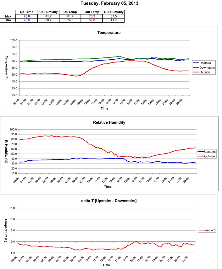
Date,Time,Upstairs (F),Humidity (%),Downstairs (F),Outside (F),Humidity (%)

03/01/13,00:00, 74.4, 28.3, 76.9, 41.7, 44.5
03/01/13,00:15, 74.2, 28.2, 76.7, 41.4, 45.0
03/01/13,00:30, 74.0, 27.9, 76.3, 40.9, 46.0
03/01/13,00:45, 73.6, 27.6, 76.3, 40.7, 46.3
03/01/13,01:00, 73.3, 28.7, 76.1, 40.3, 46.8
03/01/13,01:15, 74.3, 28.5, 76.6, 40.0, 47.0
03/01/13,01:30, 74.7, 28.3, 76.8, 39.8, 47.5
03/01/13,01:45, 74.7, 27.7, 76.9, 39.6, 48.2
The log files are copied from the µSD card, usually once a week. Data is copied to an Excel workbook (a new workbook is created each month) with a tab for each day of the month. Each day tab is identical. The data file is copied into the appropriate worksheet day. The worksheets are constructed to extract minimum/maximum data, and produce line graphs of temperature and humidity related to time of day, as below:
ThermoProp System
- Outside unit sends outside temperature and humidity to Master unit every 10 minutes.
- After receiving the outside information, the upstairs temperature is sent to the Downstairs unit.
- Upon receipt of Upstairs information, Downstairs temperature is transmitted to the Master.
Comments
Hardware
The hardware was constructed on a breadboard for testing, then the schematic was created in Eagle and a circuit board manufactured. All the ICs on the board are mounted in sockets.
Input power is provided from a ‘wall wart’-type adapter, providing 7.5 VDC through a standard 2.1mm DC plug. Voltage regulation is done by an LM2940 providing +5 VDC, and a MIC39100-3.3 regulator providing the +3.3 VDC.
The microcontroller is a Parallax P8X32A (Propeller) in the –D40 package, with the program stored in a 24LC512 Serial EEPROM.
A DS1307 RTC is powered from the +5V rail, and is battery-backed with a BR1225 Lithium coin cell battery.
A Parallax SHT11 temperature/humidity sensor module is mounted on a remote corner of the pcb. The module is powered by 3.3V. The module is mounted in an 8-pin socket on the pcb.
The XBee Wireless RF module is mounted in the required 2mm sockets. It is an Xbee 2mW Series 2.5 Chip Antenna. When I purchased another unit recently for doing some breadboarding, I purchased this as Xbee 2mW PCB Antenna - Series 2 (ZigBee Mesh). The XBee was configured using the X-CTU configuration software and set as ZNET 2.5 COORDINATOR AT.
Connection to the LCD is provided via a three-pin header. The LCD is a 4-line by 20-character format, with a serial backpack (LCD117 from Modern Device, http://shop.moderndevice.com/). The LCD is also powered by +5V.
A two-pin header provides a connection for the pushbutton (normally open) switch. The pushbutton switch input to the Propeller is pulled to ground via a 10K resistor, and goes high (3.3V) upon switch closure. The pin is current-limited via an inline resistor. A small tactile pushbutton is also soldered to the pcb which provides a RESET function for the microcontroller, when pushed.
Software
The main program first initializes the communications (FullDuplexSerial4port), then inits the LCD display. The real-time clock (DS1307_RTCEngine) cog is started and the time is read and stored. Next, cogs are started that read the temperature/humidity (uses Sensirion_full), monitor XBee communications, monitor the pushbutton, and write to µSD (uses fsrw). The program then enters a loop that monitors various flags (SettingRTC, NewOutTemp, NewDwnTemp, NewLocTemp) and calls subroutines based on the state of the flags. It also updates the time display once a second.
cog_LocalTemp
This cog starts the cog for reading the SHT11, then takes a reading from the sensor every 5 seconds. After getting the temp/humidity data, a flag ‘NewLocTemp’ is set, indicating to the main program loop that the LCD should be updated.
cog_Remote
This cog monitors the XBee ‘receive’ line for incoming data. The incoming data is identified by the first character received:
T: this is a request from the downstairs unit for the current date/time and outside temp. A function is called to send the requested data.
O: this is a transmission from the outside unit. The temperature and humidity are parsed from the data string and stored, and a flag set ‘NewOutTemp’ to indicate to the main loop that the outside temperature has updated. The upstairs temperature is sent to the downstairs unit before resuming.
cog_Log
When this cog is launched, it retrieves the date/time info and uses that info to produce a filename in the format ‘yy-mm-dd.csv’. The µSD card is mounted and a file opened. A header indicating “=== REBOOT ===” is written before the standard data header. This indicator is only written at cog initialization and can be used to see that the system restarted for some reason. The cog then enters a loop monitoring the current date/time. On the quarter-hour, the drive is mounted and the current data is written to disk. Each midnight, a new file is opened for that day’s data collection. A data header is written at the top of each new file.
cog_Button
This cog runs in a loop waiting for a button press. When a button press is detected, the cog sets a flag ‘SettingRTC’ to indicate to the main loop that the time-setting function should be called. The time-set routine uses short button presses to increment the current variable (year, month, day, etc) and long button presses to indicate that the current data is correct and to move to the next variable (after setting year, moves to setting month, etc).
PCB layout of Thermo-MasterProp rev. 1.0
Schematic of Thermo-MasterProp rev. 1.0
Hardware
The hardware was constructed on a breadboard for testing, then the schematic was created in Eagle and a circuit board manufactured. All the ICs on the board are mounted in sockets.
Input power is provided from 3 AA batteries, provided through a 2-pin header. The batteries are contained in a standard plastic 3-cell holder. The holder is mounted to the inside of the case with a Velcro strip. Voltage regulation is done by a REG102 low-dropout regulator, providing +3.3 VDC.
The microcontroller is a Parallax P8X32A (Propeller) in the D40 package, with the program stored in a 24LC512 Serial EEPROM.
A 4-pin header provides connection to a Sensirion SHT11 sensor mounted on a remote board. The remote sensor board is drilled to allow use of the Sensirion SF1 Filter Cap. This cap mounts over the sensor and provides protection while still allowing relative humidity measurements. The board is mounted so that only the cap extends through the top of the case, and is sealed with a little Sugru.
An XBee Wireless RF module is mounted in 2mm sockets. It is an Xbee 2mW Series 2.5 Chip Antenna. When I purchased another unit recently for doing some breadboarding, I purchased this as Xbee 2mW PCB Antenna - Series 2 (ZigBee Mesh). The XBee was configured using the X-CTU configuration software and set as ZNET 2.5 ROUTER/END DEVICE AT. The XBee SLEEP_RQ pin is wired to the Propeller, so that the XBee may be put into low-power mode when not needed.
Software
The program first initializes the communications with the XBee (Simple_Serial). A cog for reading the SHT11 is launched, and a cog for data transmission is started. The main program then ends.
cog_Temps
When this cog is launched it starts the SHT11 object (Sensirion_full), then takes a temperature/humidity reading and stores this info in Hub memory.
cog_Send
At startup of this cog, the XBee sleep pin is taken low to wake up the XBee module. After a short delay to allow the XBee to get ready, a function is called which transmits the temperature and humidity values from the Hub memory. After another short wait, the XBee pin is driven high to put the XBee into a low-power mode. After the XBee is sent to sleep, the cog_Temps cog is stopped, and a function is called that drops the Propeller into a low-power mode (running at 5 MHz with no PLL). A loop is entered which counts up to 600 seconds (10 minutes). At the end of the count, the Propeller is returned to 80 MHz with PLL operation, and the cog_Temps cog is restarted. The XBee is then taken out of low-power mode and the temperature/humidity data is sent. The system is returned to low-power mode (as before) and the 10-minute countdown starts again.
PCB layout of Thermo-Slave Prop rev. 2.1
Schematic of Thermo-Slave Prop rev. 2.1
Hardware
The hardware was constructed on a breadboard for testing, then the schematic was created in Eagle and a circuit board manufactured.
Input power is provided from a wall wart-type adapter, providing 5 VDC through a standard 2.1mm DC plug. Voltage regulation is done by an MIC391000-3.3WS providing +3.3 VDC.
The microcontroller is a Parallax P8X32A (Propeller) in the QFP package, with the program stored in a 24LC512 Serial EEPROM. The EEPROM is mounted in a socket.
A three-pin header provides connection to a DS18B20 One-Wire Digital Thermometer. The temperature sensor is mounted in a hole in the top of the case, sealed underneath with a little Sugru.
An XBee Wireless RF module is mounted in 2mm sockets. It is an Xbee 2mW Series 2.5 Chip Antenna. When I purchased another unit recently for doing some breadboarding, I purchased this as Xbee 2mW PCB Antenna - Series 2 (ZigBee Mesh). The XBee was configured using the X-CTU configuration software and set as ZNET 2.5 ROUTER/END DEVICE AT
Connection to the LCD is provided via a three-pin header. The LCD is a 2-line by 16-character format., This is a serial-enabled, 3.3V, White on Black LCD, purchased from Sparkfun Electronics (http://www.sparkfun.com).
A two-pin header provides a connection for the pushbutton (normally open) switch. The pushbutton switch input to the Propeller is pulled to ground via a 10K resistor, and goes high (3.3V) upon switch closure. The pin is current-limited via an inline resistor. A small tactile pushbutton is also soldered to the pcb which provides a RESET function for the microcontroller, when pushed.
Software
The main cog initializes two communications ports (FullDuplexSerial4port), one for communications with the LCD, the other to talk to the XBee. The DS18B20 is then initialized (jm_1-wire) and checked. Other cogs are then started, to read the temperature on a timed basis, to handle sending and receiving data, to keep the LCD updated, and to watch for button presses. The main cog then shuts down, with all of the work being handled by the launched cogs.
cog_Temps
Reads the temperature from the DS18B20 and stores the return in Hub memory, then sets a flag TempUpd to indicate new temperature data. Waits an interval (currently 5 seconds) and repeats.
cog_Display
This cog runs in a loop watching two flags, TempUpd, indicating the local temperature has updated, and NewUpTemp, indicating that the remote (upstairs) temperature has updated. The LCD is then written with the new information.
cog_Remote
This cog monitors the XBee receive line for incoming data. The incoming data is identified by the first character received:
U: the transmission is from the upstairs XBee. The rest of the transmission is parsed and stored as the upstairs temperature and a flag is set NewUpTemp to indicate that data has updated.
T: this is the current date/time and outside temperature, sent from the upstairs unit. The LCD is cleared and the date/time displayed on the first line, with the outside temperature displayed on the second line. After a period of time (currently 5 seconds), the LCD screen returns to the normal upstairs/downstairs temperature display.
This cog also transmits the request for the upstairs temperature data when the appropriate flag (AskForTime) is set.
cog_Button
This cog runs in a loop waiting for a button press. When a button press is detected, the cog sets a flag AskForTime to indicate that the Master unit should be queried for the current date/time and outside temperature.
PCB layout of Thermo-Downstairs QFP rev. 1.0
Schematic of Thermo-Downstairs QFP rev. 1.0
ThermoMaster
ThermoOutside
ThermoDownstairs
Software
Thermo-Master - Archive [Date 2013.03.07].zip
Thermo-Slave Prop - Archive [Date 2013.03.07].zip
ThermoDown - Archive [Date 2013.03.07].zip
ThermoProp XBee Profiles.zip
Blank Month Workbook.xls
This is a great project!
I keep wanting to try something like this.
Thanks for documenting it so well.
Tom
Reminds me of a funny thread a while back. Some poor guy was going broke paying his A/C bill 'cuz his wife & kid were always cranking the thermostat temp way down on hot days. He'd raise the temp setting and leave for work, only to return to a frosty-cold house at day's end. No amount of pleading or reasoning would stop. Think he tried a lock box but they thwarted that too. His last resort was to install a dummy thermostat they could twiddle all they want and hide the real thermostat somewhere else.
Maybe a password encrypted, Bluetooth, hi-fi, wi-fi, real-time, algorithm-controlled, spread spectrum, feed-forward, linear interpolating Linux-based embedded solution thermostat would be in order... Or is there an app for that?
I'll have to ask John if I can let go of the Eagle files, but the schematics are included in the thread.
@Andrew, what are the new Sensiron modules?
Jim
Thermo-MasterProp v22.zip Thermo-MasterProp v22 Gerbers.zip
Thanks for updating the thread, but all your new links are broken.
Nevermind, they are starting to come online. I like the new Master.
Jim, Your picture in the Tachyon thread made me go back and look at John's old threads to see if he had one on that proto board. I didn't get too far, but I found this:
http://idletime.com/PropBreadboard.html
Good luck with that RTC.
I've got the full data logger documented there, as well: http://www.idletime.com/Thermo-Prop.html
That is the exact board that I have. Thanks for the schematic on the board. It will help me trouble shoot the dead one. RTC is running well now that I have cleaned up the wiring and properly installed the pullups.
Jim
Well, I was thinking the SHT21 in the I2C format, but I see that Sensirion obsoleted those and now has SHT3x-DIS series of parts for the format I was thinking of. The part is 2.5mm square, 0.9mm high in an 8 pin DFN package. You can also buy them with a filter membrane already on the part so it's ready to go for IP67. Single piece pricing at Mouser is $5.81 as opposed to the old SHT11 single piece pricing of $16. However, nowadays, most people are using the cheaper Chinese knockoffs like the DHT11/DHT22/CM23022 that are using a thermistor with built in MCU to provide temps.
Jim