

DVI or HDMI shield with true color output: 4.3" plugin works too
 Rayman
Posts: 16,402
Rayman
Posts: 16,402
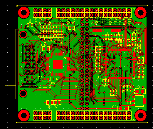
This one has taken me several days to design and it'll be a minor miracle if it actually works:
Update: It actually works!
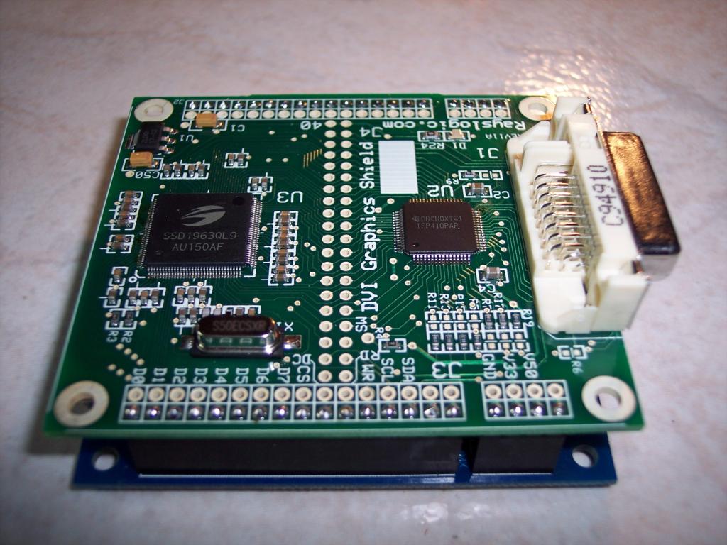
There are only 2 chips and voltage regulator on this Propeller Platform compatible shield.
The chip on the left (Texas Instruments TFP410) drives the DVI connector on the left edge of the board.
The chip on the right (Solomon SSD1963) delivers 640x480 (essentially VGA) with true color, 24 bits per pixel.
Not even Prop2 will be able to do this without external chips.
Here's a new demo video:

Here's what it looks like on the Prop Platform USB:
Update: Just finished up testing the 4.3" touchscreen plugin module and it works too (see post #77 for photos).
So, there will soon be both analog VGA and 4.3" TFT plugin modules for this board available soon.
Another Update: 4.3" touchscreen plugin also works with Newhaven 5" touchscreens with 800x480 resolution.
The capacitive touch version can also work by using a small adapter board to connect the touch connector the DVI shield.
Product Page: http://www.rayslogic.com/Propeller/Products/DviGraphics/DVI.htm
Update: It actually works!
There are only 2 chips and voltage regulator on this Propeller Platform compatible shield.
The chip on the left (Texas Instruments TFP410) drives the DVI connector on the left edge of the board.
The chip on the right (Solomon SSD1963) delivers 640x480 (essentially VGA) with true color, 24 bits per pixel.
Not even Prop2 will be able to do this without external chips.
Here's a new demo video:
Here's what it looks like on the Prop Platform USB:
Update: Just finished up testing the 4.3" touchscreen plugin module and it works too (see post #77 for photos).
So, there will soon be both analog VGA and 4.3" TFT plugin modules for this board available soon.
Another Update: 4.3" touchscreen plugin also works with Newhaven 5" touchscreens with 800x480 resolution.
The capacitive touch version can also work by using a small adapter board to connect the touch connector the DVI shield.
Product Page: http://www.rayslogic.com/Propeller/Products/DviGraphics/DVI.htm
Comments
What are their part numbers ?
I've used the TFP410 before, so I'm fairly confident that half of the circuit will work.
The SSD1963, however, is designed to drive TFT LCD panels and not VGA monitors.
I think people have tried to use the SSD1963 for analog VGA, but I could not find any reports of success.
As far as I can tell, I'm the first to try it for DVI/HDMI connection...
That is what has me worried. But, it will be so cool if it works, that I had to try it...
I'm trying to use as few pins as possible here. I think that will be 12 (P16..P27). But, it may need 2 or 3 more...
Looks like it contains a 1MB framebuffer.
It is similar to regular VGA except the color is in 24-bit digital form instead of analog... Also, there's pixel clock and data enable signals..
BTW: If, for some reason, people want regular VGA or NTSC video in true color, we can make a little plug-in board for this board to provide that option pretty easily...
Unfortunately, the SSD1963 proved a bit more difficult to solder by hand that I thought...
I had 3 boards and 3 chips... Ruined 2 of each, but I think I have this last one right:
Maybe tomorrow I'll know if I messed up the layout...
First step is the get the SSD1963 talking...
I have an SSD1963 driver working already. Posted about that in another thread...
NICE Work
First off, nice work.
Can you make it HDMI instead of DVI ? Just wondering because HDMI seems to be available in most TVs now.
Do you plan on selling these ? If so what would be a ballpark price ?
Bean
I think that some of the HDMI inputs can accept DVI output. There are several adapters available and it may work ok just by using a cable like this:
http://www.monoprice.com/products/product.asp?c_id=102&cp_id=10231&cs_id=1023104&p_id=2661&seq=1&format=2
There are also adapters:
http://www.monoprice.com/products/product.asp?c_id=104&cp_id=10419&cs_id=1041902&p_id=2029&seq=1&format=2
http://www.monoprice.com/products/product.asp?c_id=104&cp_id=10419&cs_id=1041902&p_id=2080&seq=1&format=2
Definitely worth trying out to see if it works.
Robert
A "real" HDMI signal is slightly different because it uses a packet format and can include sound.
My DVI chip is using a PanelBus format, which is more basic.
But, my understanding is that TVs will accept both.
Assuming everthing checks out, these could be for sale in just 2..3 weeks...
Ballpark price is $29.99
Well this has a digital, 24-bit color output at 640x480 , whereas that looks analog at lower resolution.
This board has an 8-bit wide data bus, whereas that is 1-bit SPI.
That board looks designed for games and it's possible it would be better for that...
This one has a lot more pixels to push around and could be slower for full screen updates...
Have you tried 800x480x24 yet ?
Now you have a raster and a board, you could try an Analog VGA operation ?
You must be reading my mind... I'm pretty happy with VGA, but most HDMI TVs are widescreen, so I'll have to see if that works...
If you look at the layout in the top post, I've tried to create a 40-pin header in the middle of the board for accessory boards.
One accessory board could be a 24-bit, 3-channel video DAC that would allow output over regular DB15 VGA cable.
Also, the DVI connector actually has analog video connections. So, once this board is installed, you could just use a DVI to VGA adapter...
Anyway, this is a truly a day of days in my Propeller graphics adventures...
Here's a pic of my TV showing a 800x480x24bit photo with this shield loaded from the sd card of the Prop Platform USB board:
That's beautiful, remarkable work! Congratulations!
Looking at the prices of the components, though, it mystifies me that you could come out okay at a $29 price point. Or is that for the bare boards?
-Phil
Solder Wick is key. I've soldered quite a few 0.65mm lead spacing parts using it. While I usually try to individually solder each pin for practice, I get the best/quickest results with "smash and grab". I.e. soldering the heck out of a bunch of pins, then sucking up all the extra with solder wick. I've even pulled a few chips off a board by using solder wick to remove as much solder as possible, then using a sharp point and a dry soldering iron to bend up each individual pin.
For VGA, 3x simple R-2R DACs on the 24-bit pixel bus might be enough. (nice calculator)
Also, this will make for some NICE looking video!
Lawson
Awesome.. Couple Questions...
How much Propeller memory was used in the program that read that penguins image onto the screen?
How fast was the screen drawn?
OBC
Bitmap drawing was slow, but I took a first cut at speeding it up today.. It's not so bad now:
[video]http://www.youtube.com/embed/a9UHfcLmo8k[/video]
My test program is a bit bloated with things that aren't being used, but anyway there are still 3,803 longs free.
Cross another item off the "That's impossible with a Propeller" list!