

Doing Microstepping with the Propeller
 pedward
Posts: 1,642
pedward
Posts: 1,642
Ever since I did the half stepping object for a stepper motor, I've wanted to make a microstepping object as well. I knew that the counters could do PWM and so I played with that last night and got a PWM sine wave.
Today I've been trying to turn the sin/cos phase outputs of the CTRA and CTRB into a 4 pin drive for the L293 on my PPDB.
My first idea was to use the counters in differential mode, but that quickly was proven an incorrect notion.
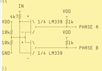
Next I setup an LM339 quad comparator to take a 0-3.3v signal and convert it into a discrete signal, but I fear that I've only succeeded in doing the same thing as a differential output of the counter.
I'm trying to take a phase waveform, 0-3.3v that should be a crossover at 1/2 VDD and turn it into a phase drive signal that gates the second pin of the phase drive so that when the waveform is above 1/2 VDD the companion drive pin is at ground, and when the waveform is below 1/2 VDD the opposite pin is grounded.
Here is a phase waveform for a microstepping drive:
I suspect that I've got a couple of problems:
I really have 2 issues to counter, understanding of how the PWM really works, and how to decode a single ended signal into a full H bridge drive.
LM339 Schematic:
I have included the code here:
Today I've been trying to turn the sin/cos phase outputs of the CTRA and CTRB into a 4 pin drive for the L293 on my PPDB.
My first idea was to use the counters in differential mode, but that quickly was proven an incorrect notion.
Next I setup an LM339 quad comparator to take a 0-3.3v signal and convert it into a discrete signal, but I fear that I've only succeeded in doing the same thing as a differential output of the counter.
I'm trying to take a phase waveform, 0-3.3v that should be a crossover at 1/2 VDD and turn it into a phase drive signal that gates the second pin of the phase drive so that when the waveform is above 1/2 VDD the companion drive pin is at ground, and when the waveform is below 1/2 VDD the opposite pin is grounded.
Here is a phase waveform for a microstepping drive:
I suspect that I've got a couple of problems:
- The sin/cos lookup may be inappropriate values and/or the period length of the counter is wrong
- The LM339 is generating differential outputs from 1 input instead of splitting the signal at 1/2 VDD
I really have 2 issues to counter, understanding of how the PWM really works, and how to decode a single ended signal into a full H bridge drive.
LM339 Schematic:
I have included the code here:
[FONT=courier new]''Demonstration of PWM version of NCO/PWM counter mode
CON

_clkmode = xtal1 + pll16x
_xinfreq = 5_000_000

VAR

long parameter

PUB go | x
  cognew(@entry, @parameter)
  repeat
    repeat x from 0 to 90 'linearly advance parameter from 0 to 100
      parameter := cos(x,90) << 16 + sin(x,90)          'a constant here locks to value x percent high
      waitcnt(1_000_000 + cnt)   'wait a little while before next update
    repeat x from 90 to 0 'linearly advance parameter from 0 to 100
      parameter := cos(x,90) << 16 + sin(x,90)          'a constant here locks to value x percent high
      waitcnt(1_000_000 + cnt)   'wait a little while before next update

PUB sin(degree, range) : s | c,z,angle
  angle := (degree*91)~>2  ' *22.75
  c := angle & $800
  z := angle & $1000
  if c
    angle := -angle
  angle |= $E000>>1
  angle <<= 1
  s := word[angle]
  if z
    s := -s
  return (s*range)~>16     ' return sin = -range..+range

PUB cos(degree,range)
  return sin(degree+90,range)

DAT
'assembly cog which updates the PWM cycle on APIN
'for audio PWM, fundamental freq which must be out of auditory range (period < 50?S)
        org

entry   mov dira, diraval              'set APIN to output
        mov ctra, ctraval              'establish counter A mode and APIN
        mov ctrb, ctrbval              'establish counter A mode and APIN
        mov frqa, #1                   'set counter to increment 1 each cycle
        mov frqb, #1                   'set counter to increment 1 each cycle

        mov time, cnt                  'record current time
        add time, period               'establish next period

:loop   rdlong value, par              'get an up to date pulse width
        mov a, value
        shl a, #16
        shr a, #16
        mov b, value
        shr b, #16

        waitcnt time, period           'wait until next period
        neg phsa, a                'back up phsa so that it
        neg phsb, b                'back up phsa so that it
        jmp #:loop                     'loop for next cycle

diraval long 11                      'APIN=0
ctraval long 101 << 26 + 1 << 9 + 0          'NCO/PWM APIN=0
ctrbval long 101 << 26 + 3 << 9 + 2          'NCO/PWM APIN=0
period  long 90                       '888kHz (1.25?S period) (_clkfreq / period)
time    res 1
value   res 1
a       res 1
b       res 1
[/FONT]
Comments
So you need a set of DAC's, then a current-comparison control loop.
By working in the current domain, variations in the motor inductance and Power rails, no longer matter.
http://www.allegromicro.com
has some examples.
For some ideas on how microstepping works, maybe have a look at this:
http://www.st.com/mcu/modules/Splatt_Forums/downloadtemp/AN1613_Microstepping%20with%20ST52.pdf
I believe you are correct in your statement.... provided you are not talking about high speed performance. For higher RPMs the number of microstepping states needs to be reduced, and for the very highest speed it must be eliminated. And then, to reach those higest speeds, volage and inductance do again matter.
But at lower than the highest performance, you are correct.
Cheers,
Peter (pjv)
But if you are OK with off the shelf IC.
http://www.mouser.com/Semiconductors/Power-Management-ICs/Motor-Motion-Ignition-Controllers-Drivers/_/N-41dumZscv7?Keyword=Microstepping&Ns=Pricing|0
I'm trying to generate the microstepping commutation sequence with a propeller. My understanding is that a PWM sine wave driving into an H-bridge driver will produce the commutation sequence.
What seems to be confusing, and perhaps a communication issue, is the statement that I have to work in the current domain. It's my understanding that a PWM sine wave *is* in the current when driving an H-bridge; after all, a PWM motor driver does the same thing, right?
I'm trying to turn a single ended signal into a 2 phase signal, meaning I want to generate a signal that outputs 1/2 VDD and up on one pin, and 1/2 VDD to ground on the other pin.
Since a stepper driver is 4 half-h bridges, I have 4 outputs to control, but with 2 counter outputs generating a sine wave. That's where the LM339 came in. When the sine wave is above 1/2 VDD It would gate 1 output, when below 1/2 VDD it would gate the other pin.
Am I going at this all wrong? I've read schematics of stepper drivers, read the app notes, and I want to try making the sequences with the propeller instead of buying a chip to do it. If I can do it right, I only need 1 L293/L297 per motor and can drive 7 motors per propeller. All of the stepper drive boards I've seen run about $15 per motor and are imported or use an imported chip.
Looking at the waveforms generated, their outputs are single ended and they are doing external gating. Instead of overlaying a square wave, they are gating the 2 pins of A and B phases.
I'm gonna go throw this on the scope/analyzer and check my waveforms again to see If I'm generating what I think I'm generating.
I was generating a single ended, single polar signal above. My output waveform was just like the ST32 app note above. I modified the counter output to generate a full 360 degree sin/cos waveform and ran it through my LM339 circuit. Downside is that the LM339 doesn't really do what I want. I'm getting a differential signal out of the LM339, not a gated signal; the low and high sides are overlapping.
So, I've got the waveform for 0-180 degrees, just like the ST52 app note, I've got to convert this 2 step waveform into a 4 step waveform, so that every 180 degrees I'm changing which output pin is GND.
I'm doing microstepping with a Propeller, to control an XY table for an electron microscope. For this I'm using the Pololu A4983 Stepper Motor Driver. The XY table is accurate to micro-meters.
I have it set to 16 micro-steps per step and it works fine, even at very high step rates. I have assembly code that provides ramping up and down. Without proper ramping you will have problems.
Let me know if you have any questions or need sample code.
Jim
I was able to do all of the commutation in software on the prop, 1 cog to drive a motor and 1 cog generating the sine/cos values it wants to send to the motor.
I don't need any external circuitry to generate the commutation, I just modified the driver code to detect the zero crossing point and update the counter output pins.
The code is far from optimized, but it's a proof of concept and I've got a small stepper motor sitting on my desk humming away quite nicely!
[FONT=courier new]''Demonstration of PWM version of NCO/PWM counter mode
CON

_clkmode = xtal1 + pll16x
_xinfreq = 5_000_000

VAR

long parameter
word cs,sn


PUB go | x,y,z

  cognew(@entry, @parameter)
  repeat
    repeat x from 0 to 359 step 15        '15 deg steps
           cs:= cos(x,256)      '+-8bit resolution
           sn:= sin(x,256)      '+-8bit resolution
      parameter := cs << 16 + sn          'pack cosine and sine
      'waitcnt(1000 + cnt)   'wait a little while before next update

PUB sin(degree, range) : s | c,z,angle
  angle := (degree*91)~>2  ' *22.75
  c := angle & $800
  z := angle & $1000
  if c
    angle := -angle
  angle |= $E000>>1
  angle <<= 1
  s := word[angle]
  if z
    s := -s
  return (s*range)~>16     ' return sin = -range..+range

PUB cos(degree,range)
  return sin(degree+90,range)

DAT
'assembly cog which updates the PWM cycle on APIN
'for audio PWM, fundamental freq which must be out of auditory range (period < 50?S)
        org

entry   mov dira, diraval              'set APIN to output
        mov ctra, ctraval              'establish counter A mode and APIN
        mov ctrb, ctrbval              'establish counter A mode and APIN
        mov frqa, #1                   'set counter to increment 1 each cycle
        mov frqb, #1                   'set counter to increment 1 each cycle

        mov time, cnt                  'record current time
        add time, period               'establish next period

:loop   rdlong value, par              'get an up to date pulse width
        mov a, value
        shl a, #16  'unpack a
        shr a, #16  'unpack a
        mov b, value
        shr b, #16  'unpack b

        cmp a, #$1FF wc     'test for 16bit signed value
if_nc    or a, mask         'sign extend
        cmp b, #$1FF wc     'test for 16bit signed value
if_nc    or b, mask         'sign extend

        cmps a, #0 wc      'wave change
        muxnc outa, #16    'status display
if_c    movs ctra, #2      'out pin 2
if_c    neg  a, a          'flip sign
if_nc   movs ctra, #0      'out pin 0

        cmps b, #0 wc      'wave change
        muxnc outa, #32    'status display
if_c    movs ctrb, #3      'out pin 3
if_c    neg  b, b          'flip sign
if_nc   movs ctrb, #1      'out pin 1

        neg phsa, a                'back up phsa
        neg phsb, b                'back up phsb
        waitcnt time, period           'wait until next period
        jmp #:loop                     'loop for next cycle

diraval long 1111                      'APIN=0
ctraval long 100 << 26 + 0          'NCO/PWM APIN=0
ctrbval long 100 << 26 + 1          'NCO/PWM APIN=0
period  long 256                       '800kHz (1.25?S period) (_clkfreq / period)
mask    long $FFFF0000
time    res 1
value   res 1
a       res 1
b       res 1[/FONT]