

PASM Gameduino drivers
 Martin Hodge
Posts: 1,246
Martin Hodge
Posts: 1,246
Several weeks ago, Alessandro De Luca posted his SPIN port of the Gameduino driver object for the Propeller. Being written in SPIN these drivers were, of course, many times slower than the Arduino. (To be expceted comparing an interpreted program to a compiled program.)
At that time I took it upon myself to begin the task of writing PASM Gameduino drivers. This is my first big project in 100% PASM and I have learned an immeasurable ammount about the Propeller and PASM in the process. There were many times in the process when I was frustrated with the Propeller. But once I got the hang of it, it's now become addictive. Most of the frustration came from having to un-learn habits and misconceptions picked up from previous architectures. I've spent a shamefully large amount of time on this, but it was hopefully worth it.
I welcome those seasoned PASM coders to have a look at GD_ASM and offer any suggestions. It is being released now in BETA form along with many of the Gameduino demos and utilities ported to SPIN. The PASM driver uses most of a cog (482 longs) but I'm confident that could be shaved down some.
This version is missing the "assets" method which is used to load some on-bard images and sounds from the Gameduino's Flash. That is next on the to do list.
There may be only one person interested in these drivers at present. But hopefully this should draw some attention to the Propeller in general and the Propeller ASC in specific.
Below are some video demos of the Propeller driving the Gameduino's various functions. These videos aren't really any different than the ones already on YouTube. They only serve to prove.
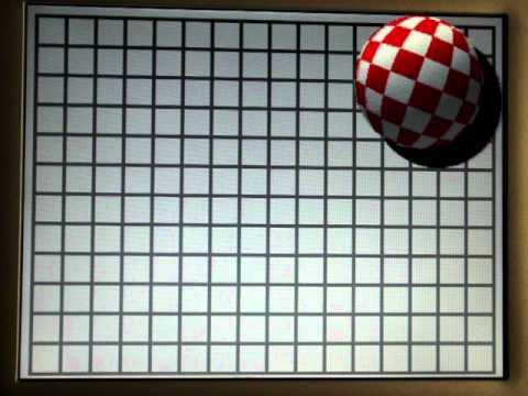
GD_BoingBall.spin: This is the famous bouncing ball demo. You can see it's a little slower than the Arduino version, but I'm confident that could be sped up with a little work on the demo code.
GD_scroll.spin: Demonstrates drawing randomly placed background elements and scrolling them through the screen while waiting on the video blanking. The occasional stutter you see in the video is from the camera and encoding. The output is liquid smooth.

GD_player.spin: Shows off the Propeller sending commands to the Gameduino's 64 audio voices. This demo has a small bug in that when cnt rolls over the playback skips/hangs. Since tempo is critical in this kind of app, a cog could be dedicated to keeping an accurate millis() count going. Then this tune could play for about 40 days before a glitch! (ears bleed)

GD_sprites256.spin: How about 256 sprites all on the screen at once? The Propeller barely breaks a sweat with this one.

GD_collision.spin: This one is my favorite. Parallax's awesome float32 object handles the complicated floating-point math (sin & cos) necessary to calculate trajectories and velocities of 40 sprites every frame. This one was also the most difficult to get working right. Take a look at that collide() function!

I added a function to GD_ASM specifically for the Propeller:
adr is the point in Gameduino RAM to begin reading
ptr is an address in hub RAM to begin copying to
count is how many bytes to copy
example: will copy all 256 sprite's collision bytes to an array (col[256]) in hub ram
10-10-2011
Gameduino.zip : v1.1
At that time I took it upon myself to begin the task of writing PASM Gameduino drivers. This is my first big project in 100% PASM and I have learned an immeasurable ammount about the Propeller and PASM in the process. There were many times in the process when I was frustrated with the Propeller. But once I got the hang of it, it's now become addictive. Most of the frustration came from having to un-learn habits and misconceptions picked up from previous architectures. I've spent a shamefully large amount of time on this, but it was hopefully worth it.
I welcome those seasoned PASM coders to have a look at GD_ASM and offer any suggestions. It is being released now in BETA form along with many of the Gameduino demos and utilities ported to SPIN. The PASM driver uses most of a cog (482 longs) but I'm confident that could be shaved down some.
This version is missing the "assets" method which is used to load some on-bard images and sounds from the Gameduino's Flash. That is next on the to do list.
There may be only one person interested in these drivers at present. But hopefully this should draw some attention to the Propeller in general and the Propeller ASC in specific.
Below are some video demos of the Propeller driving the Gameduino's various functions. These videos aren't really any different than the ones already on YouTube. They only serve to prove.
GD_BoingBall.spin: This is the famous bouncing ball demo. You can see it's a little slower than the Arduino version, but I'm confident that could be sped up with a little work on the demo code.
GD_scroll.spin: Demonstrates drawing randomly placed background elements and scrolling them through the screen while waiting on the video blanking. The occasional stutter you see in the video is from the camera and encoding. The output is liquid smooth.
GD_player.spin: Shows off the Propeller sending commands to the Gameduino's 64 audio voices. This demo has a small bug in that when cnt rolls over the playback skips/hangs. Since tempo is critical in this kind of app, a cog could be dedicated to keeping an accurate millis() count going. Then this tune could play for about 40 days before a glitch! (ears bleed)
GD_sprites256.spin: How about 256 sprites all on the screen at once? The Propeller barely breaks a sweat with this one.
GD_collision.spin: This one is my favorite. Parallax's awesome float32 object handles the complicated floating-point math (sin & cos) necessary to calculate trajectories and velocities of 40 sprites every frame. This one was also the most difficult to get working right. Take a look at that collide() function!
I added a function to GD_ASM specifically for the Propeller:
load_hub(adr, ptr, count)This method quickly copies a section of Gameduino's hardware RAM to an array you define in hub ram.
adr is the point in Gameduino RAM to begin reading
ptr is an address in hub RAM to begin copying to
count is how many bytes to copy
example: will copy all 256 sprite's collision bytes to an array (col[256]) in hub ram
GD.load_hub(GD#COLLISION, @coll, 256)example: will copy sprite 56's collision byte to the var "onesprite"
GD.load_hub(GD#COLLISION+56, @onesprite, 1)
10-10-2011
Gameduino.zip : v1.1
Comments
(From top to bottom) Gameduino, KVM adapter, Propeller ASC.
It was really nice to be able to use TV_Text for super fast, real time debugging on a separate TV screen!
Pictured here is the proper jumper config for using the ASC with the Gameduino:
(NOTE: pin 2 is only necessary in special cases)
Martin, I can't believe that you took the burden to port not only the driver, but also most of the demos!
I had my spin driver optimized, by removing as many function call levels as possible, and I got a noticeable speed improvement. But still waaay too slow compared to the original. Finally this does justice to both Gameduino and Propeller :thumb:
The main point that makes this interesting IMHO (vs using GD with Arduino), is that being the Propeller RAM based, and adding an SD card, then unlimited demos can be launched without beating up the flash too much.
I've tested this driver and works great, but I got sprites imagery corrupted. Since it's working on yours, I guess there's probably a slight variance in the minimum SPI clock pulse timing from board to board.
But it can be easily solved by moving the rising edge up one instruction, without speed penalty:
SHIFTIO_
              mov       inreg, #0               ' Clear inreg
              mov       sbits, #8               ' Load number of data bits
              mov       smask, #$80             ' Create mask

:loop         test      outreg, smask wc        ' Test MSB of DataValue
              muxc      outa, MOSI              ' Set DataBit HIGH or LOW
              test      MISO, ina     wc        ' Read Data Bit into 'C' flag
              rcl       inreg, #1               ' rotate "C" flag into return value
              [COLOR="blue"]or        outa, SCLK              ' Set ClockPin high         \_ swapped[/COLOR]
              [COLOR="blue"]shr       smask, #1               ' Prepare for next DataBit  /[/COLOR]
              andn      outa, SCLK              ' Set ClockPin low
              djnz      sbits, #:loop           ' Decrement sbits ; jump if not Zero

              andn      outa, MOSI              ' Leave MOSI LOW
SHIFTIO__ret  ret
Be sure to notify James Bowman about your work, I'm sure he'll be glad to hear about it.
Alessandro
James saw my announcement on twitter, so he knows.
Your data corruption may be caused by the current limiting resistors on the ASC board. Be sure you have solder jumpers on the bypass pads on the back for pins 9,11,12 and 13. I've looked at the SPI waveforms on my DSO and the Arduino is clocking data through at 8MHz. These drivers are running at somewhere between 1 and 2 MHz. So the Gameduino is not the weak link in this case. Let me know if you have the corruption with the jumpers in place. I'll swap those two lines though, good idea.
As for porting the demos, it was necessary to be sure the PASM driver was working properly. After the first one I found that the transition from C++ to SPIN wasn't that difficult.
Can you explain more about the hardware - what are the three boards and what is each board doing? Is this on a TV or VGA screen?
The middle board is the KVM adapter Link Here. I only included it for debugging.
The bottom board is of course the Propeller ASC.
On the other hand, I can't see a TV output so the prop still wins there.
For VGA this could do games and also form the framework for a very nice GUI. How does the video memory work - is there the video you can see, and then more ram to store sprites in?
You're right about the resistors, I completely forgot about them.
They're going to make slew rate lower.
Changing the duty cycle of the clock from 50ns/350ns to 100ns/300ns (with the same period) fixed the problem , that's what I was referring to.
The jumpers would work too, but with those lines swapped all the demos are running OK now.
Dr_Acula,
The Gameduino has cell based graphics, not bitmapped. The author has provided utilities to convert bitmaps and use them as backgrounds, much like the converter for PropGfx.
For a GUI like the one you've posted in the 256x224 video thread, I think that fully addressable frame buffer is preferable. So your efforts to use an external RAM are not wasted!
In my opinion what makes the Gameduino great is its focused design, and "clean room" implementation of retro graphics concepts. If the FPGA was bigger, or it had too many features... it would trigger the usual "You could as well implement the whole SOC in it!" type of argument.
No efforts are wasted. I believe someone, somewhere will always benefit from any effort to improve something.
VAR
  long  command

PUB null

  cognew(@entry, @command)
  waitcnt(8192 + cnt)

  dira[16..23]~~
  repeat
    outa[16..23] := plus($F0, 6)
    waitcnt(clkfreq/2 + cnt)
    outa[16..23] := mask(128,  0, 32,  0, 8, 0, 2, 0)
    waitcnt(clkfreq/2 + cnt)
    outa[16..23] := mask(  0, 64,  0, 16, 0, 4, 2, 1)
    waitcnt(clkfreq/2 + cnt)

PRI plus(a, b)

  command := @a | constant(([COLOR="orange"]$00F[/COLOR] << 9 | [COLOR="orange"]$012[/COLOR]) <- 16)    ' release version
[COLOR="silver"]' command := @a | address(@function, @function_ret)     '   debug version[/COLOR]
  repeat while command

PRI mask(a, b, c, d, e, f, g, h)

  command := @a | constant(([COLOR="blue"]$013[/COLOR] << 9 | [COLOR="blue"]$01C[/COLOR]) <- 16)    ' release version
[COLOR="silver"]' command := @a | address(@pattern, @pattern_ret)       '   debug version[/COLOR]
  repeat while command

PRI address(start, end)

  return (((start - @entry) >> 2) << 9 | (end - @entry) >> 2) <- 16

DAT             org     0

entry

:loop           rdlong  retaddr, par wz         ' wait for command (cmd:ret:addr:cmd = 7:9:14:2)
        if_z    jmp     #:loop

                movd    :arg, #arg0             ' get 8 arguments ; arg0 to arg7
                mov     t1, retaddr
                mov     t2, #8
:arg            rdlong  0-0, t1
                add     :arg, d0
                add     t1, #4
                djnz    t2, #:arg

' we now extract command and return location from t1 to keep retaddr intact
' t1 = cccccccr_rrrrrrrr_aaaaaaaa_aaaaaacc

                ror     t1, #16                 ' |
                movd    :call, t1               ' extract return address

                ror     t1, #9                  ' extract function entry point
:call           jmpret  0-0, t1                 ' call function

:done           wrlong  par, par                ' zero command to signify command complete
                jmp     #:loop                  ' fetch next command

' example function 1, adds the first two parameters

[COLOR="orange"]function[/COLOR]        add     arg0, arg1
                sub     retaddr, #4             ' result location (not 1st local variable)
                wrlong  arg0, retaddr
[COLOR="orange"]function_ret[/COLOR]    ret

' example function 2, ors all eight parameters

[COLOR="blue"]pattern[/COLOR]         or      arg0, arg1
                or      arg0, arg2
                or      arg0, arg3
                or      arg0, arg4
                or      arg0, arg5
                or      arg0, arg6
                or      arg0, arg7
                sub     retaddr, #4             ' result location (not 1st local variable)
                wrlong  arg0, retaddr
[COLOR="blue"]pattern_ret[/COLOR]     ret

' initialised data and/or presets

d0              long    |< 9

' uninitialised data and/or temporaries

t1              res     1
t2              res     1

arg0            res     1
arg1            res     1
arg2            res     1
arg3            res     1
arg4            res     1
arg5            res     1
arg6            res     1
arg7            res     1

                fit

CON
  retaddr = $1FF                                ' vscl, this cog isn't going to do video

DAT
Update: You can also get rid of masking outreg (& $FF). The SPI code only looks at the LSB anyway.I thought there must be a better way to do that. Also, arigatou for noticing the & $FF, fixed.
I don't see any reason not to speed up the SPI loop. However the cog spends most of it's time waiting on commands from SPIN. But if someone were to be using this object with another language it could be useful. (The Gameduino SPI interface tops out at 8MHz, btw.)
Sometimes you modify retaddr directly, in other places you copy it to a temporary variable instead (and then modify). Unless said function is called from somewhere else I don't see the need for two different access patterns.
Same (below) applies to the y-part. Seems to affect XSPRITE_ as well.
DAT
SPRITE_
'               ...

                shl     arg4, #4                ' SPI_Send((pal << 4) | (rot << 1) | ((x >> 8) & 1))
                mov     outreg, arg4
                shl     arg5, #1
[COLOR="orange"]                or      outreg, arg5
                shr     arg1, #8
                and     arg1, #1
                or      outreg, arg1
[/COLOR]                call    #SHIFTIO_


                shl     arg4, #4                ' SPI_Send((pal << 4) | (rot << 1) | ((x >> 8) & 1))
                mov     outreg, arg4
                shl     arg5, #1
[COLOR="blue"]                test    arg1, #|< 8 wc
                addx    outreg, arg5[/color]            ' outreg += arg5 + (carry := parity(arg1[8]))
                call    #SHIFTIO_
The second loop in ASCII_ may benefit from running $80..$1FC instead (removes the need for << 2). As for the first loop, the start has two hub window violations which are just wrong (and this adds up at a loop count of 768). Try this:ASCII_ ' arg0 = @font8x8 ; arg1 = @stretch mov t1, #0 ' t1 = i mov arg3, arg1 ' arg3 = @stretch mov arg2, arg0 ' arg2 = @font8x8 :loop rdbyte t2, arg2 ' t2 = b ror t2, #4 ' t2 = b >> 4, preserve lower 4 bits add t2, arg3 rdbyte t4, t2 ' t4 = h shr t2, #28 ' t2 = b & 15, restore preserved bits add t2, arg3 rdbyte t5, t2 ' t5 = lThe following 5 insn sequence can be shortened to 3 (ASCII_).' (at this point t2 and t3 are reusable) t1=i ; t4=h ; t5=l mov t2, #$20 ' m_wr($1000 + (" " << 4) + (i << 1) + 0, h) shl t2, #4 ' t2 = (" " << 4) mov t3, t1 shl t3, #1 ' t3 = (i << 1) add t2, t3 ' restructured ' m_wr($1000 + (" " << 4) + (i << 1) + 0, h) mov t2, #$20 << 3 ' t2 = (" " << 3) add t2, t1 ' t2 = (" " << 3) + i shl t2, #1 ' t2 = (" " << 4) + (i << 1)That addx thing is brilliant! 8 more longs.
(Also the last half of sprite and xsprite are virtually identical. I might try to reuse some code there.)
It took me a while to understand what you meant re $80 to $1FC for the loop but I got that one too. ASCII_ isn't used much but it did reclaim a long.
I used your jmpret scheme but instead of using a SPIN function during development I just added a big DAT section at the top. Speed at the cost of some longs in the hub.
DAT
        RGB_C           long (((@RGB_ - @entry) >> 2) << 9 | (@RGB__ret - @entry) >> 2) <- 16
        START_C         long (((@START_ - @entry) >> 2) << 9 | (@START__ret - @entry) >> 2) <- 16
                                         ... etc ...
PUB RGB(r,g,b) | rval
  command :=  @r | RGB_C
  repeat while command
  return rval

PUB _start(address)
  command := @address | START_C
  repeat while command
kuroneko, your suggestions have already saved 73 longs! It's so nice to have a second pair of eyes on the code.Hmmm... this is not entirely true. I knew it could emulate a partial bitmap area using sprites or redefined chars, but I didn't do the math.
It turns out that thanks to the huge number of sprites, it can pull very respectable bitmapped resolutions, like 320x192 in 4 colours. And still have 16 of them available, plus the entire 256 character set free for use as background, or in the area outside.
Here is a demo of 320x192 resolution (adapted from the original 256x256 by James Bowman).
The plot code is taken from chaotic attractors by JLS, found at http://jlswbs.blogspot.com
Martin (and Kuroneko), thanks for the new release.
Getting garbled display again... so I picked up the other ASC board wich had resistor bridged on SPI (only needed another on P9), and also tried both with 100MHz crystal:
The puzzling bit is that the 4 instruction per bit code doesn't work at 80MHz, yet the 5 instruction (inserting one nop for each bit) does at 100MHz! (5MHz bit rate in both cases).
Even more puzzling that the resistors doesn't seem to make much difference in this case.
Notice I also tested the original 1.0 code with bridges and, as you were suggesting, it works.
At this point if there is anyone else who has the hardware to test, I would wait for him to report back.
I think you and I are the only ones with this combo right now. Do you have an oscilloscope? This is what you should be seeing for the clock with the resistor bypassed (p13):
The resistors will make a big difference at these speeds. With them bypassed I'm getting a slope of ~50 V/us. With the resistors in-line I get this garbage:
Just for visual reference:
Yes it's a typo, I meant 6.25MHz
No I don't have a scope yet. It would be really handy now to find out about the difference of behaviour between your config and mine, even with resistor bridges installed.
Sorry if I keep hacking things 5 minutes after you release them, I'm just trying to find a compromise that could be useful for other ASC owners not willing to mod their boards.
I have another hack derived from the bitmap thing, hope you like it... Maybe I should translate this one the other direction (Prop to Arduino).
Also, have you noticed any real-world difference between Float32 and F32 in terms of speed? I didn't know it existed, but it looks interesting.
3rd edit:
If we're going to go with 4MHz instead of 5 then we might as well use a loop and save a bunch of longs.
SHIFTIO_      ' Thanks kuroneko
              mov       sbits, #8
              mov       phsb, outreg            ' idle NCO driving pin lb(MOSI)
              shl       phsb, #24               ' %tttttttt_00000000_00000000_00000000

:loop         test      MISO, ina wc            ' Read Data Bit into 'C' flag
              or        outa, SCLK              ' Set ClockPin high
              rcl       phsb, #1                ' rotate "C" flag into return value
              andn      outa, SCLK              ' Set ClockPin low
              djnz      sbits, #:loop

              mov       inreg, phsb             ' %00000000_00000000_00000000_rrrrrrrr
SHIFTIO__ret  ret
4th edit:
Just wondering what you're using to power the pair? USB, DC power supply, battery? Could you have a very noisy power source?
I can always make jumpers on the other board, if required. Until now I keept one untouched and made all hardware tests on the other.
Yesterday I did speed testing on F32 vs Float32. For single calls is 25% or more faster, difficult to say exactly.
Then I took the "rotation" function from the wireframe demo, which contains a well balanced real world population of 33 FP functions (12 MULs, 10 ADD/SUBs and 2 trigs), and tested running it with up to 20000 iterations, varying the argument and compensating for the SPIN overhead by subtracting a previously measured "idle" loop (calling an empty function, with same number of arguments and local vars).
The result is that as soon as you're above 10 calls (some hundred FP functions), the gain shows only small variation, and is consistently stable around 20%.
The other main feature of F32 is that it offers all the functions of Float32full using only one cog instead of two.
Tried it at 100MHz on the board with resistors (which should be the worst case) and seems rock solid! :thumb:
Unless you want to go like fsrw, and have multiple version ("GD_ASM_safe", "GD_ASM_fast", etc), I'd say let's use this 4MHz loop.
P.S. regarding power source, I've been running on USB power, but also tried a few different wall warts. Good idea, I can try an AA cell battery pack.
Considering the eons the COG spends waiting on SPIN I think the difference won't be noticeable. It does really bother me that you're having any troubles at all. It shouldn't be happening.
I agree. If the moment when you consider the library complete there is space left , it can be useful for helper functions for the graphic modes. At the moment I'm doing char drawing pixel by pixel, and if they called C64 pixel addressing a PITA... this is worst
btw maybe you noticed that I'm abusing the load_collision function (by passing it an address out of range), using it as a generic GD->HUB copy. Is there any special reason why you limited it to collision area?
Don't! It's all Arduino team's fault for designing a 5V device in the 3.3V (1.8V?) age!
Everything seems fine with 4MHz SPI, and it's useable with off the shelf ASC and Gameduino.
For fast moving signals with small chance of collision (i.e. 5V DRAM data bus), I've used limiting resistors as low as 220 ohms without problems, but I do realize that selling the ASC+ as a product require safety even with DC signals on pins, so the bump to 2k2 was in order.
P.S. I saw a product on adafruit.com using a TXB0108 level translator from TI, which seems to be auto-magically bidirectional... I didn't even knew it was possible. Dunno about the speed have to check the datasheet. Maybe it could be considered as a future option to replace resistors?
Originally I was going to include the two vblank waits in with it. But you're right there needs to be an inverse of the already existing copy function. I think I'll re-purpose it, now that you bring it up. Any other functions you can think of that would be nice?
Still, with both devices at 3.3v and no resistors it should be rock-solid.
I made prototypes with those very chips. There were two versions. One was open-drain and the other normal. The open drain version had it's outputs active and high by default. The regular version took an incredible amount of current from the external circuit to automatically switch it from output to input. Some of the shields I tried couldn't activate them.
Edit:
Okay I need an intervention :-o
Just thought of a simple BLiT function. But how could I test it?
That's exactly what I was going to suggest!
In the 80x24 text demo I'm using GD->HUB then HUB->GD in 128 chunks to scroll the screen (can't be more because of the screen arrangement, but maybe that can be revised later).
So a BLIT GD->GD can be dropped in, replacing the two:
assuming GD.Blit(dst, src, len), in "PRI scroll": from: GD.load_coll(dst - LOAD_OFFS, @tmpbuf, 128) GD.copy(dst, @tmpbuf, 128) to: GD.blit(dst, dst + 128, 128)GD.load_coll() is now GD.load_hub() and no longer pre-loads the collision ram. Otherwise it works exactly the same.
GD.blit(src, sstep, dst, dstep, count) is new. It does not touch the hub.
It will copy count bytes from src to dst in Gameduino RAM. sstep and dstep are deltas for the source and destination.
It isn't any faster, but it does save you having to allocate big buffers in the hub.
Text_80x24_Demo.zip
ok, thanks. I will try to figure if steps can be used to reduce the number of blits required.
I finally cracked the damn wireframe demo, it has been two days of swearing
This is another point where SPIN greatly limits the speed: if you watch the demo you can see that the FPS is almost not affected by distance (z coordinate), signifying that the J1 is doing its job, but we only get 10..30 fps depending on the object complexity, vs more than one hundred on the Arduino.
Also had a look at the timer rollover problem in GD_Player, it should be ok now.
I might revisit when the GCC thing is ready.