Shop OBEX P1 Docs P2 Docs Learn Events
Mysterious rotation sensor disk — Parallax Forums

Mysterious rotation sensor disk

Ron CzapalaRon Czapala Posts: 2,418
edited 2011-09-05 19:04 in General Discussion
I had an old Canon iP4000 inkjet printer that quit working.
Thinking that I might be able to scavange some stepper motors and other parts, I took it apart.

I was surprised to see that there were no steppers - just various regular DC permanent magnet motors and IR/photoresistor sensors to precisely move the paper and inkjet carriage.

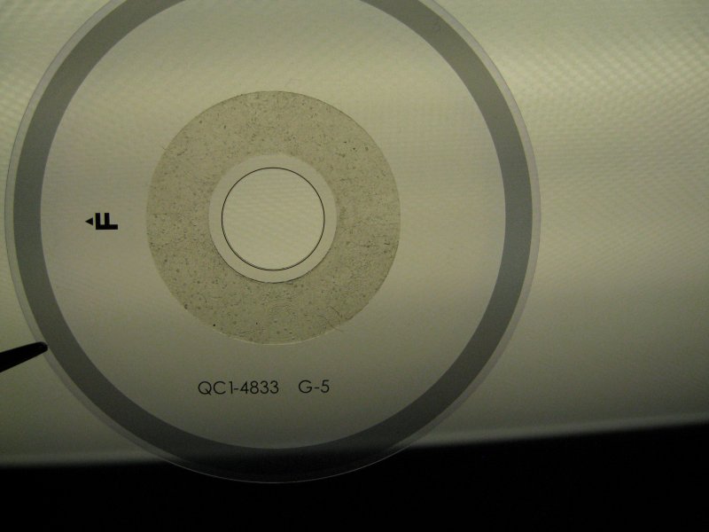
There are transparent disks glued to the gears and sensors positioned to monitor the track on the disks.

The strange part is that the track appears to be consistently the same darkness instead of alternate light and dark segments.

So how can this setup work???

attachment.php?attachmentid=84807


encoder disk.jpg
«1

Comments

  • Beau SchwabeBeau Schwabe Posts: 6,545
    edited 2011-09-03 20:00
    Is the grey area on the disk polarized? ... look at a crystal wine glass through it ... does it have a rainbow or prism effect... have any of the newer 3d glasses handy? not the red/blue, the ones that are polarized. Try looking through them and rotating your disc.


    EDIT: a Google search for that part number in the Photo indicates a 'FILM, TIMING SLIT DISK" ... there may be fine marks in the grey area that you can not see. It produces a very fine quadrature signal to the receiver.
  • Ron CzapalaRon Czapala Posts: 2,418
    edited 2011-09-03 20:20
    Is the grey area on the disk polarized? ... look at a crystal wine glass through it ... does it have a rainbow or prism effect... have any of the newer 3d glasses handy? not the red/blue, the ones that are polarized. Try looking through them and rotating your disc.


    EDIT: a Google search for that part number in the Photo indicates a 'FILM, TIMING SLIT DISK" ... there may be fine marks in the grey area that you can not see.

    I looked at using a bright six Sony IR video camcorder light and could not detect any variation.
    I thought maybe it had a dye that reacted to infrared light...

    I also looked a crystal wine glass thru it - couldn't see anything there.

    Curious...
  • RobotWorkshopRobotWorkshop Posts: 2,307
    edited 2011-09-03 20:25
    Most of the HP inkjet printers have similar encoder disks as well. For the carriage that goes back and forth with the ink cartridges there is usually a flat strip with the same markings that work as a quadrature encoder for that axis. Back in July 2008 I used one of these in a SERVO article on encoder matching. It is a nice example of a high resolution quadrature encoder. As I recall you only need to supply +v, ground, and then you can read each channel right off the sensor. If you run the sensor at 5V and connect it to a Propeller then I'd probably add a 2.7K or something similar in between the sensor and prop pins.

    Robert
  • Beau SchwabeBeau Schwabe Posts: 6,545
    edited 2011-09-03 20:27
    Check my update EDIT... When I google it, it appears to be a timing disk. I can find tons of places that are willing to sell it for as low as $1, but I can't find a data sheet on it.

    If you have a flat bed scanner, place it on the scanner and set it for the finest resolution... I bet then you can see the marks... maybe.
  • LawsonLawson Posts: 870
    edited 2011-09-03 20:34
    Any ordinary magnifying glass and a Digi-cam should help resolving the lines on that disk. The magnifying glass will let the camera focus closer than it otherwise would be able to. Otherwise, take two of the disks and set the outer gray strips roughly on top of each other. A course pattern of light and dark areas should form and move around as one disk is shifted relative to the other.

    Lawson
  • Ron CzapalaRon Czapala Posts: 2,418
    edited 2011-09-03 20:37
    Most of the HP inkjet printers have similar encoder disks as well. For the carriage that goes back and forth with the ink cartridges there is usually a flat strip with the same markings that work as a quadrature encoder for that axis. Back in July 2008 I used one of these in a SERVO article on encoder matching. It is a nice example of a high resolution quadrature encoder. As I recall you only need to supply +v, ground, and then you can read each channel right off the sensor. If you run the sensor at 5V and connect it to a Propeller then I'd probably add a 2.7K or something similar in between the sensor and prop pins.

    Robert

    I did not find a strip type encoder. The sensors only have three wires - ground, v+ for the emitter and the wire to the photo sensor. If it was a quadrature setup it would need two emitter-sensor pairs.

    It must really be high resolution! I need a microscope...
  • RobotWorkshopRobotWorkshop Posts: 2,307
    edited 2011-09-03 20:48
    Hello Ron,

    That disk looks just like the ones HP uses. Maybe Cannon is using something different. Do you have any pictures of the sensor that has the slot for this encoder disk? Maybe they were only using one channel. Very odd.

    Robert
  • kwinnkwinn Posts: 8,697
    edited 2011-09-03 20:58
    That is a high resolution encoder disk and a mask with the same density of lines is placed on front of the detector. When the disk lines are aligned with the mask lines the IR gets through the clear sections to the detector. When the disk lines are aligned with clear mask areas little or no IR gets through.

    Since the same circuitry that reads the pulses from the encoder also controls the motor it does not need a quadrature signal to tell it what direction the motor is going.
  • Ron CzapalaRon Czapala Posts: 2,418
    edited 2011-09-03 21:01
    Check my update EDIT... When I google it, it appears to be a timing disk. I can find tons of places that are willing to sell it for as low as $1, but I can't find a data sheet on it.

    If you have a flat bed scanner, place it on the scanner and set it for the finest resolution... I bet then you can see the marks... maybe.

    I was thinking that exact thing before I saw your reply.

    I set my scanner software to scan Positive Film and removed the back panel so the light would shine thru from the scanner cover.

    I had a hard time getting the scanner software to recognize the "film" but finally scanned it at 1600 dpi.

    You can see the lines now! Wow!!

    attachment.php?attachmentid=84808

    HiRes disk.jpg
    800 x 460 - 75K
  • Beau SchwabeBeau Schwabe Posts: 6,545
    edited 2011-09-03 22:48
    "When the disk lines are aligned with the mask lines the IR gets through the clear sections to the detector. When the disk lines are aligned with clear mask areas little or no IR gets through." - Exactly !! ... you can 'see' a similar effect when you have two perforated circuit boards and hold them up to the light to look at the 'holes' slightly twisting one board over the other.

    "Since the same circuitry that reads the pulses from the encoder also controls the motor it does not need a quadrature signal to tell it what direction the motor is going." - True, but the same sensor can have two detectors built into one unit and have a single 'mask' with two sections one section purposefully aligned 90 deg out of Phase. The result is a high precision quadrature output ... available when it's needed. depends on the application.
  • LoopyBytelooseLoopyByteloose Posts: 12,537
    edited 2011-09-03 23:09
    Several years ago, I managed to damage my HP inkjet printer by knocking it off a desk and decided to salvage parts. It did not have a disk, but had a strip of similar 'micro-lines' that positioned the carriage.

    It seems that a standard IR LED and sensor can handle such high resolution with the right firmware.
  • GadgetmanGadgetman Posts: 2,436
    edited 2011-09-04 03:37
    You should take a look at HPs 'Large Format' printers, such as the Designjet series of inkjet plotters. The sensor strip is a thin steel strip mounted behind the carriage. There's actually warnings in the manual about touching the strip as it's SHARP!
  • Heater.Heater. Posts: 21,230
    edited 2011-09-04 04:42
    I do believe that you guys are talking about Moir
  • kwinnkwinn Posts: 8,697
    edited 2011-09-04 09:45
    @Heater, it may be that they are using the encoder disk and detector mask to produce Moir
  • Beau SchwabeBeau Schwabe Posts: 6,545
    edited 2011-09-04 09:50
    Heater,

    "I do believe that you guys are talking about Moir
  • GordonMcCombGordonMcComb Posts: 3,366
    edited 2011-09-04 10:07
    Double-grated encoders don't have to use moire, though many do. Some use something called the Lau effect, and there are others (Talbot is an interesting alternative; I used a variation some 20 years ago to demonstrate a distance measuring technique that's been used in optical disc players more than a decade before that -- nothing is new, you know).

    Whatever the actual sensing these double-graters rely on diffraction and fringe effects to measure optical displacement. Because of the fineness of the optics, the encoder discs are virtually useless without their corresponding sensor. Good luck getting any information on the sensor.

    -- Gordon
  • Heater.Heater. Posts: 21,230
    edited 2011-09-04 11:34
    Ron,
    Have you tried shining a laser pointer through that grid? Just wondering if it's fine enough to get a diffraction pattern out of.
  • Ron CzapalaRon Czapala Posts: 2,418
    edited 2011-09-04 13:38
    I stuck the disk onto a hard drive spindle mounted in a block of wood.
    Then I made some small aluminum brackets and mounted the sensor next to it.
    I identified the IR emitter leads ans have it working but I haven't hooked up the sensor yet.

    The sensor has transparent windows on the top and bottom halves so you can see thru it.
    There is a 100 ohm resistor in series with the IR emitter and capacitor
    (which looks like a resistor with colored rings like a resistor) across the power and ground.

    The sensor has four connections GND, V+ and two others I assume to be the sensor output(s).

    More later...

    attachment.php?attachmentid=84814


    Encoder test.jpg


    module.jpg
    800 x 600 - 74K
    800 x 600 - 64K
  • RobotWorkshopRobotWorkshop Posts: 2,307
    edited 2011-09-04 13:55
    That sensor looks just like the ones I've pulled out the HP printers. There are four wires going there. I suspect that is a regular quadrature encoder.
  • Ron CzapalaRon Czapala Posts: 2,418
    edited 2011-09-04 14:01
    That sensor looks just like the ones I've pulled out the HP printers. There are four wires going there. I suspect that is a regular quadrature encoder.

    It might be - I was looking at some other sensors when I stated that there were only three wires - there were actually five optical sensors in the printer.
  • GordonMcCombGordonMcComb Posts: 3,366
    edited 2011-09-04 15:23
    With the (apparent) high resolution of the disc I'm thinking it's probably not a standard slit optical photocoupler. Diffractive sensors are capable of single-channel or quadrature outputs, just like regular photocouplers, but instead of detecting light-dark transitions they work by analyzing the differences caused by fringing.

    Look up polaroid diffractive encoder and you'll find numerous patents from the late 80s onward regarding this stuff.

    The industrial side of Canon makes/made a sensor of this type, but using a laser for its collimated beam. They are capable of over 75,000 transitions per revolution. Maybe there's a small picowatt laser in that thing, though more likely it's just an LED. In the high-end Canon encoders the output is a bi-phase sine wave -- a bit more work to interface than standard digital quadrature pulses.

    This may be neither here nor there, but as yours was a Canon printer it makes sense they're using Canon sensors.

    -- Gordon
  • Ron CzapalaRon Czapala Posts: 2,418
    edited 2011-09-04 16:19
    With the (apparent) high resolution of the disc I'm thinking it's probably not a standard slit optical photocoupler. Diffractive sensors are capable of single-channel or quadrature outputs, just like regular photocouplers, but instead of detecting light-dark transitions they work by analyzing the differences caused by fringing.

    Look up polaroid diffractive encoder and you'll find numerous patents from the late 80s onward regarding this stuff.

    The industrial side of Canon makes/made a sensor of this type, but using a laser for its collimated beam. They are capable of over 75,000 transitions per revolution. Maybe there's a small picowatt laser in that thing, though more likely it's just an LED. In the high-end Canon encoders the output is a bi-phase sine wave -- a bit more work to interface than standard digital quadrature pulses.

    This may be neither here nor there, but as yours was a Canon printer it makes sense they're using Canon sensors.

    -- Gordon

    Gordon,
    I think you may be right.

    I usually use my digital camera to view IR emitters since the camera sensor will pick up the IR frequencies, but I could actually see a red glow in the sensors with the naked eye - probably an LED.

    I don't think I'm going to pursue it now. I was mainly interested in disk's characteristics.

    I had no idea that such a high resolution was possible with these devices.

    The other two disks are lower resolution - the lines are clearly visible.
    In fact, they are marked 150 lpi - 150 lines-per-inch I assume...

    I think I was trying to use the wrong sensor with the high resolution disk. Two of the modules are identical so they probably match the low resolution disks.

    Thanks for everyone's input!
    - Ron
  • Ron CzapalaRon Czapala Posts: 2,418
    edited 2011-09-04 17:34
    Here is an oscilloscope image of the two output channels.
    I turned the disk slowly by hand and grabbed the image.

    It does look like a quadrature encoder

    attachment.php?attachmentid=84822

    oscilloscope 2.jpg
    556 x 545 - 56K
  • GordonMcCombGordonMcComb Posts: 3,366
    edited 2011-09-04 18:04
    Looks like the right sensor for the disc. At the resolution of the disc, if it were a standard slit sensor the output would be erratic at best, because many stripes would be visible through the slot. It's also clear you're seeing conditioned pulses, not signals straight off the detectors.

    If you can see a red glow it could be a near-IR laser -- they're not that expensive these days -- or it could be an LED with a very narrow output wavelength. The more coherent the light output the better. My money would be on a laser. They're actually cheaper in the long run.

    Though I can't imagine many robotic applications would benefit from this resolution you've got a pretty nice encoder there!

    -- Gordon
  • Ron CzapalaRon Czapala Posts: 2,418
    edited 2011-09-04 18:33
    Looks like the right sensor for the disc. At the resolution of the disc, if it were a standard slit sensor the output would be erratic at best, because many stripes would be visible through the slot. It's also clear you're seeing conditioned pulses, not signals straight off the detectors.

    If you can see a red glow it could be a near-IR laser -- they're not that expensive these days -- or it could be an LED with a very narrow output wavelength. The more coherent the light output the better. My money would be on a laser. They're actually cheaper in the long run.

    Though I can't imagine many robotic applications would benefit from this resolution you've got a pretty nice encoder there!

    -- Gordon

    I used a BS2 to count pulses on one channel over a 2 second interval and tried to do 1 revolution.

    It looks like approx 2500 pulses in 360 degrees!
  • $WMc%$WMc% Posts: 1,884
    edited 2011-09-04 19:12
    Nice find Ron
    '
    I have the need for a high resolution encoder.
    '
    Now I know where to find one.(I have a couple old printers laying around I kept for parts)
    '
    Thanks for the thread and info.
  • GordonMcCombGordonMcComb Posts: 3,366
    edited 2011-09-04 20:01
    It looks like approx 2500 pulses in 360 degrees!

    With quadrature that'll resolve to 10,000 cpr. Great for your inkjet printing bot!

    -- Gordon
  • kwinnkwinn Posts: 8,697
    edited 2011-09-05 15:14
    With quadrature that'll resolve to 10,000 cpr. Great for your inkjet printing bot!

    -- Gordon

    That may be a bit of overkill for a robot wheel sensor but sounds great for a precision cnc system.
  • Duane DegnDuane Degn Posts: 10,588
    edited 2011-09-05 15:31
    I was thinking it would be great to use with a laser and camera combo. You might be able to get more than just one distance point by moving the laser and keeping track of were the dot shows up on the camera. Or you could precisely move the camera laser combo.

    I'm going to start looking through some of my old printers for these. Thanks for posting the information.

    Duane
  • Mark_TMark_T Posts: 1,981
    edited 2011-09-05 16:19
    kwinn wrote: »
    @Heater, it may be that they are using the encoder disk and detector mask to produce Moir
Sign In or Register to comment.