

Time of Flight Laser Project
 Laser Developer
Posts: 140
Laser Developer
Posts: 140
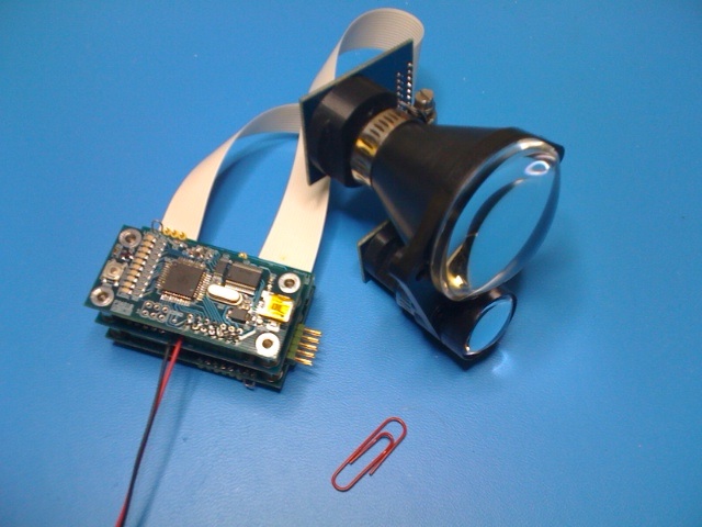
I have designed an IC that takes signals that are at the speed of light and slows them down to the speed of sound. This makes the building of a time-of-flight laser range finder much easier.
Inside the chip there are control subsystems that manage the power supply and firing of a high power, pulsed laser. Also, there is a gain and noise controller for an APD detector. Interfacing is done through a SPI bus and any small micro will easily be able to talk to the chip.
At the heart of the IC is a dual channel, time-expansion circuit. It takes the outgoing laser signal and the return signal and converts them into signals that are slow enough to measure using a timer on a microprocessor.
I am looking to work with someone who wants to make a serious (or not so serious) attempt at building a low cost rangefinder for robotics or other applications, as an educational project or as a commercial venture just so long as the end use is non-military. :thumb:
[Edit]
A big thank you to all who helped on this project. Without the support and enthusiasm of members of the Parallax forum it would never have been completed. For further information or if you want to get your hands on one of these please contact Prof_Braino.
Comments
I'm looking for people to partner with so that I can customize the configuration. For example, is it easier for designers to use CMOS or LVPECL inputs for the their analog signals? In my experience, LVPECL is actually easier because it is a balanced system that interfaces well with analog signals. In comparison, CMOS logic levels tend to be large and slow which is far from ideal for the speed needed in a laser rangefinder.
The chip design has configurable ports at this stage but I must select a final version before releasing it. Right now the chip has a CMOS input to detect the outgoing laser pulse which tends to be an electronic signal straight from the laser module, whilst it has an LVPECL input for the return signal that is optical before being converted through a trans-imedence front end.
It is these kind of details that can make the difference between a simple, well performing design and one that will never work. I am hoping that by solving the primary timing issues (the impossibly high speeds) that the rest of the subsystems will become more manageable to designers with average electronics skills.
Typically, signals with duration of 70ps get time expanded into signals with a duration of about 70us. That's a time expansion of one million times. At that time expansion it is easy to analyse and time signals that start out at the speed of light...
and a couple laser range finder http://www.holdpeak.com/Productshow.aspx?id=20420
but the second one is translated from Chinese.
Are any of these the one you are talking about? Or is there some reason you can't directly provide the link?
If there is some legal or other limitation, I would hesitate, but otherwise it would be interesting.
However, there are no restrictions on the new chip but as mentioned earlier, I'm not interested in military applications. Instead, I want to explore new markets and not stay in the industrial arena. This stuff is so cool that I would love to see it become mainstream - hobby and education type projects that may eventually lead to commercial products.
One of the key features of the new design is that it can be manufactured at a very low price. In small quantities the chip is less than $20. There is only a small amount of high frequency design needed outside the chip and this is more mechanical (short tracks with termination resistors) than complicated electronics. I think that one of the fun parts of doing this project would be creating a small pcb with a form-factor that fits one of the Parallax products. Then it would be a simple task for someone to make an "add-on" rangefinder for an existing project.
As a start though, there are only four basic elements to a TOF, laser range finder:-
1. The laser and its driver circuit.
2. The detector and its amplifiers.
3. A timing system.
4. An HMI or MMI interface.
Whilst each of these components has a few tricks to getting them to work, by far the most complicated is the timing system. By reducing this to a single chip, suddenly the whole design becomes much easier. For example, high power, pulsed lasers are now available from Osram in Germany with built-in driver circuits...
OK, your on.
Post the interfaces and operating parameter for the chip, and we (at least I) will start "attempt at building a low cost rangefinder for robotics or other applications"
So, does this trigger, then count at 30 gighertz till detection, then output the count?
No, there are no high speed counters at all. The fastest element runs at about 12MHz. I first encountered the idea of measuring using "lower than necessary" clocks during a university lecture (in the dark ages). The concept was called "random dither". What it meant was using two clocks at different frequencies and then making sure that events triggered by a master clock were never synchronized with results measured by a second clock. When used in timing applications it permitted averaging of the results to give a statistically better resolution than the "integer" counted by the second clock.
The equation for resolution is such that increasing the number of averages (shots fired) by a factor of four increased the measuring resolution by a factor of two. Therefore if your second clock has a frequency of 150 MHz then the resolution for a single shot is 1m (round trip). The resolution for four shots is 0.5m. The resolution for 100 shots is 10cm. And so on...
The first range finder that I designed used this technique. It was able to measure out to about 5000m with a resolution of 1cm (on a reflective target) and about 400m on a non-reflective target. The main problem was that I could only get the dithering to work properly at fairly high frequencies (>100MHz) which meant that the entire design was based on ECL (emitter coupled logic) and it just sucked power!
This is just one technique and without giving anything away, the new chip gets its inspiration from this concept but is much, much better...
Operates in slave mode.
CS - chip select, active high
SPI_Clock - normally low, data is clocked/written on the falling edge, read on the rising edge
SPI_Data_In - data from the microprocessor
SPI_Data_Out - data to the microprocessor
Data_Ready - goes high when a new result is ready
Data_ReadyN - inverse of Data_Ready, goes low when a new result is ready.
Questions:
Is a positive going or negative interrupt better for the Data_Ready signal?
Would a parallel interface be easier to use? 8bit/16bit?
Perhaps most important - do we have a name for this project?
The SPI interface for the prop already exists.
A parallel interface isn't really necessary, I think. Provided the result is just the range, a lot of samples could be sent each second serial.
Positive going or negative going doesn't matter, either is fine at your convenience.
My interface questions are along the lines of:
How to tell the device to configure and fire a sample? I.E. what is the SPI_Data_In from the microprocessor it will be expecting?
What is the format of the result? I.E. how many bytes and what do they represent (text character string, or four bytes representing a 32 bit number representing centimeters, etc)
How long from sample request to sample ready? How many samples per second can we request and recieve per second?
If the technic uses two clock at different frequencies, with the fastest 12 Mhz, we might be able to do the whole thing in software on the prop. Each cog has two counters that run at clock speed which is 80Mhz. We routinely generate different frequencies upto the clock speed. We are used to 12.5 ns as the minimum time for a single event. Which is about 12.5 feet at the speed of light, I guess? What you are suggesting is a different way of looking at it from I I think I have heard on these forums.
I will have to look up "random dither", I never heard of this before. I would also have to ask somebody about the trigger and detect mechanism, but there are LOTS of folks here that know the tricky stuff.
Both CMOS (MOSFET transistor) and LVPECL (bipolar transistor) based signaling is digital not analog....
"...CMOS logic levels tend to be large and slow..."
How about 2.5V CMOS logic that can do 625MHz. That's actually a 10 year old technology BTW... (see SGMII)
"The fastest element runs at about 12MHz..."
Take a look at the Xilinx FPGA. They can easily achieve 500MHz...
"I want to explore new markets..."
What markets exactly?
LVPECL is more than just a digital protocol. It's actually a hybrid that makes use of a linear region in the transition between logic low and logic high. In contrast, CMOS technology is digital in the strict sense that "midway" levels have to be avoided otherwise there is a current spike leading to an indeterminate result.
If we want to convert an analog signal into something that appears digital then the normal approach is to use a high speed comparator or AtoD convertor. Whilst you can get fast devices, remember that we need to achieve impossiby short delays through the convertor itself. In fact, anything that is longer than a few tens of picoseconds will mess up our design - more often because of the temperature drift than because of the delay itself which can be calibrated out.
In contrast, if we use a typical analog front end consisting of a fast transimpedence pre-amp followed by a differential post amp then we can bolt this straight onto our timing chip if we are using LVPECL logic at the interface. We do not need any other conversion technology.
The active voltage swing of 2,5V CMOS is "wide" in the sense that you don't know what the final result will be until the signal has gone all the way from one legal logic level to the other legal logic level. LVPECL is a totally different kind of animal. A "legal" logic swing can be as small as a few millivolts. This means that a very small analog swing is easily "digitized" without having to resort to massive amplification (which is very difficult at the bandwidths we are talking about).
As for the speed of CMOS, well, even 625MHz is just a bit too slow for our design. This will give us a resolution of 24cm which, whilst quite respectable, is an order of magnitude too big for a range finder that needs to work over short distances. For the same reason, the speed of the Xilinx FPGA limits us to 30cm resolution - still not enough.
Inevitably, you end up looking for timing "strategies" to compensate for shortfalls in straight clocking speed. There are many strategies out there, ranging from the "random dither" that I mentioned before to "gate delays" etched onto silicon. The thing that astonishes me is that they all work! The problem seems to be choosing the right strategy for a given requirement. For instance, do you need low power consumption, low cost, small size, noise immunity, long range, high resolution etc?
Selecting the right strategy boils down to understanding the impact that the strategy has on the rest of the circuit design. A strategy may be selected for its resolution but then you discover later in the design that there is a problem with the range. Engineering compromises are a fact of life. In that respect, my chip design is no different in that it compromises on certain performance characteristics in order to gain others.
As for potentially new markets, I have a list of over 50 that currently make use of laser range finders. The issue for me is getting to understand the market requirements. Intuition tells me that the small robotics business could do with some help. Is it a viable business opportunity? I don't know but it could be fun finding out.
1. SPI interface it is. Are there any limitations on the configuration? Some micros cannot handle all the permutations of clock edges and levels that are possible within the SPI definition.
2. The chip doesn't need to be told to measure (sample request). It measures continuously and the micro just has to ask for the results. The reason for this is to maintain "steady state" conditions within the power supplies of the rangefinder. Switching the laser or detector on or off creates spikes and transients that could interfere with the readings (you can switch it on and off but it takes a few seconds to reach stability again).
3. The SPI interface can be very simple or very complex depending on how much flexibility is needed in the final rangefinder design. What I would like to do is simplify it to the bare bones of a solution. The micro has to send some information to control registers inside the chip. These registers set things like the operating voltage of the laser, the gain of the detector (if it's an APD), the maximum measuring range and so on. At the moment the chip has no flash or EEROM memory so loading these registers has to be done at start up by the micro (I've got another design that does include non-volatile memory but it's much more expensive).
4. The configuration registers (data written by the micro) are all simple, 8 bit types with some of them being bitwise functional and others byte wide only. The results registers (data read by the micro) are a mix of 8 bit and 16 bit. Status type registers are 8 bits wide whilst results are 16 bits wide.
5. All data is in binary to keep the transmission strings as short as possible. A result would contain at least three elements. The first is a 16 bit integer representing the full range [span]. For a device measure 20m this could be something like 2000 (decimal) meaning that the resolution is set to 1cm. The second element is a 16 bit value representing the location of the return signal [return]. This could be 1543 (decimal) meaning that the return signal is at 15.43m. The final element is the zero point which is a measure of when the laser pulse left the rangefinder [zero]. This could be 157 meaning that there were delays in the firing and amplification circuits equating to 1.57m (10.5ns).
The actual distance is given by the simple equation: D = maximum_range [m/ft] x (return - zero) / span
In this example: D = 20m x (1543 - 157)/2000 = 13.86m
6. The measuring rate is one of the "engineering compromises" in the design. I would rather ask the question - what is the lowest and highest useable measuring rates that a small robot could take advantage of?
7. I like the idea of building a software solution but it probably isn't possible - there are things that I haven't yet told you. My first design was expensive and complex, not just because of the timing circuit but because of the receiver needed to provide clean, noise free, return signals. Think about it. If you make a timer that "stops" whenever it sees a signal then what if that signal is unintentional? Remember that a rangefinder has to locate weak return signals from distant objects. There will always be some noise buried in this return. It could be local noise from switch mode power supplies coupling into the pre-amps or it could be optical noise from background lighting. Getting rid of this noise is very difficult (impossible from a mathematical perspective).
The design of this new chip doesn't actually have a "real-time" timer that operates with start and stop signals. Instead, it creates a time expanded version of the real-time signal then uses a digital filter to remove the noise. The results that are presented to the SPI interface by the internal registers are actually measured by a 25kHz timer working on the time-expanded signal. That's why there are no high speed circuits in the design.
To make the design more fun I have provided an output from the chip that is the time expanded signal (actually there are two of them - the return signal and the zero signal). These outputs can be connected directly to a micro so that the micro can do the timing or store the signal in RAM for later analysis. Ah, I almost forgot - there are in fact two outputs for each signal channel - one is the filtered signal and the other is the unfiltered signal. That way you can make your own digital filter if you want. More importantly, looking at the unfiltered, time expanded signal (TEX_signal) on an oscilloscope helps to check the operating noise level of the whole system. Of course you can just use a cheap 20MHz scope to watch events that are happening at the speed of light...
"...longer than a few tens of picoseconds will mess up our design". You're looking at THz. The electrical circuit won't cut it here. Even your LVPECL. I think you should wait another 20 years or so... Good luck...
As for THz, I'd love to get my hands on some of that stuff! Perhaps the mistake that most engineers make is confusing frequency with time. This happens because we get trained to think in terms of oscillators as time bases so we are soon interchanging these ideas. Most people assume that the only way to measure time is with a frequency but this is not true.
A few years ago I was at MacDonald Observatory talking to the guys who do satellite and lunar ranging. The timing system that they are using is so good that they can measure to the moon with an accuracy of a centimeter or so. They use analog interpolation between the edges of a slow speed clock to get the required resolution. It's a kind of triangular wave that they can measure with an AtoD once the return is detected. There's no THz anywhere...
You seems to know a lot of cool things about a lot of cool stuff. This is getting interesting.
Low cost, short range is correct for hobbyist market, as we just wnat something in our hands to exeriemnt with. Actual professional appliactions may appreciate longer range and higher resolution, I can speak for those until there is something in my hands to give a point of reference.
I want one. I spend crazy amounts of money on toys to play with.
So let me see if I go a handle on this. You design triggers the laser, and detects the reflection, and sends back a time of flight, is that correct?
Cute. I suggest you avoid cute, engineers and cute do not go together. I HIGHLY recommend a descriptive name, something that includes something to the affect of "laser time of flight" since that is the thing you are talking about. Leave cute to marketing, I would also adivce them the same. You can ignore this advice, it may seem trivial; but if this ever becomes "not-trivial" it has already gone the wrong direction. I'll try not to mention this again, but its hard habit to break.
None known on the prop, if any are found it should trigger a re-examination of the project
Good to know, noted
Simple and cheap, thank you.
Noted
Noted.
Noted
Your choice. A single short (one measure) would be useable for some things. Anymore than a continuous stream to 115k baud (or so) would be too much for the micro to process. A typical application involving a moving robot might consider 30 readings per second more than enough, others could get by with 1 reading per second. My hope is you start with whatever is most convenient and cheapest, till we find real applications that need most one way or the other. My guess is 30 reading per second is enough, and 1 reading per second would be usable.
Good answer, this has been discussed at length and this is the finding from the previous discussions (if I understand the discussion so far).
I still can't get my head around this, so I'm just going to assume you are a genius or at least more experienced than me.
I like the way you think
That is correct.
There's a bit more circuitry needed to get power to the laser and bias the detector properly. Also, the micro still needs to set up the registers in the chip and do some calculations on the results to convert them into engineering units.
You have suggested that short range is adequate for hobbyists. In its most basic form, the minimum range of the chip is about 20m (60ft) and the maximum range is about 185m (560ft). Is this OK?
From second post:-
Project name: DS00VQ100 - I appreciate the advice. This is the technical name for the design anyway.
Thanks for the feedback. It looks like the basic design should be useful.
Speed and resolution at the minimum range of 20m are as follows:
Time expansion = +100k, Resolution = 0.06m, Update time = 0.0156sec = 64x per sec
Time expansion = +200k, Resolution = 0.03m, Update time = 0.0313sec = 32x per sec
Time expansion = +400k, Resolution = 0.015m, Update time = 0.0615sec = 16x per sec
Time expansion = +800k, Resolution = 0.0075m, Update time = 0.1250sec = 8x per sec
Time expansion = infinity, Resolution = infinity, Update time = forever
Time expansion = -800k, Resolution = -0.0075m, Update time = 0.1250sec = 8 x per sec
Time expansion = -400k, Resolution = -0.015m, Update time = 0.0615sec = 16x per sec
Time expansion = -200k, Resolution = -0.03m, Update time = 0.0313sec = 32x per sec
Time expansion = -100k, Resolution = -0.06m, Update time = 0.0156sec = 64x per sec
Any value of time expansion can be set using the internal registers - the table above just gives typical numbers.
The negative sign of the time expansion indicates time reversal. This means that later events are seen before earlier events. This is really useful for measuring through things like windows or long grass.
The way it works is this:
In forward time expansion the first signal is used to give the result, so the laser would probably see the glass of a window if it was in the way.
Using time reversal the first signal to be detected is the last thing that the laser light hits which will be a target outside the window.
You can switch between forward and reverse time expansion to help map complex environments.
If the concept of a time machine messes with your mind then you gonna blow a fuse when you see time reversal in action...
Thanks for your support. I recall a saying to the affect of "those that say it cannot be done should get out of the way of those doing it". I guess the challenge has been laid down, to a functioning prototype in less than 20 years.
I thought I had heard something like this, but this is part of the stuff I don't get. Is this the same technique you are using?
Should be no problem on the prop or many other micros
For less than 20m, ultrasonic can be used. PING goes to 3m, so there might be a blind spot unless other solutions are used (higher power, different frequency, more expensive transducer etc). If the part has range 20-156m, that is fine. I can find a use for it.
If it could register a signal for "any object detected less than 20m" that would be even better.
The pseudo random dithering is not "more practical" but is the only one that can be achieved...
"Most people assume that the only way to measure time is with a frequency but this is not true". It is true - Hz = 1/s.
"...kind of triangular wave". What's that? A sine wave?
"...most of the cost is in trying to stop the digital signals interfering with the analog signals". What are you talking about? It's a simple stuff, man... It was called 'complicated' many decades ago... Look at your cell phone (as one example)...
I think that one of the reasons why time-of-flight laser rangefinders haven't made it into the domain of the hobbyist is because of the complexity of some of the design techniques. Many of these techniques require considerable explanation and I don't claim to be a lecturer or teacher. The ideas that I am presenting do not apply to most other arenas of electronics. So I'm trying to describe them as they are used in existing laser rangefinders, not as they might be used elsewhere.
As an example, you have correctly stated that analog and digital circuits mix well in a cell phone. This is possible because the receiver is tuned and the data is transported on a carrier. Tuned circuits generally have very good noise performance and good rejection of interference. In contrast, the analog signals used in a time-of-flight laser rangefinder consist of very short pulses. These pulses have extremely wide bandwidths, a phenomenon that can be seen by Fourier analysis. This means that the analog signals exist over a very wide range of frequencies and, therefore, they are very susceptible to interference.
The time measurement question has to do with the difference between discrete and continuous measurement. Clocks and counters perform discrete measurements of time whereas most real phenomena only exhibit this effect at the quantum level. For most purposes time can be regarded as a continuous phenomenon and as such, it can be measured using continuous phenomena. The clock is a convenient invention but is not essential to the measurement of time.
Could this also be better stated as "the event registered as detection is the last reflection received"? I have a problem with the phase "later events are seen before earlier events"; sounds like special relativity and/or misleading.
The concept of a time machine does not bother me, if we are talking about my watch; and time expansion is ok, I have slowed down audio to hear the real voices of "Alvin and the Chipmunk". I am ok with time reversal as I have played records backwards to listen for satanic messages in Black Sabbath and Led Zepplin songs. But these terms have to used in the proper context, or risk giving the impression that you're just messing with us.
I'm getting the impression that when you say time expansion you are talking about that same technique as slowing down audio play back to pitch shift the frequencies down. Is this correct?