New board design, call for comments.
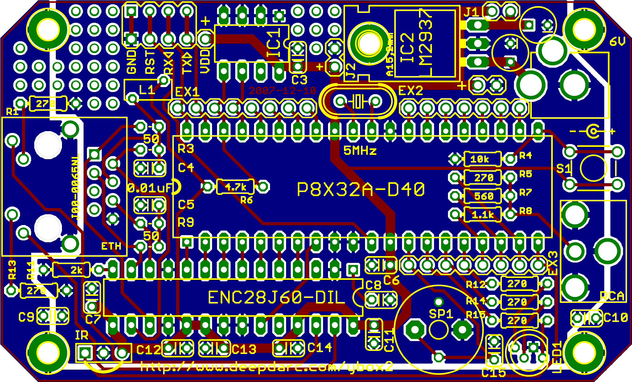
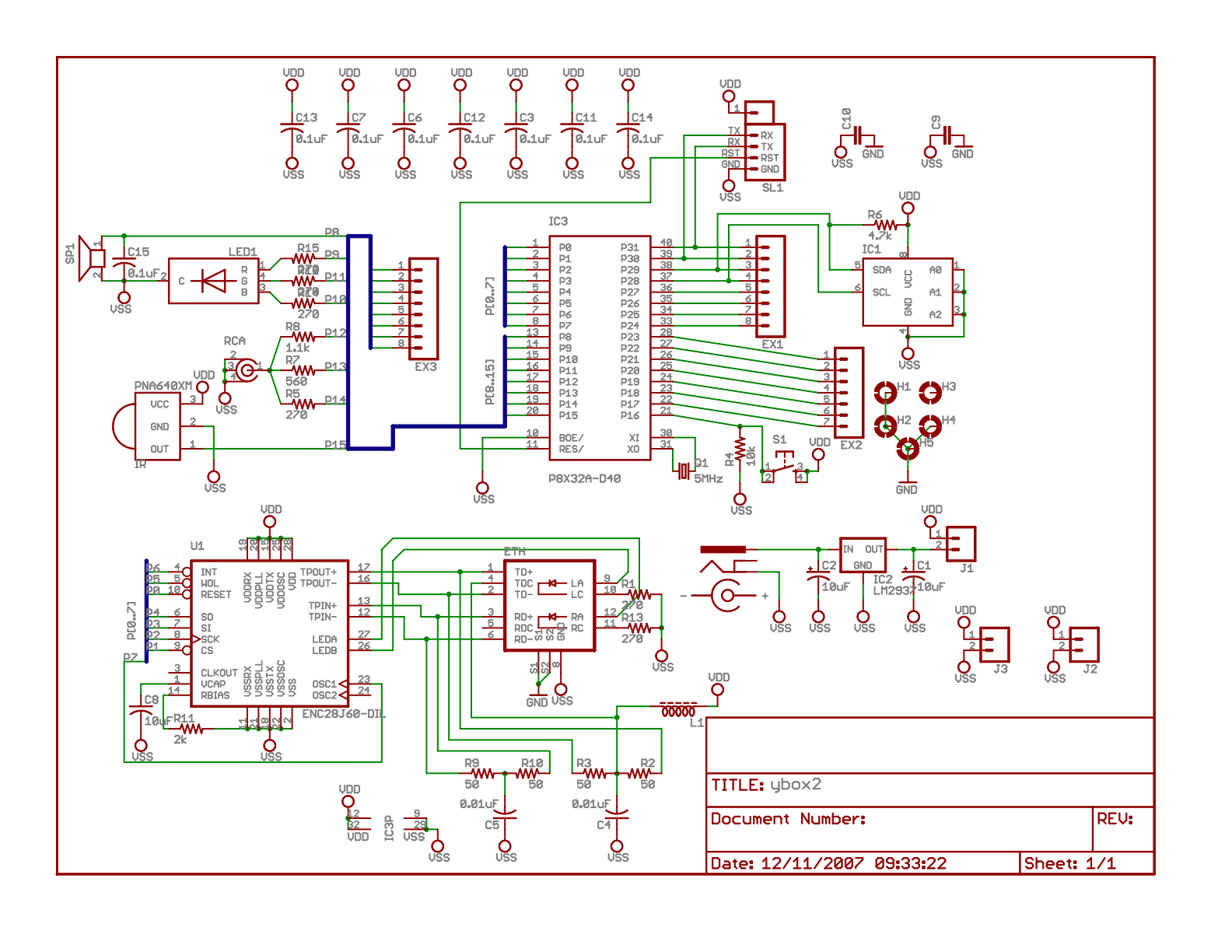
I've updated the ybox2 board design and schematic. Here is a summary of the changes:
With any luck, I hope to send this off to get fabbed in the next few days. I'll be posting the gerber and eagle files for everyone at that time. Let me know your thoughts, and thanks in advance!
▔▔▔▔▔▔▔▔▔▔▔▔▔▔▔▔▔▔▔▔▔▔▔▔
—
darco
www.deepdarc.com/
- I've separated the shielding (which includes the Altoids tin) from the logic ground. The bottom groundplane is now divided into two regions, one for GND and one for VSS. GND and VSS are connected with caps. (I have yet to determine what the proper values should be.) I'm hoping that this will make the device more robust.
- I've moved another resistor under the prop socket. Four in a row is probably the max I could fit under a 40-pin socket.
- I've updated the values for several caps.
- I've added a jumper (J1) which separates the output of the voltage regulator from VDD. This will make testing current flow more easy. Can easily be permanently closed by soldering a wire in place instead. It also allows for the inclusion of a PTC resettable fuse.
- Added headers for power connections, to complement the I/O headers. Should make it easier for tinkering.
- Was isolating the shielding from VSS a good idea? What are reasonable values for the caps connecting the two? Should I add more caps?
- Would it make sense to connect the shielding of the RCA jack to GND rather than VSS? (Currently connected to VSS) This would in theory prevent surges from moving thru the composite cable, but my inclination is to think that it would really hurt video quality.
- Originally, I was going to use the altoids tin as heat sink. However, the heat pipe (is that what it's called?) coming out of the voltage regulator is tied to VSS. Putting a screw thru it (connecting it to the altoids tin) would directly connect GND to VSS, defeating the purpose of separating the shielding in the first place. The whole thing doesn't pull a lot of current, so I guess a heat sink isn't strictly necessary. I considered just putting a large VSS pad under the regulator instead of a drill hole and then soldering the heat pipe directly to it. Would this be a good idea?
With any luck, I hope to send this off to get fabbed in the next few days. I'll be posting the gerber and eagle files for everyone at that time. Let me know your thoughts, and thanks in advance!
▔▔▔▔▔▔▔▔▔▔▔▔▔▔▔▔▔▔▔▔▔▔▔▔
—
darco
www.deepdarc.com/


Comments
The shield in a coaxial cable (unlike that of, say, a shielded twisted pair cable) is more than just a Faraday shield: it's also the signal return. So, yes, your RCA jack's "ground" lead does need to be connected to Vss.
-Phil
As for this board design, I'll be sending it off to Gold Phoenix tomorrow morning. I'll check this thread again before I put in the order just to make sure.
▔▔▔▔▔▔▔▔▔▔▔▔▔▔▔▔▔▔▔▔▔▔▔▔
—
darco
www.deepdarc.com/
the only thing to improve could be the voltage regulator. Since Ethernet devices are not really low power devices, i think it would be better to put a switched mode power supply (SMPS) on the board!
Try to use a LM2594 (also available in DIL8).
For development purposes i have done UMDL (Universal Microcontroller Development Lab) with a Propeller board.
see also: www.systech-gmbh.ch -> UMDL
Saluti Joerg
▔▔▔▔▔▔▔▔▔▔▔▔▔▔▔▔▔▔▔▔▔▔▔▔
—
darco
www.deepdarc.com/