

ybox-inspired networked set-top box (No XPort!)
 darco
Posts: 86
darco
Posts: 86
There is a special place in my heart for the original ybox, as it is what finally got me into tinkering with microcontrollers. However, the more I've learned, the more things I can find wrong with it's current design:
* It's expensive! That XPort is $51 in single quantities!
* The XPort shielding isn't properly grounded on the PCB, so if you have stray VDD wire touch the XPort, you just fried a $51 part!
* The PCB seems largely autorouted, with lots of vias and unnecessarily long traces for the video signal.
* Did I mention it was expensive?
So I've set out to make a better and less expensive networked set-top box in an altoids tin. Here is a list of what's different:
* Uses a Microchip ENC28J60 ethernet controller for network connectivity. The network stack will be implemented on the propeller.
* Uses a tri-color LED (instead of the single LED of the original) for more informative unit status at a glance. (also more bling)
* Has headers on almost all of the unused pins on the propeller, to facilitate tinkering.
* Adds an extra pin to the prop-plug header for VDD (next to the VSS pin).
* No vias, and the bottom copper is entirely groundplane. All signals are on the top copper layer, making it easier to see what is going on.
* At least $40 cheaper!
I wanted to add PoE support as well, but after researching that a bit it seems that to do it right would increase the complexity of the device considerably.
After studying Catweazle's ENC28J60 adaptor schematic, I'm not sure which pins on the ENC28J60 SPI need pull-ups. From looking at the datasheet, it seems like no pull-ups are necessary (and I've arranged my PCB layout accordingly for the moment). Can anyone provide any clarification?
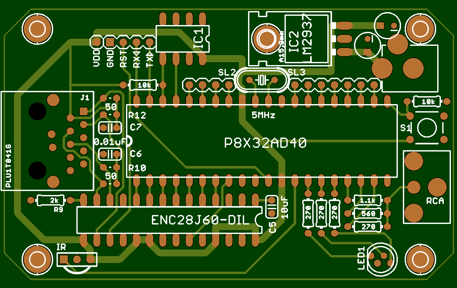
I'm almost done with the PCB layout, so I wanted to get some feedback from you guys on what I have so far. (See attachment). The bottom layer is all ground plane, so you should be easy enough to decipher from looking at the top. I would love to hear feedback and/or suggestions!
* It's expensive! That XPort is $51 in single quantities!
* The XPort shielding isn't properly grounded on the PCB, so if you have stray VDD wire touch the XPort, you just fried a $51 part!
* The PCB seems largely autorouted, with lots of vias and unnecessarily long traces for the video signal.
* Did I mention it was expensive?
So I've set out to make a better and less expensive networked set-top box in an altoids tin. Here is a list of what's different:
* Uses a Microchip ENC28J60 ethernet controller for network connectivity. The network stack will be implemented on the propeller.
* Uses a tri-color LED (instead of the single LED of the original) for more informative unit status at a glance. (also more bling)
* Has headers on almost all of the unused pins on the propeller, to facilitate tinkering.
* Adds an extra pin to the prop-plug header for VDD (next to the VSS pin).
* No vias, and the bottom copper is entirely groundplane. All signals are on the top copper layer, making it easier to see what is going on.
* At least $40 cheaper!
I wanted to add PoE support as well, but after researching that a bit it seems that to do it right would increase the complexity of the device considerably.
After studying Catweazle's ENC28J60 adaptor schematic, I'm not sure which pins on the ENC28J60 SPI need pull-ups. From looking at the datasheet, it seems like no pull-ups are necessary (and I've arranged my PCB layout accordingly for the moment). Can anyone provide any clarification?
I'm almost done with the PCB layout, so I wanted to get some feedback from you guys on what I have so far. (See attachment). The bottom layer is all ground plane, so you should be easy enough to decipher from looking at the top. I would love to hear feedback and/or suggestions!
1730 x 1093 - 108K
Comments
A better reference schematic can be found at: http://www.edtp.com/download/ft/framethrower_package.pdf . Only difference will be that there is no longer a WOL pin and the RBIAS resistor value is different on some of the silicon versions. (I believe B5 is something like 2k - 2.2k).
EDIT: You may want to reroute the ethernet signals farther away from the Propeller. It looks like you can remove your VDD loop and reroute the signals around. I generally try to keep higher voltage / noisy signals away from things like logic chips.
Harrison
Post Edited (Harrison.) : 10/18/2007 7:31:34 PM GMT
I'll post an image a little later after I tweak the layout a bit.
I'm thinking about adding a piezoelectric speaker. Are there any special considerations I need to take into account(like series resistor, current flow expectations, etc).
Anyone else have ideas for things to add to this board?
I normally connect piezo's straight from I/O to 0V on PICmicro's so wouldn't expect any problems with a Propeller. Hit a piezo and it will generate a fair belt of voltage, so maybe an R, but then you lose loudness.
BTW: when I mentioned the decoupling caps earlier, I meant 0.1uF, not 0.01uF.
You can click on it to see the larger version, or you can refer to the attachment. Any last thoughts or suggestions?
Does this use the same pin I/O as the demoboard/protoboard/SpinStudio for video,nic, etc?
It would be nice to see a standard start to emerge.. [noparse];)[/noparse] Either way sweet board! Planning to market them?
Oldbitcollector
▔▔▔▔▔▔▔▔▔▔▔▔▔▔▔▔▔▔▔▔▔▔▔▔
Buttons . . . check. Dials . . . check. Switches . . . check. Little colored lights . . . check.
— Calvin, of 'Calvin and Hobbes.
And, no, at this point I don't intend to sell it, primarily because I'm not sure who would be interested in buying it.
If there is demand however, it's something I'm willing to look into. [noparse]:)[/noparse]
Nice looking design!
▔▔▔▔▔▔▔▔▔▔▔▔▔▔▔▔▔▔▔▔▔▔▔▔
Timothy D. Swieter
tdswieter.com
One little spark of imagination is all it takes for an idea to explode
▔▔▔▔▔▔▔▔▔▔▔▔▔▔▔▔▔▔▔▔▔▔▔▔
A complex design is the sign of an inferior designer. - Jamie Hyneman, Myth Buster
Oldbitcollector
▔▔▔▔▔▔▔▔▔▔▔▔▔▔▔▔▔▔▔▔▔▔▔▔
Buttons . . . check. Dials . . . check. Switches . . . check. Little colored lights . . . check.
— Calvin, of 'Calvin and Hobbes.
And it all fits in an altoids tin.
The guys who made it never really took the server software much further than proof-of-concept stage, however. A tad disappointing, especially considering all of the fanfare they made leading up to it.
This board is an attempt by me to fix the things I didn't like about the original. Should be much cheaper to build, considerably more friendly to tinker with, and has more features to boot.
I can't wait to see what your ybox2 will be able to do. I am thinking about making a ybox-like device with my propeller proto board after I finish with my tcp stack drivers for the enc28j60. I really like the idea of having a dedicated tv channel at home for weather information.
Nice board. Did you capture a schematic for it? If so, please post it once things are finalized.
Also, I always wondered why there wasn't a keyboard connector on the original Ybox. A keyboard would allow chat and interactivity. An infrared or RF wireless keyboard would be really great for a set-top-box, but that's perhaps pushing a bit.
Last but not least, I would very much like to see an LED that would work like a message-waiting light. After all, you may be watching another channel instead of the Ybox2, the message-waiting light would prompt you to switch over to the Ybox2.
Thanks, David
P.S., I vote for the 40p-DIP package as well, especially with a socket.
Post Edited (Drone) : 10/23/2007 4:24:26 AM GMT
Are you using Eagle to generate your schematic and PCB layout? I like the blue looking version better.
▔▔▔▔▔▔▔▔▔▔▔▔▔▔▔▔▔▔▔▔▔▔▔▔
Timothy D. Swieter
tdswieter.com
One little spark of imagination is all it takes for an idea to explode
I just noticed one major issue with your board that I didn't notice before since the ground layer was hidden. The shield on the magjack should not be shared with your digital/logic ground plane. You should have two different ground planes, separated by as much as you can (I would say at least a few millimeters). Then connect the two separate grounds in one spot.
EDIT: Mentioned connecting the ground planes together in only one spot.
Harrison
Post Edited (Harrison.) : 10/23/2007 6:44:40 PM GMT
If not then in what kind of pool of them i have to buy and where to get that? Does MAC address have to be unique if device is inside a firewall ?
Are you planning on selling your devices? If so then you must buy an OUI from IEEE (standards.ieee.org/regauth/oui/index.shtml). It is really expensive (~$1650 USD) to get a OUI, but it does give you the ability to sell your devices without running into issues. You could also buy a bunch of old network cards and steal MAC addresses off those, but I am not sure about the legality of using another company's registered MAC addresses.
Luckily, if you plan on using the devices locally then you can use the OUI 10-00-00 which is the private OUI that can be used for testing and personal use. Commercial products should never use this so you shouldn't run into any problems as long as you ensure you don't accidentally reproduce your own MAC address assignments within your internal network.
IEEE specifies the 10-00-00 OUI as:
One last note, it is best to not fiddle around with random OUIs. The first byte's least significant nibble has special meaning when it comes to multicast/unicast universally administered/locally administered.
For the details of OUIs and such, take a look at the IEEE 802-2001 standard: ieeexplore.ieee.org/iel5/7732/21227/00984782.pdf?isnumber=&arnumber=984782
Harrison
However, I'm really confused as to why this is necessary, and why it is a "major issue". Could you explain? What kind of bad things does doing this avoid?
If you look at commercial NICs, you'll notice the shielding on the ethernet jacks are on a separate ground plane that is attached to the computer case. They also usually couple the shielded ground to the digital ground with a small cap.
Whichever path you choose the overall best bet is to separate the shields. The rest of the design relies on the internal design of the magjack. Sometimes the shields are just plain shields, which is ok to put on digital ground. Other times you should couple the shield via a small high voltage cap. If the magjack already has a cap in it then you can directly connect to ground.
EDIT: I misspelled plain...
Harrison
Post Edited (Harrison.) : 10/25/2007 1:34:04 AM GMT
EDIT: I think I have figured this part out...
Post Edited (darco) : 10/25/2007 3:58:26 PM GMT
Can anyone suggest which model of RJ-45 connector w/ integrated magnetics would be best to use for the pin assignments? I was using the LF1S022-34, but now I'm not sure how widely available this part would be to everyone. I'm looking into pulse's starjacks now... (MagJacks have a really large footprint, which make them unsuitable)
UPDATE: I've decided to go with the Pulse J00-0045, unless someone can give me a compelling reason to do otherwise. I will have to update the traces, as the pin assignments are a bit different from the LF1S022-34. I'll post pictures of the updated board when I have them. The J00-0045 has a cap built into it for surges, so I'll go ahead and connect it directly to the ground plane.
Post Edited (darco) : 10/25/2007 4:07:00 PM GMT
I know you are looking for layout comments here, but you also mentioned levels of interest and commercial value.
My x-wife has been all over me to get a couple of Bean's overlay boards so that we can track where "daughter dearest" has been in her car. I want the boards for other completely different reasons. Last night she wanted to know if we could track the suspect vehicle in real time. I'm thinking, "Sure... as soon as someone hooks up one of your altoids tins to a cell phone."
There is a real market for this kind of product... similar products are available, but with large entry prices and subscription fees.
The parents of America will worship you guys!!!
Rich
Unless I'm missing some key detail, tracking a vehicle is not a task which my board (or Bean's overlay board) would be able to handle without additional hardware at significant cost. You could, however, use the ybox2 (Or bean's overlay board) to display position information on a TV at home, assuming you have set up a way to get that information to the ybox2.
If you are trying to save money, then the most cost effective thing you could do is to buy one of the many pre-built position-logging tools out there. GeoChron is one such device, and costs ~$150.
I would go into more detail, but I'd rather not let this thread get too off-topic. If you would like to discuss a propeller-based vehicle tracking, which I'm sure quite a few people would be interested in discussing, please start a new thread.
This layout now uses a J00-0046 as the RJ45 connector, and has been re-routed accordingly. I've also isolated the shielding of the jack, as recommended.
I think this is pretty close to being finalized. Please let me know if you see anything wrong. (I won't be sending this off to get fabbed for a few weeks, so there is still time for corrections and improvements)
Important question: Should I be isolating the ground of the case (metal altoids tin) from my signal ground? At the moment, they are connected together, thru the plated screw holes. I can change this so that they fairly easily though... I'm new to this whole EE thing. [noparse]:)[/noparse]
Post Edited (darco) : 10/26/2007 6:05:56 PM GMT
i must confess, i'm missing the connection between tracking #1 daughter & video overlay (some sleep might cure this), but i happened to run across this item today, reasonably priced & designed for google earth - no subscription.
http://www.trackstick.com/
hh
sorry about the ot
hh
sorry about the ot but doesn't deserve a new thread.
HHays,
the overlay card supports Parallax's GPS solution. and can manage data logs.
I'm interested in seeing whether you hook up a couple of cards... sync them altogether and get some added bit depth by combining the analog signals.
There is also a potential synergy between darco's board and the overlay board from Hitt Consulting, which is on topic and which I thought should be mentioned.
Sorry for the confusion.
Rich
I would like to have it keep time at least relative time... check a time server or a web site displaying the time every few minutes.
display text from a web site (pretty sure it can do this)
display an image from a web site.
I'd prefer if it could do all of the above on one screen (output).
this can all be done while running some spin in the background?
▔▔▔▔▔▔▔▔▔▔▔▔▔▔▔▔▔▔▔▔▔▔▔▔
"A complex design is the sign of an inferior designer." - Jamie Hyneman, Myth Buster
DGSwaner