

Telescope observatory dome control.
 Christopher Erickson
Posts: 22
Christopher Erickson
Posts: 22
I am not sure if I am asking too much of a BS2 or not!
I have built·the Boe-Bot and worked through all of the projects in the book but I am certainly just beginning my learning curve with the BS2.
Essentially what I want to do is place a BS2 between a Meade telescope and the computer robotically controlling it.· The interface is RS-232, 9600 baud and software handshaking (if even that).· I want it's presence to be transparent and not require any hardware or software changes made to the scope or the computer controlling it, other than the serial cables.
I am hoping that the BS2 can transparently eavesdrop on the communications and at a predefined interval, insert a text string in the communications·going to the scope and then listen for the response, which will tell it the current Altitude and·Azimuth coordinates being pointed at by·the scope.· The telescope Azimuth data will tell the BS2 where the observatory dome Azimuth will need to be and it will drive some reversible gear head DC motors (via solid state relays) to keep the two Azimuths matched to each other whenever they differ by more than 5 degrees or so.· I will have a dome home position switch and an optical encoder on a rubber wheel that will tell the BS2 the current dome Azimuth.· The corrections will be·more frequent·when the telescope's Altitude is low and less frequent as the telescope Altitude increases.· That part·should be simple math and not a challenge.
When this project is done, I plan on making·it public domain.
I am interested in complying with any ASCOM4· standards that might be relevent.· ASCOM4 is an open source communications standard for small telescope observatories.· I don't know a lot about it yet myself.
The completed dome controller project·should work as a stand-alone dome controller, independent of the existence of an observatory·computer.· Simply connect it to the telescope's RS-232 interface and the dome motors and electronics.
Many other brands of GOTO telescopes support Meade's LX200 commands so the completed project should have wide appeal.
I will need to wait until any current computer command and the telescope response is complete before I insert an Alt-Az query to the scope and then buffer any computer commands until I have the scope's Alt-Az response.
The format of the Alt-Az query commands·are:
Command·· "#:GZ#"
··· Returns "DDD*MM#"
······· Gets the current telescope azimuth in degrees and minutes.
Command·· "#:GA#"
··· Returns "sDD*MM#"
······· Gets the current telescope altitude in degrees and minutes.
"*" character above is ASCI character 223 (degrees symbol)
"s" character represents the numerical sign (+ or -) symbol.
Quotes used above are not part of the actual·character string.
The·hash and colon·characters "#:" preceed all commands.
The hash character "#"·concludes all commands and replies.
Questions:
1. Can the BS2 keep up with two RS-232 interfaces at 9600 baud and manage to drive the dome around without any external serial data buffers?
2. Is there a better way to approach this project?
3. Am I missing anything?
4. Are there any simple RS-232 buffer chips out there that can be easily interfaced to the BS2, if needed?
If all goes well, I am hoping this is just the first of several BS2 applications·for a home telescope observatory.· Other projects might include dome shutter control, security, weather monitoring/rain detection/cloud detection, pneumatic snow removal·and more!
Any and all assistance and comments will be deeply appreciated!
-Christopher Erickson
▔▔▔▔▔▔▔▔▔▔▔▔▔▔▔▔▔▔▔▔▔▔▔▔
"My advice is free and worth every penny!"
-Christopher Erickson
Anchorage, Alaska
720 x 540 - 49K
Comments
▔▔▔▔▔▔▔▔▔▔▔▔▔▔▔▔▔▔▔▔▔▔▔▔
--DFaust
As the sensors on the mount, that is possible but most large mounts are oriented in RA-DEC and not Alt-Az. That means the axes are oriented to the rotation of the Earth and not the horizon, like the dome. Since the integral scope electronics are already programmed to sort all of that out and can be queried with simple ASCII commands via RS-232, additional encoders or whatever on the mount didn't seem reasonable.
Are there any standard all-in-one RS-232 driver/data buffer chips out there that interface to the BS2 painlessly?
Thanks for responding!
▔▔▔▔▔▔▔▔▔▔▔▔▔▔▔▔▔▔▔▔▔▔▔▔
"My advice is free and worth every penny!"
-Christopher Erickson
Anchorage, Alaska
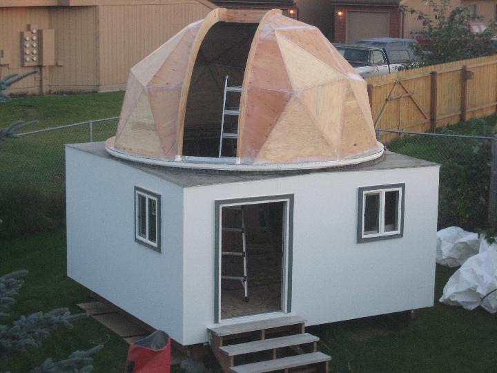
BTW: cool observatory, you building it?· Are the triangle panels of the dome standard features for observatories?·
▔▔▔▔▔▔▔▔▔▔▔▔▔▔▔▔▔▔▔▔▔▔▔▔
--DFaust
Post Edited (D Faust) : 10/18/2007 12:37:58 AM GMT
http://www.desertdomes.com
Here are a bunch of pics of my telescope observatory project:
http://24.237.160.4/files/Astronomy/MyObservatory/index.html
Or you can navigate to that spot from my web page:
http://data-plumber.com
Geodesic domes are just one of a zillion ways to build a home for a telescope. Some people build domes. Some round, some geodesic, some square. Some people build sheds with roll-off roofs. Some people build clamshells.
This has been one heck of a big project!
▔▔▔▔▔▔▔▔▔▔▔▔▔▔▔▔▔▔▔▔▔▔▔▔
"My advice is free and worth every penny!"
-Christopher Erickson
Anchorage, Alaska
▔▔▔▔▔▔▔▔▔▔▔▔▔▔▔▔▔▔▔▔▔▔▔▔
<FONT>Steve
What's the best thing to do in a lightning storm? "take a one iron out the bag and hold it straight up above your head, even God cant hit a one iron!"
Lee Travino after the second time being hit by lightning!
Everyone certainly knows more about the various Stamp capabilites than do I. However, are you talking about the Stamp having to take action every five seconds, or so, while listening in on the the commands from the PC? If so, my very, very limited understanding of such scenarios is that there isn't much going on and what's going on between the PC and the scope·happens fairly slowly. Is that incorrect?
If I am correct, then even a BS2 should handle what you need to do. However, take a look at the BS2px which is far faster than the BS2. (BS2px = 19,000 instructions per second, BS2 = 4,000 instructions per second.)
All Stamps are extremely limited in their RAM capacities. Plus, without coprocessor help, they have no ability to do anything other than integer math. And, their string handling capability is very limited. (Forget string handling ala VB!)
But, Stamps are fun and cheap. I encourage you to experiment. I would not cheap-shot the microcontroller by trying the BS2. I would start with the BS2px. And, you might think about networked Stamps . . . say, two. One listens--that sounds like the processor intensive part, if there is one at all--and the other inserts your instructions into the data stream when told to do so by the "listener."
Your project is extremely interesting. I hope you post your thoughts and results--should there be any--on this forum.
I will certainly not be offended by others with a more experienced view!
--Bill
▔▔▔▔▔▔▔▔▔▔▔▔▔▔▔▔▔▔▔▔▔▔▔▔
You are what you write.
I think the integer math issue is not a problem.· I plan to convert the telescope's Degrees and Minutes response to work everything in integer·1.4 "degree units" which gives me a·scale of·to 0-254 to represent the 0-360 degrees of azimuth, which I think is·more than enough accuracy·for good telescope tracking by the dome.· In fact, just view it as two simple counters.· One for the telescope azimuth and the other one for the dome azimuth.· Collect the scope azimuth every 30 seconds or so and move the dome if the difference between the two numbers is over a specified value, maybe like 5.· And then run the motors X seconds for every "degree unit" of difference.· Then collect the new dome azimuth from an external counter and mechanical encoder wheel, compare the two numbers and decide if more movement is required or to go back·to regularly sampling the telescope azimuth.
I think the only real challenge in·this project is the two serial interface issue and the possible need for·some modest data buffering on·the PC·side!
Thanks for your thoughts and rest assured that I will post any and all results as I begin physical experimentation.
-Chris
▔▔▔▔▔▔▔▔▔▔▔▔▔▔▔▔▔▔▔▔▔▔▔▔
"My advice is free and worth every penny!"
-Christopher Erickson
Anchorage, Alaska
The scope has a built-in GPS and the scope and the PC will both know the current time and Lat/Lon to ten decimal places.· The trick is to keep the dome aperture more or less centered in front of the center line of wherever the telescope optics are currently pointed.· That is, keeping the azimuth of the scope and the dome in synch with each other so the scope can always see the sky and not be blocked by the dome.· If the scope moves to point to a different part of the sky, the dome will soon follow.
I hope that helps to visualize what I am trying to accomplish!
▔▔▔▔▔▔▔▔▔▔▔▔▔▔▔▔▔▔▔▔▔▔▔▔
"My advice is free and worth every penny!"
-Christopher Erickson
Anchorage, Alaska
Both GPS's would always give the same Lat/Lon and time data. What I am trying to do is synch the Azimuth data of the dome with the current Azimuth (pointing direction) of the telescope. GPS's don't collect or present Azimuth data. A magnetic compass module is an Azimuth detecting device but it won't work accurately around the metal in the scope and the metal in the dome. Since the scope already knows its Azimuth to ten decimal places, all I need to do is ask the scope what it's current Azimuth is and then synch the dome Azimuth to it. I think the real trick is in transparently inserting into the serial data stream between the scope and the observatory PC.
▔▔▔▔▔▔▔▔▔▔▔▔▔▔▔▔▔▔▔▔▔▔▔▔
"My advice is free and worth every penny!"
-Christopher Erickson
Anchorage, Alaska
Command "#:GZ#"
Returns "DDD*MM#"
How long a time elapses between the command and the return? It takes a good fracton of a millisecond for the Stamp to turn around from sending a command until it is ready to receive. If the telescope is too fast, data will be lost or garbled and you have to get a faster Stamp or a serial buffer. But the telescope might delay enough, in which case it seems quite doable.
Another issue is that you want both the PC and the Stamp to be able to drive the same command line to the telescope. The two might fight one another. It is possible to make them share the line by a simple hack that involves a couple of diodes and a resistor, a mickey mouse OR gate.
▔▔▔▔▔▔▔▔▔▔▔▔▔▔▔▔▔▔▔▔▔▔▔▔
Tracy Allen
www.emesystems.com
As for the two serial outputs into a single input, I was hoping that having the BS2 in the middle, acting as a pass-through device with two serial ports.
▔▔▔▔▔▔▔▔▔▔▔▔▔▔▔▔▔▔▔▔▔▔▔▔
"My advice is free and worth every penny!"
-Christopher Erickson
Anchorage, Alaska
http://www.weasner.com/etx/autostar/as_schematic.html
▔▔▔▔▔▔▔▔▔▔▔▔▔▔▔▔▔▔▔▔▔▔▔▔
"My advice is free and worth every penny!"
-Christopher Erickson
Anchorage, Alaska
By the way - very nice project!
I have always been interested in astronomy and space, but unfortunately I live in a second floor apartment so my occasional observing is done with a pair of 7x50 binoculars.
▔▔▔▔▔▔▔▔▔▔▔▔▔▔▔▔▔▔▔▔▔▔▔▔
- Rick
Now, we need to know how the BS2 monitors the roof position. If it's supposed to be listening to a position encoder, that can be a problem -- it can't really get counts from the encoder AND get serial data at the same time -- so it may 'lose' the position of the dome, which is no good.
If the signals change slowly enough on the position encoder, though, you can use one of these for a 'real-time clock' to run a PBasic level 'multi-tasking' technique:
http://www.rhombus-tek.com/co-processors.html
The "simple multi-tasking" chip also has a buffered serial UART reciever in it, which kills two birds with one stone.
I had the opportunity to tour the Lowell Observatory in Flagstaff earlier this year. The dome of the old original building rolls around on old 1954 Ford truck tires with shiny hubcaps. Apparently they tried a number of schemes including floats before they settled on that.
▔▔▔▔▔▔▔▔▔▔▔▔▔▔▔▔▔▔▔▔▔▔▔▔
Tracy Allen
www.emesystems.com
▔▔▔▔▔▔▔▔▔▔▔▔▔▔▔▔▔▔▔▔▔▔▔▔
"My advice is free and worth every penny!"
-Christopher Erickson
Anchorage, Alaska
The position sensor will change REAL slowly (by BS2 standards).· I plan to drive the dome with high ratio DC gear head motors.· My goal is for the dome to take about a minute or more for a full 360 degree rotation.· This is for safety reasons as well as for power demand conservation.
That multi-tasking chip sounds real interesting and I will investigate that.· I think that a pair of BS2 compatible buffered UARTS is exactly what I am looking for.
▔▔▔▔▔▔▔▔▔▔▔▔▔▔▔▔▔▔▔▔▔▔▔▔
"My advice is free and worth every penny!"
-Christopher Erickson
Anchorage, Alaska
I think it will be way fun to come up with a bunch of different things for a bunch of different stamps to do in a robotic observatory.
▔▔▔▔▔▔▔▔▔▔▔▔▔▔▔▔▔▔▔▔▔▔▔▔
"My advice is free and worth every penny!"
-Christopher Erickson
Anchorage, Alaska
It's like your IR photosensor idea but avoids the potential interference with your CCD imaging, and may be easier than all the serial interfacing...
1. Lots of ferrus metal in the telescope, mount and observatory.· And much of it moves around.
2. A telescope using a GEM mount (German Equatorial Mount) has it axes lined up with the Earth's rotational axis, not the horizon.· This means there isn't any place to mount the sensor that will stay level as the scope moves around the sky.··Here is·a picture of a GEM telescope mount to hopefully help explain the challenge.
http://24.237.160.4/files/Astronomy/Mounts/AstroPhysics/slides/APSIDEBEST.html
3. Precision.· The front aperture of my telescope is 16" and the aperture of the 12' dome is 32".· It doesn't take much error before the dome begins obstructing the telescope's view of the sky.
▔▔▔▔▔▔▔▔▔▔▔▔▔▔▔▔▔▔▔▔▔▔▔▔
"My advice is free and worth every penny!"
-Christopher Erickson
Anchorage, Alaska
I'd be tempted to have one more 'zero' position for the dome. With only one 'zero', you'll have to rotate the dome 360 degrees (worst case) to find the zero position. With a zero degree and 180 degree limit switches, you only have to rotate 180 degrees -- 90 degrees on average.
▔▔▔▔▔▔▔▔▔▔▔▔▔▔▔▔▔▔▔▔▔▔▔▔
"My advice is free and worth every penny!"
-Christopher Erickson
Anchorage, Alaska
-Chris
▔▔▔▔▔▔▔▔▔▔▔▔▔▔▔▔▔▔▔▔▔▔▔▔
"My advice is free and worth every penny!"
-Christopher Erickson
Anchorage, Alaska
Will run two motors and can wait for a target to be reached (encoder count) and send a signal back when reached. I used it for a precision motion control project...
http://www.solutions-cubed.com/solutions cubed/MM1_2005.htm
I suggested the SX-48 because it has two hardware timers, one can be used for your encoder and the other for generating the motor pulses if needed.· I would also plan on adding two MAX232 type·chips for the serial ports, plus·needed support components.
SX-48 Proto Board:· http://www.parallax.com/Store/Microcontrollers/SXDevelopmentBoards/tabid/141/CategoryID/54/List/0/SortField/0/Level/a/ProductID/362/Default.aspx
SX-Key:· http://www.parallax.com/Store/Microcontrollers/SXTools/tabid/139/CategoryID/16/List/0/SortField/0/Level/a/ProductID/369/Default.aspx
Unfortunately, I don't have any direct experience with the SX,· but it's on my wish list!
I hope this helps.
In the posts above I see a tendency to over-engineer the whole thing. I hope nobody takes offense in that! I'm not an astronomer and I hope, I interpret the requirements right here.
You have the telescope pointed at an object in the sky and you want the slot of the dome to be more or less accurate centered to the scope?
I see there a different approach to the whole thing. I would not try to listen to the serial link, interpret that and then turn the dome to an absolute position...
How about that: have a laser pointer fixed to the rotating base of the telescope. Below the slot in your dome, you have three photo transistors: one right in the center, one left, one right of it.
When you start, the dome is in a undefined position to the scope and start to turn in one direction with full speed. It will reach one of the side sensors and your BS will switch the drive to slow motion until the the sensor in the center is reached... stop! From now on, as soon your telescope moves, the laser beam will leave the sensor in the center and hit the one left or right of it. This triggers again the motor to follow left or right until the center is triggered again and stops the drive.
With this you can reach always a defined relative position of the dome to the telescope.
If you want to do this project for the learning experience, how to deal with a serial port, how to count pulses etc. go for the way above...
If you want something working reliable with less parts, easy handling: KISSS (Keep It Simple, Square, Symetric)
Good luck and keep us posted about you progress!
EWo
I hope he sees your post. Your idea sounds very simple and extremely elegant.
--Bill
▔▔▔▔▔▔▔▔▔▔▔▔▔▔▔▔▔▔▔▔▔▔▔▔
You are what you write.