

Propeller & TLC5940 help needed
 Areal Person
Posts: 197
Areal Person
Posts: 197
Hi,
·
Could someone help me, I’m trying to hook up a TLC5940
to the Propeller. I’m really a newbe.
·
I’m using the wonderful spin code that BTX (Alberto) submitted. He has done some advanced work that’s really nice. Here’s the thread
http://forums.parallax.com/forums/default.aspx?f=25&m=164062&g=179076#m179076
·
·I’m just trying to get just one led working. I’ve read the datasheet & all the docs completely, but I’m a newbe. Here’s the setup I’ve got. I’ve not changed anything in the code.
·
‘······ P0 is the SOUT· out
'······ P1 is the SCLK· out
'······ P2 is the XLAT· out
'······ P3 is the BLANK out
'······ P5 is the GSCLK out
·
My VCC is the same as the propeller 3.3vdc
·
When I run the program and check the PIN’s with a volt meter here what I get.
----
VCC ·· ··········· 3.3v
SOUT· ··········· 2.0v
GSCLK··········· 0.2v
----
Everything else is 0v
·
I’m using a 10k resistor between the TLC’s GND and IREF to set max current
I’ve tried different sizes with no luck.
·
I’m trying to use OUT1 – OUT6, I have one LED on OUT6
·
If I can just get one LED started correctly, I think I can figure it out
·
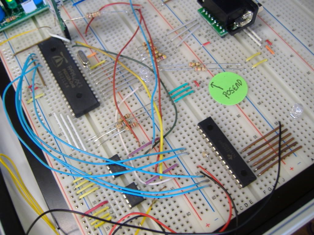
Below is a picture of my breadboard layout.
Please help, I’m lost. (Don’t worry about the other stuff I have hooked up or the GREEN STICKER , it’s not in the way, it’s just the standard Propeller board stuff)
·
Thanks for the help,
-Areal
·
·
·
·
·
▔▔▔▔▔▔▔▔▔▔▔▔▔▔▔▔▔▔▔▔▔▔▔▔
I have a tree growing out of my head, but
what do you expect ? I'm a programmer.
Post Edited (Areal Person) : 10/3/2007 3:18:34 PM GMT
Comments
propeller are skewed.
Is that stranded wire ?
Scott
The wire is just a light guage soild copper, it only needs to drive 1 LED.
All is 3.3v
Prop->P0 TO TLC->SOUT
Prop->P1 TO TLC->SCLK
Prop->P2 TO TLC->XLAT
Prop->P3 TO TLC->BLANK
Prop->P5 TO TLC->GSCLK
Thanks,
▔▔▔▔▔▔▔▔▔▔▔▔▔▔▔▔▔▔▔▔▔▔▔▔
I have a tree growing out of my head, but
what do you expect ? I'm a programmer.
I don't see why SOUT is at 2.0 V, unless data is being transmitted... Are you sure this pin is configured as an input to the Prop? Maybe disconnect it and see if it goes to 3.3v.
I wonder if you need pull up resistors on the input lines to the TLC5940 so that it doesn't go into some bad state while the propeller outputs are in a high impedance state...
I'm new at this, so I may be overlooking simple things also.
Actualy I've never hooked up any IC except the Propeller before, so I hope I can do this one.
It will be critical for me to continue in electronics.
I understand computers and programming well, I'm just green at electronics.
So I'm very greatfull for any help I can get.
Thanks,
-Areal
▔▔▔▔▔▔▔▔▔▔▔▔▔▔▔▔▔▔▔▔▔▔▔▔
I have a tree growing out of my head, but
what do you expect ? I'm a programmer.
My two cents: get a two eight led bars (or 16 leds) and connect all its output pins. That way you can figure out if you're getting any output at all. Your serial command width is either 92 or 192 bits wide, you might be missing on one led and hitting another. With just one LED in the circuit, you have to be as perfect as a finished project.
Also, I got a open wire tied to the BLANK pin, and it's acting like a motion detector,
if I move my hand close to it it dims the LED.
Thanks for all the help !
I'm thinking about starting a beginning Propeller website, is there one now ?
Hey, I still need help
-Areal
▔▔▔▔▔▔▔▔▔▔▔▔▔▔▔▔▔▔▔▔▔▔▔▔
I have a tree growing out of my head, but
what do you expect ? I'm a programmer.
I've made some notes (mostly for my own benefit) here:
http://www.rayslogic.com/propeller/propeller.htm
But, I haven't seen a "beginning Propeller website".
I can't get it to work using the software at
http://forums.parallax.com/forums/default.aspx?f=25&m=164062&g=179076#m179076
I don't understand why it's not working with the software ?
Any ideas ?
-Areal
▔▔▔▔▔▔▔▔▔▔▔▔▔▔▔▔▔▔▔▔▔▔▔▔
I have a tree growing out of my head, but
what do you expect ? I'm a programmer.
A main issue will be the electronics background, as with Areal here. It is very tricky to "learn" basic electronics in parallel to "microcontrolling".
One way out could be to use "microcontrolling" to learn electronics.
There are tons of "educational material" for the Stamp - just to be re-written for the Prop..
It's only one LED.
-Areal
▔▔▔▔▔▔▔▔▔▔▔▔▔▔▔▔▔▔▔▔▔▔▔▔
I have a tree growing out of my head, but
what do you expect ? I'm a programmer.
Not wanting to hijack the thread, but my "teacher" side screams out that the Propeller would be a perfect platform for learning basic
electronics. (packaged with suitable other components) It's ability to hold the interest of the student is one of it's strong points.
As said, the issue is material being written... I wish I had the electronics knowledge to write such a text...
Oldbitcollector
▔▔▔▔▔▔▔▔▔▔▔▔▔▔▔▔▔▔▔▔▔▔▔▔
Buttons . . . check. Dials . . . check. Switches . . . check. Little colored lights . . . check.
— Calvin, of 'Calvin and Hobbes.
If I wire it with one PWM/ENABLE Signal it works fine. It's when I try
to use the spin code, that's what I can't get to work, really there's only 3 pins that are needed
SCLK, SIN and XLAT.
The rising edge of SCLK shifts the data from the SIN pin to the internal register, in this case it's the GS register
because the software does not use DC (DOT Correction). After the data is clocked in the rising edge of XLAT
latches the data MSB first. I'm only using one chip so I don't care about SOUT.
I almost understand it, and I know nothing, someone who is good at this stuff should be able to
see through it clearly.
Thx,
-Areal
▔▔▔▔▔▔▔▔▔▔▔▔▔▔▔▔▔▔▔▔▔▔▔▔
I have a tree growing out of my head, but
what do you expect ? I'm a programmer.
Post Edited (Areal Person) : 10/4/2007 12:46:14 AM GMT
Give me some time to look for my documents about the TLC's and my code..I've just arrived home now...I need some time....
I was working all day out, and I must continue doing it "still here" (I mean not for your problem).
We're going to get the first job with the LED screen in the next sunday for the "MTV"....so...we have a lot of things to take care for that event !!!
Although sleep quiet...I will solve your problem...
▔▔▔▔▔▔▔▔▔▔▔▔▔▔▔▔▔▔▔▔▔▔▔▔
Regards.
Alberto.
The deeper meaning of my words should be: Using the microcontroller is just a "tool", so don't stress the importance of software tricks and whatever... The students will find that out for themselves when they need to...
Concentrate on electronics: "Today we want to build a transistor checker, determining the beta-factor of bipolar transistors and displaying some interesting characteristic curves on the TV..."
Well, check this for me please first....then let me know, if you have all this correct.
TLC5940
Pin 27 -> VPRG to· Gnd
Pin 22 -> Power Gnd
Pin 19 -> DCPRG to Gnd
Pin 20 -> R=1960 Ohm to Gnd ( For 20mA LED current )
Pin 21 -> Power Vcc 3.3 Volt
Pin 18 -> GSCLK······ (From Propeller)
Pin 23 -> BLANK······ (From Propeller)
Pin 24 -> XLAT······· ·(From Propeller)
Pin 17 -> SOUT to be connected to the "SIN pin" of the next TLC5940
Pin 25 -> SCLK······· (From Propeller)
Pin 26 -> SIN········· (From Propeller)
Then use the same pins, as my code use for·each of them....it must·work at once.
Let me know what happened please.
▔▔▔▔▔▔▔▔▔▔▔▔▔▔▔▔▔▔▔▔▔▔▔▔
Regards.
Alberto.
I wanted to say thank you very much for all your help to everyone !
I hope to have the Propeller turning on the lights of progress soon !
-Areal
▔▔▔▔▔▔▔▔▔▔▔▔▔▔▔▔▔▔▔▔▔▔▔▔
I have a tree growing out of my head, but
what do you expect ? I'm a programmer.
TLC datasheet indicates:· ILEDmax = (1.24Volt/R)*31.5·therefore to get 20mA maximun in the LEDs. you should use 1960 Ohm 1%. ( Digikey Part Number P1.96KCCT-ND·)
Like I used in my design.
But If you fell good using 19.5 mA...so use 2KOhm. I don't found any difference buying 1960 or 2K in SMD 0805 - 1%
▔▔▔▔▔▔▔▔▔▔▔▔▔▔▔▔▔▔▔▔▔▔▔▔
Regards.
Alberto.
And I wanted to say 2k2 The second "2" vanished somehow....
deSilva, I've a customer that his name is "Da Silva".....and he's·always my nightmare...can you figure out it ?? each time I see an answer from you...I need a plus in psychologist sessions. (and when he calls me by phone too many more)
▔▔▔▔▔▔▔▔▔▔▔▔▔▔▔▔▔▔▔▔▔▔▔▔
Regards.
Alberto.
Ok, I think were getting closer, but it's still not working yet. I wired all pins as you said.
What propeller pin does SIN go to ? is it prop->4 ?
Also, what should the LED's be doing ? (on always, flash one time etc. ?) I have 6 LED's, there on TLC->OUT1 - OUT6
Ha, Ha... If I hold the SIN wire between my fingers TLC->OUT1 - OUT6 flash on & off,
but what Prop pin does it go to ?
I will not change anything in the code until I get a handle on what it's doing, unless you say to.
Once I can get it to work, I will analyze the code.
Here's my wiring info
TLC27->VPRG··········=>··········· GND
TLC26->SIN··············=>··········· ???· - I DON’T KNOW WHERE THIS GOES.
TLC25->SCLK·········· =>··········· PROP->P1
TLC24->XLAT···········=>··········· PROP->P2
TLC23->BLANK········=>··········· PROP->P3
TLC22->GND ··········· =>··········· GND - 2.2KOHM RESISTOR
TLC21->VCC ··········· =>··········· 3.3V
TLC20->IREF ··········· =>··········· 2.2KOHM RESISTOR
TLC19->DCPRG········=>··········· GND
TLC18->GSCLK········=>··········· PROP->P5
TLC17->SOUT···········=>··········· NOT CONNECTED
·
TLCOUT1 – TLCOUT6··········· =>·· Connected to LED’s
Thank you,
Areal
▔▔▔▔▔▔▔▔▔▔▔▔▔▔▔▔▔▔▔▔▔▔▔▔
I have a tree growing out of my head, but
what do you expect ? I'm a programmer.
Post Edited (Areal Person) : 10/4/2007 4:56:52 PM GMT
TLC26->SIN Goes to Prop->P0
The software works great !!!!!!!!!!!
Thanks Alberto ! Your stuff is really cool !
My PCB's should be in from Hong Kong next week.
I will post plug & play instructions and resources for the community as soon as I get everything cleaned up !
Thanks,
-Areal
▔▔▔▔▔▔▔▔▔▔▔▔▔▔▔▔▔▔▔▔▔▔▔▔
I have a tree growing out of my head, but
what do you expect ? I'm a programmer.
I know I can cascade the TLC's by using the SIN/SOUT pin connections.
And I'm using 5 Propeller Pins to control up to 40 TLC's
Lets say I'm using 2 TLC's and have 32 LED's connected, (Thats 16 leds on TLC1 & 16 leds on TLC2)
Now lets say I want to turn on TLC1->OUT7 & TLC2->OUT7 with completly different data.
Generaly, How do I do it ?
How does the different data set get to the correct chip ? How does this addressing work ?
I can figure it out, but what is the correct way/technology needed for the TLC chip.
Thx,
-Areal
▔▔▔▔▔▔▔▔▔▔▔▔▔▔▔▔▔▔▔▔▔▔▔▔
I have a tree growing out of my head, but
what do you expect ? I'm a programmer.
This is TI's evaluation package (way too expensive for me) but has schematic on pages 15 & 16: http://focus.ti.com/lit/ug/slvu139/slvu139.pdf
more docs from TI's application notes: http://focus-webapps.ti.com/general/docs/sitesearch/searchsite.tsp?searchTerm=TLC5940&selectedTopic=206638686&numRecords=25
Post Edited (Fred Hawkins) : 10/4/2007 10:43:01 PM GMT
I had read these once before, but I just read them again, So... I'm I right in thinking that I can do whatever I want with the TLC's , right ?
E.G. -> In Serial Data Input Mode I fill all the TLC chip registers up via a passthrough datastream then I do the XLAT, like filling a glass with water ?
In Parallel Data Input Mode I need 1 extra pin per data input line per TLC, Or I need a custom switching circuit to route the data stream to the correct chip ?
Am I correct ?, which is the best way to do this, as I'm basicly going to make a VERY BIG LED TV. The data is always going to be VERY esoteric.
I don't think I can use I2C or SPI ? Right ? (Not that I ever have before). I'm gonna to need to build custom routing system for the TLC's.
unless I just always fill them all up anytime I need to change any single led ? Right ?
Thx,
-Areal
▔▔▔▔▔▔▔▔▔▔▔▔▔▔▔▔▔▔▔▔▔▔▔▔
I have a tree growing out of my head, but
what do you expect ? I'm a programmer.
Post Edited (Areal Person) : 10/4/2007 11:45:53 PM GMT
But it looked to me that your constraint is a pair of equations (one was 4096 * f_update, another was I think 193 * n * f_update) that determine just how fast your serial data has to go. TI says your maximum freq is 30MHZ for both equations. Flicker goes away with an update rate of about 80hz, but that depends upon who's looking I suppose.
But that's all moot, your limit will be how fast you push meaningful image data from the prop to your array. The data seems to be an command packet of 92 bits followed by a packet of brightness information in 193 bits, sent in turn to each TLC along the same serial line. I didn't catch how they figure out which one takes the data and why the rest sit on their hands.
And how much you want to spend. 40 of these only light up 640 LED's; divided into RGB that's only 213 pixels. (Now you see why Alberto used a dozen props or so)