Shop OBEX P1 Docs P2 Docs Learn Events
Tiny Keyboard on the cheap for the prop — Parallax Forums

Tiny Keyboard on the cheap for the prop

sharpiesharpie Posts: 150
edited 2007-06-02 01:01 in Propeller 1
Since I've seen so much talk about small keyboards around here, I decided I'll share an idea I had YEARS ago when playing with the basic stamp... It used RCTime.
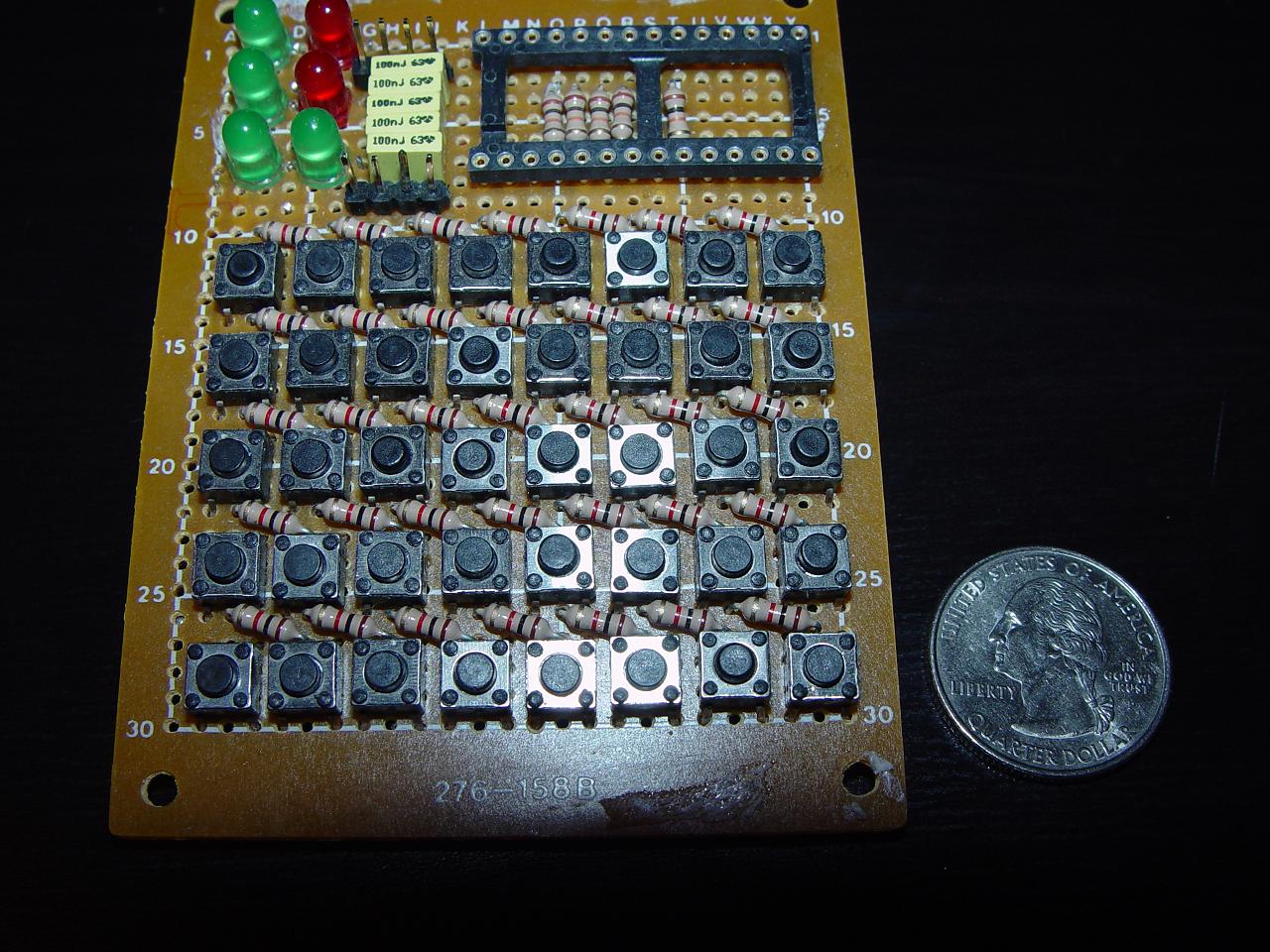
It's fairly simple but works perfectly.· 40 keys, and you can assign them for whatever functions you want =)· You can get all the parts from mouser, etc...
The keyboard needs only to measure a little over two inches tall and 3 inches wide...or so..

If anyone is interested I can post a schematic and some part numbers...
1280 x 960 - 223K
«1

Comments

  • sharpiesharpie Posts: 150
    edited 2007-05-20 09:15
    I should mention this board wasn't built for the prop... and was made a LONG time ago... I know it's ugly.
  • Graham StablerGraham Stabler Posts: 2,507
    edited 2007-05-20 10:34
    I think its beautiful and I'd love to hear how it works.

    Graham
  • BeanBean Posts: 8,129
    edited 2007-05-20 13:04
    I'd like to see a schematic too.
    Looks nice.

    Bean.

    ▔▔▔▔▔▔▔▔▔▔▔▔▔▔▔▔▔▔▔▔▔▔▔▔
    “The United States is a nation of laws -· poorly written and randomly enforced.” - Frank Zappa

    - - - - - - - - - - - - - - - - - - - - - - - - - - - - - - -
    www.hittconsulting.com
    ·
  • boeboyboeboy Posts: 301
    edited 2007-05-20 15:25
    I don't think it is ugly it's a work of art. But a schematic would be nice.

    ▔▔▔▔▔▔▔▔▔▔▔▔▔▔▔▔▔▔▔▔▔▔▔▔
    lets see what this does... KA BOOM (note to self do not cross red and black)
  • Graham StablerGraham Stabler Posts: 2,507
    edited 2007-05-20 15:29
    Ah ha, I know how it works I think.

    There are 5 rows of eight, each row has eight resistors, you use RCtime to measure the resistance and work out the buttons pressed.

    But does it allow you multiple buttons on the same line? If it was like an R2R ladder it could I guess.

    Graham
  • PaulPaul Posts: 263
    edited 2007-05-20 17:43
    Shouldn't this be moved to Sandbox as its not specific to the Propeller?
  • Graham StablerGraham Stabler Posts: 2,507
    edited 2007-05-20 20:01
    No because it follows on from earlier discussions on suitable interfacing for the propeller and in the sandbox we wouldn't have seen it. The propeller has such simple graphical interfacing it is in special need of other human user interfaces such as this especially for portable devices.

    Graham
  • rjo_rjo_ Posts: 1,825
    edited 2007-05-20 20:46
    Graham... I saw your note about the $5 media player... and followed some of the links... have you concluded that it is doable as a display for the prop?

    Sharpie... I think I've made it clear that I'm not an engineer, but to my eyes... your keyboard is a work of art.

    Paul: I agree with Graham. I think mini-micro-nano-keyboards are appropriate for this forum, because one of the stated goals is for an Altoids compliant Prop design... and that requires an Altoids compliant keyboard... but it is too bad that the same posts can't show up in both the sandbox and in the Prop forum. Something else for Parallax to consider after the next round of hardware.

    Sharpie:

    I did some rough photogrammetry on your Keyboard and it is roughly Altoids compliant... a little shaving here and a little scrunching there and presto, you have the first Altoids compliant Propeller keyboard!!!

    But will it float?

    I was wondering whether your board couldn't be modified slightly to become a keyboard controller...

    so that an inflatable keyboard could "talk" to the keys on your board?

    Chip mentioned that he wanted the engineers to be thinking of the Prop while they are in the restroom...

    I would you like the engineers to be playing with the Prop in the tub!!!

    If we are going to have an Altoids compliant Prop... we should be able to take it to the beach[noparse]:)[/noparse]


    Rich
  • Robert KubichekRobert Kubichek Posts: 343
    edited 2007-05-20 21:10
    It does look like rctime, 5 rows of 8 resistors.
    So if fast enough, it can read 5 keys pushed at a time...

    NICE!! jumpin.gif

    Bob scool.gif

    Post Edited (Robert Kubichek) : 5/20/2007 9:21:33 PM GMT
  • PropabilityPropability Posts: 142
    edited 2007-05-20 22:50
    ·I found these type of keypads at the local surplus for $1.98 but they have 1 common and 12 outs (or ins if you like) which would chew up I/O fast.

    I interweaved 12 common value resistors thru the I/O holes to form a voltage divider circuit that can be read with a A/D circuit. Nothing fancy but it works.

    Pete
    2080 x 1368 - 114K
    2080 x 1368 - 107K
  • Graham StablerGraham Stabler Posts: 2,507
    edited 2007-05-20 22:52
    I guess the fact he said it uses RCtime in his first post might have been a clue too.

    If the 8 keys in each row were binary coded you could read 40 key pushes at once [noparse]:)[/noparse]

    Graham
  • sharpiesharpie Posts: 150
    edited 2007-05-20 22:54
    You guys are pretty much on the mark about the rctime reading the resistors.. I have with some luck been able to read multiple key presses..· Maybe with some tweaking, etc. it would be pretty reliable too..· I never got to spend the time I wanted on this project, originally the keyboard was actually smaller and mounted on my wrist..· I will get to it and post a schematic and parts numbers..· The buttons are cheap from mouser, and they have way more styles now than when I built this, including some with removable key caps. I do think it should be fairly easy to fit it into an Altoids tin.·

    I also have included a shot of the back of the board..· Should provide some more insight...· Hope you like.
    1280 x 960 - 325K
  • sharpiesharpie Posts: 150
    edited 2007-05-20 23:22
    You know, and for what it's worth.. anyone with a dead blackberry laying around... I've managed to accidentally wash two of them in the washing machine.. er.. actually my ex wife did. but they seem to have nice little keypads that seem hackable and would fit in an altoids can nicely... on mine, the keyboard pcb comes off the frame and is fairly small.. can't be much effort to wire it up.. And I'll throw this nugget in too, a long time ago I posted about the trackpads from laptops being used for a mouse.. I had a couple from toshiba laptops that have a nice ps2 interface, wiring them up is a challenge but a nice two inch square trackpad would make a great mouse for some small project too.. I can post some more deets on that if anyone wants...

    I'm still working on drawing up the schematic, but I think that most of you can probably figure it out from the pictures.... =)
  • sharpiesharpie Posts: 150
    edited 2007-05-20 23:33
    And since I'm feeling like sharing so much...· And you all liked that keyboard.. Here's another controller I was thinking about giving a try..· Using the joystick from an old PS2 controller and some buttons...with the RCTime setup...· I actually made two of these to use on a project I didn't have as much time to spend on as I'd like.. that's a theme with me sometimes..

    Anyway, might have some use for someone... (The back is a battery cover from an old motorola 710·cellphone...fit the board nicely..)


    Post Edited (sharpie) : 5/20/2007 11:43:42 PM GMT
    1280 x 960 - 98K
    1280 x 960 - 145K
  • sharpiesharpie Posts: 150
    edited 2007-05-21 00:30
    Ok, here's a schematic... and part numbers...· If my brain is in the right gear this is right.. It's been a while.

    The switches are part number 101-0261-EV from mouser.com....· 22 cents a peice.

    The code is pretty straight forward... It takes some messing around to find the right value range for each key.. I usually made it so if it was higher than this value but lower than that then it's this key, and so on..·
    Have fun, hope someone benefits from it.

    Shouldn't take more than 20minutes or so to build.. You can make it as many buttons as you want within reason...· The less the better, but 40 works great.
  • Robert KubichekRobert Kubichek Posts: 343
    edited 2007-05-21 01:27
    Hey Sharpie, with that schematic, only one key can be read at a time, correct?
    How much time does it take to read a key/keychange???
    Wouldn't it be better to have more lines of less keys if only one key per pin is detected?


    Bob
  • PropabilityPropability Posts: 142
    edited 2007-05-21 01:43
    ·I hate to be a spoilsport but I think it would be a push on trying to read a 2 button keypress with the 40 buttons setup as a voltage divider.Lets just throw some quick numbers out there.

    For button 1 pressing any other button would need 40 unique voltages.

    For button 2 pressing any other button would need 40 unique voltages.
    .
    .
    .

    Just as a·rough estimate it would require 1600 seperate tests for a 40 button keypad to read two buttons at once.

    You see how quickly this becomes a mess and that is not to say there might be·some combonations that are quite close to one another ( with just my 12 keys there are some real close to one another when pressing two at a time.)

    I may be off here but having played with these there could also be a temperature issue involved too.

    Just my 2 cents

    Pete

    Edit: posted before checking for another post to this

    Post Edited (Propability) : 5/21/2007 1:47:57 AM GMT
  • sharpiesharpie Posts: 150
    edited 2007-05-21 01:50
    Agreed propability.. Reading multiple keys becomes a task.. Which is another reason I didn't spend much time on this design. And Robert, That should sorta answer your first question.
    It would make sense to have less keys on more pins for the prop... this board was designed for the basic stamp a long time ago. I'm sure if I or someone else spent a couple hours thinking about it, a much better system could be worked out as to how to read the buttons, my main objective was not on how it's wired but the size of the keyboard and the buttons used... It's a realatively small setup and I thought I'd share it for the people who wanted a small input device.

    Maybe I'll address this soon and see if I can come up with a nifty and more clever way to reliably read the keyboard and be able to have multiple buttons pushed simultaniously.. without taking too many pins, while keeping it super cheap.. I still have a couple uses for something like this too, so it'll be worth it..

    Maybe I could work out a deal with the folks at Parallax to produce such a keyboard for the prop... =)
  • Robert KubichekRobert Kubichek Posts: 343
    edited 2007-05-21 01:50
    No, as I read that schematic, it will ALWAYS read the button with the lowest resistance

    OOPS, better go back to school parrallel resistance biit me .blush.gif geeze...

    ( ie the button pressed furthest to the left, or closest to the pin of the prop)..
    So, only one key is valid at a time..

    Bob scool.gif

    Post Edited (Robert Kubichek) : 5/21/2007 2:07:26 AM GMT
  • Robert KubichekRobert Kubichek Posts: 343
    edited 2007-05-21 01:59
    sharpie said...
    Agreed propability.. Reading multiple keys becomes a task.. Which is another reason I didn't spend much time on this design. And Robert, That should sorta answer your first question.
    It would make sense to have less keys on more pins for the prop... this board was designed for the basic stamp a long time ago. I'm sure if I or someone else spent a couple hours thinking about it, a much better system could be worked out as to how to read the buttons, my main objective was not on how it's wired but the size of the keyboard and the buttons used... It's a realatively small setup and I thought I'd share it for the people who wanted a small input device.

    Maybe I'll address this soon and see if I can come up with a nifty and more clever way to reliably read the keyboard and be able to have multiple buttons pushed simultaniously.. without taking too many pins, while keeping it super cheap.. I still have a couple uses for something like this too, so it'll be worth it..

    Maybe I could work out a deal with the folks at Parallax to produce such a keyboard for the prop... =)

    I think that using a binary progression of resistors with each key in parallel (NO)
    with each binary resistance step, that when the key is pressed, that resistance is removed from the total..
    It would be the same, but would read less resistance depending on amount of keys pressed..

    It should be doable..

    Bob scool.gif
  • PropabilityPropability Posts: 142
    edited 2007-05-21 02:05
    Multi-tap parallel resistance circuit maybe would be this.

    Pete
  • sharpiesharpie Posts: 150
    edited 2007-05-21 02:07
    Using surface mount resistors on the opposite side of the board would also help make the whole thing smaller, allowing the keys to be place closer together.. or even just putting the regular resistors on the other side would help.. if making it even smaller is a priority.
  • Robert KubichekRobert Kubichek Posts: 343
    edited 2007-05-21 02:08
    Propability said...
    Multi-tap parallel resistance circuit maybe would be this.

    Pete
    Yes, to a degree, but in effect a serial resistance circuit with shorting links.
    But with a twist, any amount of concurent keypresses will give a unigue resistance, that's why I said binary steps..

    Bob

    Post Edited (Robert Kubichek) : 5/21/2007 2:13:18 AM GMT
  • PropabilityPropability Posts: 142
    edited 2007-05-21 02:19
    Probably a R2R circuit would yield a better degree of uniqueness.

    Pete
  • M. K. BorriM. K. Borri Posts: 279
    edited 2007-05-21 02:26
    Ever make sound come out of a printer port that way?

    ▔▔▔▔▔▔▔▔▔▔▔▔▔▔▔▔▔▔▔▔▔▔▔▔
    http://forums.parallax.com/showthread.php?p=650217

    meow, i have my own topic now? (sorta)
  • PropabilityPropability Posts: 142
    edited 2007-05-21 02:30
    No but my wife complains about the noise that comes out of my port.
  • Dennis FerronDennis Ferron Posts: 480
    edited 2007-05-21 07:40
    Hey Sharpie those are some slick boards you've built there. Nicely done!

    You could probably even double up your buttons by using diodes. Basically the way that works is that where you originally had one switch, you would instead place two in parallel, but each switch is guarded by a diode. The diodes face opposite directions from each other in each pair of switches. So depending on whether you move current forward or backward will change which switch gets read. You could accomplish the reversal of polarity by connecting the other leg of your timing capacitor to another propeller pin instead of to ground, and changing the pin from low to high to reverse current flow. You'd need to rely on a bleeder resistor to get the charge off the capacitor between reads, though.

    As for determining the unique keypress, the computational cost doesn't seem to me to be as bad as people are making it out to be. It's analogous to answering the question, "I have 36 cents in my pocket, what coins do I have?" Yes there's more than one right answer (I might have seven nickels) but going for every possible solution would be overengineering. We only want the simplest solution. That's the one with the fewest number of coins (or buttons). In that case, it becomes a simple matter of subtraction. A quarter is 25 cents. That fits, leaves 11. What's left? A dime, 11 minus 10 leaves 1. So I have a quarter, a dime, and a penny. Common sense answer. I don't consider other possibilities because the first one that fits is Good Enough. Just don't press more than three keys a time, darn it!

    Also, I think it is important to note that the time consuming part of this operation is reading the RC time constant. Once you've read it, you don't have to read it again every time you need the value in your calculation of what the value means. So even if you did have to do 1200 operations, that's not 1200 RC time reads, just 1200 math operations, which are cheap on the Propeller.
  • Dennis FerronDennis Ferron Posts: 480
    edited 2007-05-21 07:52
    In regards to making sound come out of printer port with 2-R resistor ladder, I built one on an ISA card in High School electronics class that I used to make letters and text messages appear in oscilloscope trace. I output a high value as a sync pulse to make the o-scope trace the same location in my signal each time. I had encoded every letter of the alphabet as a series of line segments in the form of slope and length. I used two or three passes to make all the letters. (For instance, "A" is one pass with slopes 1..0..0..-1 to make the flat middle part, and slopes 1..1..-1..-1 to make the pointy top part). You could type and the messages would scroll across the oscilloscope. Later I made a picture of a castle with waving flags on the oscilloscope using 50 "scanlines". I had built a 6-bit DAC. To do the first row of pixels, I read the bitmap and if the pixel was "on" I output 63, but if it was off I output a 0. For the next row, I output a 62 if it was on, but 0 if it was off. And so on: 61 or 0, 60 or 0, 59 or 0. By adjusting the oscilloscope so that "0" is a location off-screen, it made the trace jump off the screen for pixels that are off. I got a 50x50 "picture" that way, with a slow but decent refresh rate (hence the ability to animate the flags).
  • Graham StablerGraham Stabler Posts: 2,507
    edited 2007-05-21 09:05
    If the resistors are put into an R2R ladder form then you end up with 255 resistor combinations equal to the 255 combinations of button presses possible in a given line. You get the button presses for a given line in one shot (per row) without any searching or change counting you just scale to convert time to 0-255. It just depends on how noisy it turns out to be.

    The nice thing about this method rather than normal row-column types is the low io count, its sweet and the propeller is ideal because one cog can do all the checking giving a fast response.

    Graham
  • M. K. BorriM. K. Borri Posts: 279
    edited 2007-05-21 11:06
    Just for asking, how about getting two or three of those 16-key keypads? They're really cheap (I got one for $4).

    ▔▔▔▔▔▔▔▔▔▔▔▔▔▔▔▔▔▔▔▔▔▔▔▔
    http://forums.parallax.com/showthread.php?p=650217

    meow, i have my own topic now? (sorta)
Sign In or Register to comment.