

Max 1202
 James Long
Posts: 1,181
James Long
Posts: 1,181
Just to let people know...I'm working with the max 1202 chip...(for the ones who haven't heard) and I'm getting close.
When I figure out if I'm getting the right values out....I'll post the Object file on the exchange.
This chip is great.....8 ADC's with internal reference voltage and a refence buffer amp. ADC's use 0v-5v or 4 ADC's with differential.
All of this with the ability to output 3.3v communication. Use the bs2 functions object with shift in and shift out.....you are in business.
Thanks Mike,·Beau, and Paul for their help...it was invaluable.
James L
1280 x 1024 - 186K
Comments
So if you need a easy ADC interface for 8 channels....you should be able to download it in a few hours/days/weeks.
James L
▔▔▔▔▔▔▔▔▔▔▔▔▔▔▔▔▔▔▔▔▔▔▔▔
Paul Baker
Propeller Applications Engineer
Parallax, Inc.
Buy that guy a beer (if he drinks) or a soda (if he doesn't).
He really laid it out to where I could grasp the concept.
Parallax is the shiznit.
James L
·
▔▔▔▔▔▔▔▔▔▔▔▔▔▔▔▔▔▔▔▔▔▔▔▔
Paul Baker
Propeller Applications Engineer
Parallax, Inc.
I thought all of the Parallax staff was in CA.....learned something new....as well as some code today.
James
If you don't mind... post the code that helped you out the most, so others might benefit.
Thanks!... I'll take a beer
·
▔▔▔▔▔▔▔▔▔▔▔▔▔▔▔▔▔▔▔▔▔▔▔▔
Beau Schwabe
IC Layout Engineer
Parallax, Inc.
Well to start off ...Beau informed me that I was trying to call a method that was running on a different cog.· Trust me.....this was very significant. I figured I could call this method at any time to give it parameters to work with....(WRONG). I never thought about the inablility to call a method on a different cog.
Two:· The structure of my code was insufficient. I was not passing the parameters correctly. I actually didn't understand that the parameters could be one direction or another(from call to method·/ from method to call). This was the biggest hang up I had. I figured a parameter was an instruction (sub) for a method. Beau sent me an example of my code·which had·a parameter that returned a·value·to the method. I'm still not totally confortable with this yet....but I have a good example of what should happen.
the previous example is not real informative at first....until you look at the following and trace the result back.
This is a great example of how values are passed through the child object. Then the result is passed back to the top object.
It will take me some time to get use to all of this.....but this was a great help.
I could post this in a new or different thread is wanted.
Beau...thanks again....it really helped.
James L
If you take the following example, it does not work as you might think it would....
'' ********************
'' *  LED Debug_Test  *
'' ********************

[b]CON[/b]

  [b]_clkmode[/b]      = [b]xtal[/b]1 + [b]pll[/b]16x
  [b]_xinfreq[/b]      = 5_000_000

[b]VAR[/b]
  [b]long[/b] Stack[noparse][[/noparse]100]

[b]PUB[/b] main|LEDvalue

    LEDvalue := 16

    LEDvalue := [b]cognew[/b](LEDon(LEDvalue),@Stack)

    [b]repeat[/b] 50                   '<--- Small delay loop

    LEDon(LEDvalue)

[b]PUB[/b] LEDon(LED)

    [b]dira[/b][noparse][[/noparse]LED]~~
    [b]outa[/b][noparse][[/noparse]LED]~~

    [b]Result[/b] := 23

    [b]repeat[/b]
...At first glance you expect a new COG to start and for LED16 to turn on... and it does, and then the 'Result' value of 23 should be passed back
to allow LED23 to turn on through the original COG... and it does not.
This simply returns the COG value, in most cases this would be "1", NOT "23" from LEDon ... If there was an LED1 it would be lit (Check P1)
Ok, so what do we need to do to PASS a value to a new COG, and then for the new COG to send a value back to the original COG?
We already know that the new COG is receiving a passed value (LED 16 turns on). So how do we get a value back? There are a couple of methods, one
is described in the Method that James Long has provided. Another method that I like, looks/sneaks a peek into the allocated stack space reserved for
a cognew. The advantage is that you can do this without declaring any more variable space. The dissadvantage is that it will only work in a local
object. In other words you can't apply this method to an object declared within the OBJ header. To do that you must use a version similar to the
one James is using.
'' ********************
'' *  LED Debug_Test  *
'' ********************

[b]CON[/b]

  [b]_clkmode[/b]      = [b]xtal[/b]1 + [b]pll[/b]16x
  [b]_xinfreq[/b]      = 5_000_000

[b]VAR[/b]
  [b]long[/b] Stack[noparse][[/noparse]100]

[b]PUB[/b] main|LEDvalue

    LEDvalue := 16

    [b]cognew[/b](LEDon(LEDvalue),@Stack)

    [b]repeat[/b] 50                    '<--- Small delay loop

    LEDon(Stack[noparse][[/noparse]4])               '<--- Stack[noparse][[/noparse]0]  stack pointer overhead
                                  '     Stack[noparse][[/noparse]1]  stack pointer overhead
                                  '     Stack[noparse][[/noparse]2]  stack pointer overhead
                                  '     Stack[noparse][[/noparse]3]  1st LEDon perimeter ... [b]LED[/b] variable within [b]LEDon[/b]
                                  '     Stack[noparse][[/noparse]4]  2nd LEDon perimeter ... [b]Result[/b] variable within [b]LEDon[/b]

[b]PUB[/b] LEDon(LED)

    [b]dira[/b][noparse][[/noparse]LED]~~
    [b]outa[/b][noparse][[/noparse]LED]~~

    [b]Result[/b] := 23

    [b]repeat[/b]
This code works... both LED16 and LED23 light up as expected.
Another important thing I need to point out, and this applies to James code as well, notice the line that reads...
...in both examples above. If you remark this line, LED23 will not light up. Why?? What difference does it make?
Without it, here is what happens....
          COG 1                                      COG2


1) [b]LEDvalue[/b] is loaded with [b]16[/b]

2) a [b]New COG[/b] starts running [b]LEDon[/b] -----------> 1) A [b]New COG[/b] starts [b]LEDon[/b] with
                                                    a value of [b]16[/b] passed from
3) [b]Original COG[/b] starts [b]LEDon[/b] with                the [b]Original COG[/b]
   a value that has not been upated
   yet by the [b]New COG[/b].                         2) [b]New COG[/b] updates [b]Result[/b] '[i][color=red]after[/color][/i]'
                                                   the [b]Original COG[/b] has already
4) [b]Original LEDon COG[/b] updates [b]Result[/b]            started [b]LEDon[/b]

5) [b]Original LEDon[/b] runs in an infinite         3) [b]New COG[/b] runs [b]LEDon[/b] in an infinite
   loop with the incorrect value                   loop with correct value.
...Here, before step #3 for the Original COG (COG1) if you insert a small delay to 'wait' until the
data arrives it will function properly. This is just on of the many dimensional aspects of multi-processor
programming.
Have Fun!
▔▔▔▔▔▔▔▔▔▔▔▔▔▔▔▔▔▔▔▔▔▔▔▔
Beau Schwabe
IC Layout Engineer
Parallax, Inc.
Post Edited (Beau Schwabe (Parallax)) : 9/22/2006 7:37:20 PM GMT
It wasn't explained WHY, but, is the
'repeat·50···················'<---·Small·delay·loop'
delay required due to the time for the Hub to complete one cycle, or what?
Might be a dumb question, but was wondering about the Hub timing aspect here.
▔▔▔▔▔▔▔▔▔▔▔▔▔▔▔▔▔▔▔▔▔▔▔▔
Harley Shanko
h.a.s. designn
I did give the WHY, the data simply hasn't arrived yet from COG2 when reading it from COG1.
From Spin, the HUB timing constant really doesn't play a part here (analogous to emptying a
pool with a Dixie cup).· If this were an assembly application it might make a difference.
▔▔▔▔▔▔▔▔▔▔▔▔▔▔▔▔▔▔▔▔▔▔▔▔
Beau Schwabe
IC Layout Engineer
Parallax, Inc.
Post Edited (Beau Schwabe (Parallax)) : 9/22/2006 5:30:55 PM GMT
(smack; hand hitting forehead)
Gotta remember that Spin ISN'T assembly speed; not even when running at 80 MHz. Similar to Basic interpreter, considerably slower than assy.
Thanks.
▔▔▔▔▔▔▔▔▔▔▔▔▔▔▔▔▔▔▔▔▔▔▔▔
Harley Shanko
h.a.s. designn
Great expansion on the code. I think your position·should be more on customer support. Although....it is much more aggrevating than the position you hold.
But you do have a nack for explaining it well.
Hey it got me rolling.
James
VAR long stack[noparse][[/noparse]32], doThis, goAhead PUB start doThis~ goAhead~ cognew(newCog,@stack) repeat until goAhead ' now we know that newCog is ready ' we can start something here doThis := 16 ' tell newCog to do something repeat while doThis ' wait for it to finish PUB newCog goAhead~~ ' signal to other cog that we're ready repeat repeat until doThis ' wait for a non-zero command ' do something with it doThis~ ' signal other cog that we're doneHELP!!.....I found a problem with my code....I can't change the control_bit. That means I can't access·any other ADC channel. Channel 0 works great....but after building a protoboard.....(cheap radio shack style) I found I need to change the code in the child method. I could let the cog quit....and restart....but that takes time...something I'm not wanting to give up. I would rather have a cog repeating all the time that I can change the byte sent out to the ADC.
I'm sure this is possible.....but I can't find the right combination to get the control_bit to be represented by an address.
Man...Old dogs shouldn't try to learn new tricks.
James L
Mike
Here is my code in it's original form that worked....I have since modified it heavily to try and find a way that would be fast and reliable.....to no avail.
James
I've increased the stack size. 8 is definitely not enough. You need 3 + #parameters + #locals plus the same for the call with the largest requirement within the cog routine (including the requirement for whatever that calls) + some additional for temporaries for complex expressions.
When you start a cog in an object, that routine still has access to the variables of the object. The only problem is when the original cog and new cog both access the same variable at the same time. If one cog only "reads" the variable and the other cog only "writes" the variable, there's no problem. That's what we're doing here. The main program calls "changeControl" which puts a new control byte into "Value2Pass". The ADC cog always gets its control byte from "Value2Pass". The only problem you have here is that, in your main program, you don't know when the ADC value has been updated. You could set the return variable to some illegal value like -1 and wait to see when it changes to something else. If you just missed the update cycle, that might take an extra ADC cycle which might be ok. If you change the control byte, you need to do something like this to make sure the value you see is for the new channel. There are ways to synchronize the two cogs using the LOCKxxx statements so you can run the ADC on a demand basis. In other words, when you "read" the current ADC value, a new conversion is started with a particular control byte, but the conversion proceeds while you're doing something else.
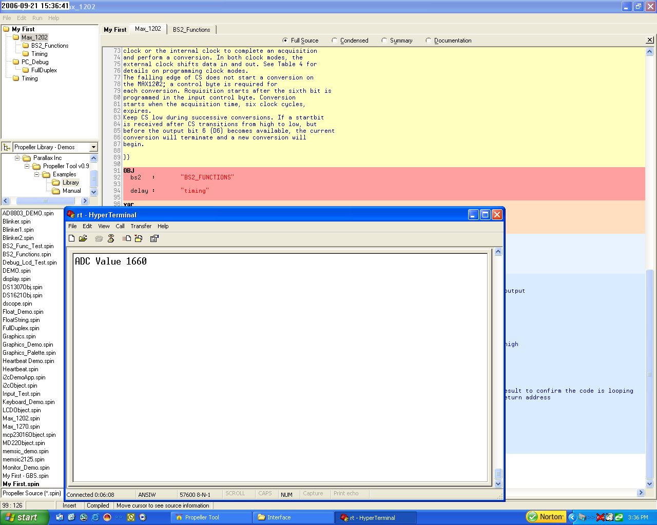
var long Value2Pass long Stack[noparse][[/noparse]24] PUB start (ReturnAddress,control_bit) Value2Pass := control_bit cognew(get_value(ReturnAddress),@Stack) PUB changeControl(control_bit) Value2Pass := control_bit PRI get_value(ReturnAddress)| temp dira[noparse][[/noparse]CsAdc] ~~ '' set max 1202 cs pin as output repeat outa[noparse][[/noparse]CsAdc] := 0 '' set max 1202 cs low bs2.SHIFTOUT(AoutAdc, ClkAdc, Value2Pass, BS2#MSBFIRST,8 ) '' send control bit out outa[noparse][[/noparse]CsAdc] := 1 '' set max 1202 cs high delay.pause10us(1) '' pause for conversion outa[noparse][[/noparse]CsAdc] := 0 '' set max 1202 cs low temp := bs2.SHIFTIN(AinAdc, ClkAdc, BS2#MSBPOST,12) '' receive adc value in outa[noparse][[/noparse]CsAdc] := 1 '' set max 1202 cs high long[noparse][[/noparse]ReturnAddress] := temp '' Send ADC value to the return address delay.pause1ms(2) ' wait 2 msecondthanks for the help...it works great now...I can access the total 8 channels of the Adc. I implemented a stop bit to ensure I was getting the right channel.
This worked out good using the Hyperterminal window....the values showed correctly. Now All I have to do is convert the values to their real world value.....that should be easy now.
I'm learning alot.....
James L
Can you post your new improved program? You show part of it here, but not the "DEMO" side. I'm curious about how you have incorporated Mike's suggestions.
Jamesx
Sure....
Note the pause is mainly for viewing the numbers on the Hyperterminal......I have had no pause in the demo.....and it goes real fast.
The top object file in this Zip is the demo object.
Hope this helps,
James
I have started to decipher the code. All I can think is that this stuff needs to be in the manual somewhere. This Object to Object, Method to Method, and Cog to Cog transfer of data
and timing is really tricky. If the example of this thread were carefully teased apart, like the way things are taught in Chapter 3, it might be very helpful for us mere mortals.
These transfers are tricky, but they're huge.
Jim C
I could notate the code completely if you like.....and reload the file.
I plan to do that for myself......This is but a small part of the project I'm currently working on. I need to remember how all of this works as I go through the different sensors to be incorporated within the project. I have about 4 more complex sensor communications to do as well as some logical software functions to be written as well.
It took me over a week to get what you have. I had Mike, Beau, and Paul break this down to a understandable level for me. It took some time for it to sink in.
I found it is very important to have a physical chip(component) to understand what is going on. I tried a large number of different things before i ask for help. Those things I did just confused me. I had hard coded my attempts into my thinking. I just had to start over from scratch with what the guys sent me.
This was the way I eventually got the system to work. I had some pre-conceived ideas of how the system should work.....which it doesn't.
I will say there are not enough examples for me in the manual. I can't say this is the case for everyone. The manual deals with outputs mainly and not passing variables between the cogs. But I found the answers that I needed.......here on the forum .......for which it was designed.
These guys will help.......it may take a couple of different ways of explaining it.....but they will chisel through any boundries that you have.
If it were all in the manual....it would take a year to read.
Just keep trying,
James
I'm not sure that just a couple of examples in the manual would do it. This kind of conceptual framework for parallel processing takes 2 or 3 lectures with some homework in between to teach to most students. It's often a whole chapter or two in a textbook. It's not that it's complicated, it's just different from the way that most people are taught or learn by themselves and they have to kind of put that completely aside to pick up a new way of looking at things. It'll probably take a while and some iterations to figure out a good way to present this stuff (parallelism and how to deal with it).
I remember reading a book about this stuff long ago by Niklaus Wirth who came up with Pascal among other things. He also developed an operating system that assumed parallelism and had semaphores (locknew/lockset/lockclr) and forking (like cognew/coginit) as primitives. It took me a while to really deep down get it and it was an "aha!" moment finally and it was all so clear and simple and right and made sense. Keep plugging away at it.
Mike
That reminds me of an old Zen koan.
"What is the sound of one cog spinning?"
Jim
(and James, regarding a fully documented file: yes that would be great if you have time)
Here is the documented code.
Hope this helps,
James L
I have posted some code here. This is the way i'm starting and stopping my ADc loop. I don't mind this method, but it uses a pin for a bit flag.
Could one of you....or anyone else suggest a different method of doing the same this with locknew,lockset, etc?
I don't mind this method, but if I get short on pins (which I may) I will need a different method of setting a bit flag readable by multiple cogs. I'm used to doing this with PLC's.....yes I do this in real life. Ladder Logic is quite natural for me now. Actually finding·it challenging programming any other way.
Tell me what you think,
James Long
You can just use a byte variable for this purpose. You don't need to use LOCKxxx. Make sure it's initialized to zero before you start the cog.
VAR byte flag
PUB ChangeControl( ... )
  flag := 1  ' release the ADC cog to get a value
  ...
  repeat while flag == 1 ' wait for the ADC cog to finish
PRI get_value( ... ) ' independent cog to read ADC
  repeat
    repeat until flag == 1 ' wait for a request to read ADC
    ...
    flag := 0 ' signal that we're done
If you want to have these routines in separate objects, add a set_flag and get_flag method to the get_value object
ADC object
VAR byte flag PUB get_flag return flag PUB set_flag(f) flag := f PRI get_value( ... ) ' independent cog to read ADC repeat repeat until flag == 1 ' wait for a request to read ADC ... flag := 0 ' signal that we're doneI too have been thinking about how to control my own ADC (MCP3001) on the fly. I wrote a high speed pasm object that I want to simply say, start, then use the values somewhere else. I've been thinking of using the semaphores (locks) to do this, since there are 8 of em. It occured to me this morning, while driving to work, exactly how to scheme it (I plan on doing this this week, after playing with the counters more). My scheme would look something like this (in pseudocode of course):
A)· First, take out any locks needed
---> [noparse][[/noparse]Have the ADC routine continuously look at the checked out lock to see if it is "free"]
C)· (some code running before the ADC values are needed) [noparse][[/noparse]this isn't necessary, just to show that something else can happen in the meantime]
D)· Free the lock (this tells the ADC to run it's routine)
E)· (still in the non-ADC cog) have code that checks the lock if it is locked
F)· when lock is locked by ADC routine, resume code (aka do something)·with new ADC values
NOTE- If your ADC routine is faster than the spin program, then the spin cog may NEVER see the lock as checked out, or should I say, may never have to wait to see that teh ADC is done, csue the ADC code was so fast it locked the lock before spin realized it, not sure if this matters yet
I was planning on seeing how long this takes, but I think the locks work pretty quick. I have a need for the ADC to run at about 25kHz in my project. If I can't get this scheme to work (at that speed), then I'll have to try something else, but I am quite confident that my Oscillocsope will tell me I have succeeded.
I keep thinking about other ways to do this kinda stuff. For instance, using a pin and the Waitpne command, or a method similar to what Mike proposes. But, I keep getting back to the point that this is exactly why the Prop has semaphores. Or better said, this is a perfect time/place/reason to use the semaphores, there are 8 of 'em!!!
-Parsko
Although that is a good way to do it.....I would rather use the lock command. It takes no space as I see....and I need to learn it anyway
Parsko,
If you get the time....send an example....I will have to use the lock command to save space and a pin.
On to the next thing.....getting my output to make sense(max1202). I have yet to master this one. I'm getting closer.
James
Let me try to explain this a little more:
The main program sets the bit via LOCKSET. Now the ADC cog is attempting to see it's value, this is only possible via LOCKSET or LOCKCLR. If LOCKSET is used, the bit will be set in the process of looking at its value and the next look at it will show it is falsely set and start running. If LOCKCLR was used, it would wait until the main code would set the bit, but in the process would clear the bit afterwards, before the main program clears it. This is good for monstable vibrator applications (run once then stop), but not for general indication.
▔▔▔▔▔▔▔▔▔▔▔▔▔▔▔▔▔▔▔▔▔▔▔▔
Paul Baker
Propeller Applications Engineer
Parallax, Inc.
Post Edited (Paul Baker (Parallax)) : 9/27/2006 4:55:12 PM GMT