

Digital Potentiometer
 cclaud2
Posts: 21
cclaud2
Posts: 21
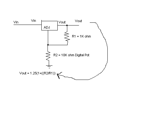
Hi, I am building a circuit to control an·actuator with my BS2.· I am using a voltage regulator(LM317) to regulate·a· 2-10V control signal to the actuator, which is a Belimo LM24-SR.· The circuit works fine if I use a multiturn 1/2W 10K Ohm potentiometer, but when I try and use the 10K ohm AD5220 I cannot get the voltage range that I get with the 1/2W 10K ohm multiturn potentiometer.· I have tried to find a digital pot that is rated for 1/2W with no success.· Does anyone know of a part suitable for this application.· I would really appreciate some input.· Thanks.
I have attached a schematic of the circuit.
Vin = 9V
Vout = Desired 2-10V
R1 = 1K ohm
R2 = 0-10K ohm
I have attached a schematic of the circuit.
Vin = 9V
Vout = Desired 2-10V
R1 = 1K ohm
R2 = 0-10K ohm
Comments
Vout = Desired 2-10V·· Vout cannot be > Vin (see above)
R1 = 1K ohm··········· use a 240 ohm
R2 = 0-10K ohm········ you should not need > 5K
Also, if you look under "POWER SUPPLIES", the power supply (VDD) range is from 2.7V to 5.5V
This is why you are seeing a difference, the output of your regulator is creating a voltage greater than 5.5V across
the digital pot effectively causing it to "clip" or saturate. One solution is to drive the ADJ pin of the regulator with the
output of an OP-Amp (gain set to x2) so that 5Vin should be able to control 10Vout.
In a worst case scenario you would only need a 1/10th Watt resistor if you kept the 1K resistor.
▔▔▔▔▔▔▔▔▔▔▔▔▔▔▔▔▔▔▔▔▔▔▔▔
Beau Schwabe
IC Layout Engineer
Parallax, Inc.
Post Edited (Beau Schwabe (Parallax)) : 2/15/2006 1:28:43 AM GMT
I am using·the 10K ohm AD5220 because it is the only digital pot that I have (it came with What's a Microcontroller).
Everything works fine when I use the 1/2W multiturn 10K ohm pot.· I can get a voltage range from about 1.25V to around 10.5V.· However, when I use the 10K ohm·AD5220 I can only get a range from about 6.0V to 9.0V.· Can you suggest a different pot to use with a higher operating range?· I have looked, but I have had no luck.· Do you have any suggestions?· Thanks.
Please see spreadsheet attached.
▔▔▔▔▔▔▔▔▔▔▔▔▔▔▔▔▔▔▔▔▔▔▔▔
Beau Schwabe
IC Layout Engineer
Parallax, Inc.
I could not find a similar value in the AD5220 spec sheet, but I suspect similarities.
That is nowhere near the wattage. I am talking about .001 amps x 5volts = .005 watts maximum.
They are neat little devices, but they are real power wimps.
▔▔▔▔▔▔▔▔▔▔▔▔▔▔▔▔▔▔▔▔▔▔▔▔
"When all think alike, no one is thinking very much.' - Walter Lippmann (1889-1974)
······································································ Warm regards,····· G. Herzog [noparse][[/noparse]·黃鶴 ]·in Taiwan
·· I had the same concern when I read this thread...Going from a 1/2W POT to a Digital Pot made me wonder...
▔▔▔▔▔▔▔▔▔▔▔▔▔▔▔▔▔▔▔▔▔▔▔▔
Chris Savage
Parallax Tech Support
csavage@parallax.com
About the only thing that I can find is an application that Al Williams wrote, but the voltage swing is very small... (2.4V to 3V)
http://www.catalyst-semiconductor.com/dppstampapplications/
Have you thought about using PWM (Pulse Width Modulation) to control your LM24-SR?·
http://www.greenheck.com/pdf/dampers/LM_Series.pdf
My approach on this would be to use the PWM function of the BS2 to set a reference voltage of (0V to 5V) to the input of an OP-Amp.
With an Op-Amp set with a gain of X2 and powered by a 10V supply (0V to 5V becomes 0V to 10V) which should be able to drive the
input of the LM24-SR.· The input impedance of the LM24-SR is only .1mA (100K) at 10V so a standard LM741 should work just fine.
▔▔▔▔▔▔▔▔▔▔▔▔▔▔▔▔▔▔▔▔▔▔▔▔
Beau Schwabe
IC Layout Engineer
Parallax, Inc.
One other side note these actuators are not meant for continuous repositions. We found this out the hard way on a site, where the controls were moving the actuators every 5 or 10 seconds that they wear out within a year or two. The factory told us that it is best to keep repositions to 30secs or so. They carry a five year warranty, but it won't cover abuse like this.
Previously I had mentioned a gain of X2... Actually you need at least X4 because you would be using the Op-Amp in a single supply
mode.· Below is a schematic that might get you started.·
Note: the 4.7K could be substituted for a 5K trim pot to adjust your gain.· Once this is set, you probably want to leave it alone.
Orion,
"The problem you may run into with PWM is the stamp will be stuck doing this and unable to process any other commands."
By placing a voltage follower at the beginning you can reduce this problem.· You still need to make regular PWM updates.· Increase
the 1uF cap to 10uF·for longer periods between necessary updates.
cclaud2,
Or you could just use the digital POT
▔▔▔▔▔▔▔▔▔▔▔▔▔▔▔▔▔▔▔▔▔▔▔▔
Beau Schwabe
IC Layout Engineer
Parallax, Inc.
Post Edited (Beau Schwabe (Parallax)) : 2/15/2006 5:50:38 PM GMT
Beau, thank you especially for the circuit you drew and your other feedback.· That is very helpful.· I am going to give it a shot with the Op Amp and see if I can get it to work.· Thanks again.