

Radio Control Encoder from an SX
 Wreno
Posts: 26
Wreno
Posts: 26
What I would like to do is:
Take input from 8 pots and perhaps a couple of switches, do a little logic and calculation, and output the information in a 20ms pulse frame compatible with standard hobby r/c. This is the format generated by the encoder in the radios. The purpose is a customized buddy-box.
Basically, this is a replacement for the common NE5044 chip used in hobby radios.
Most of the pot inputs are just read and the level passed through (or reversed, or limited, or mixed, then passed through) in the encoded format. So far, a hobby RC radio can already do this. What I want to do with a few of the channels, a hobby radio generally cannot do. Plus, with this encoder, you can turn a basic, inexpensive, 4 channel hobby radio into a powerhouse 8 channel computer controlled unit.
Explanation follows at various levels of detail, and I am enclosing drawings for clarification:
The basic constraints: Does the SX have the clock speed speed or oomph to handle all this (8 - 10 pot reads, 3-4 if-then-elses, a little calculation, and output 9 precise pulses on one pin based on that information every 20 ms)? I am thinking it will need to do the reads/calculations/timekeeping/etc. in the dead space of the frame, which could be as little as 4 ms.
30,000 ft. view: I am involved in R/C model Warship Combat (see www.ntxbg.org). The object is to get more shots on target. Using the following, grossly simplified, assumptions:
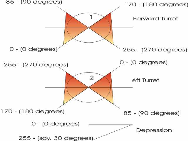
The ship has 2 turrets, one in the bow, one in the stern (1 and 2, or A and D, respectively)
Each turret has about a 270 degree field of fire.
For clarification A (or 1) being 135 degrees either side of the centerline of the ship going forward, 0 being the CCW end of motion or stop, with 45 degrees from the 0 position being 90 degrees from the centerline of the ship on the left, or port side, 135 degrees being dead ahead, 225 degrees of rotation being 90 degrees to the right (starboard) of the centerline, and 270 degrees of rotatin being the tull stop on the right.
D (or 2) being the same as A, but rotated 180 degrees (center, or 135 degrees of rotation, is dead astern).
Both turrets are controlled by 270 degree pots on a 1:1 basis. So far, so good, my RC radio can do this.
Note, however, that the fields of fire have an overlap of about 90 degrees on each side - 0-90 on A overlaps with 180-270 degrees on D, and 180-270 degrees on A overlaps with 0-90 degrees on D.
The guns use a third pot to dial in depression for close-in targets.
Several other controls are used in the ship, but those are relatively straightforward, pretty much 1:1 just like a simple RC hobby radio (EPA is the most complicated adjustment necessary), so let's focus on the 3 channels that need fudging for now.
What I would like to have happen:
When you flip a switch to enable master/slave mode, D goes to parallel with A if it can, and ignores its own control. If it cannot, it goes to wherever its control is set.
Better yet, adding more depression closes the angle of D relative to A so that the barrels tend to converge on a single spot.
Considering an 8 bit representation of 0-255 being 0 to 270 degrees, what I have come up with so far:
syntax: pot1 is the value at pot1, tur1 is the value to be output to control the turret. 1=A, 2=D, 3=depression (range fudge factor)
tur1 = pot1
IF pot1 < 86 THEN tur2 = pot1 + 170
ELSEIF pot1 > 170 THEN tur2 = pot1 - 170
ELSE tur2 = pot2
ENDIF
This should give you a parallel fire with A as the master, D as the slave, when A is in the sweet spot.
Of course the "convergence" tweak, in the same format, is:
dep=pot3
tur1 = pot1
IF pot1 < 86 THEN tur2 = pot1 + 170 + (pot3 / 10)
ELSEIF pot1 > 170 THEN tur2 = pot1 - 170 - (pot3 / 10)
ELSE tur2 = pot2
ENDIF
The results will need to be limited to 0-255, of course.
What I am thinking is to build this into a controller box of choice, and then plug it into the radio as the pulse stream commonly encoded in RC prior to the RF stage, which is accessible through the buddy-box port.
Does this sound easy, difficult, impossible? Especially for a newbie? Has something similar already been done that you can point me to?
If it helps to do so, picture that I am wanting to build as a custom "BuddyBox" trainer system. They do the same thing (without the smarts), just take the baseband ppm signal from the encoder of the trainee's radio and feed it through the buddy box port of the trainer's radio to the RF stage as long as the trainer holds the switch closed. Release the switch, and he seizes control back to his encoder stage.
There is a pretty good explanation of the structure of the output signal required at www.geocities.com/BourbonStreet/3220/servotx.html
Hardware recommendations and programming suggestions are certainly appreciated.
Thanks,
Wreno
Take input from 8 pots and perhaps a couple of switches, do a little logic and calculation, and output the information in a 20ms pulse frame compatible with standard hobby r/c. This is the format generated by the encoder in the radios. The purpose is a customized buddy-box.
Basically, this is a replacement for the common NE5044 chip used in hobby radios.
Most of the pot inputs are just read and the level passed through (or reversed, or limited, or mixed, then passed through) in the encoded format. So far, a hobby RC radio can already do this. What I want to do with a few of the channels, a hobby radio generally cannot do. Plus, with this encoder, you can turn a basic, inexpensive, 4 channel hobby radio into a powerhouse 8 channel computer controlled unit.
Explanation follows at various levels of detail, and I am enclosing drawings for clarification:
The basic constraints: Does the SX have the clock speed speed or oomph to handle all this (8 - 10 pot reads, 3-4 if-then-elses, a little calculation, and output 9 precise pulses on one pin based on that information every 20 ms)? I am thinking it will need to do the reads/calculations/timekeeping/etc. in the dead space of the frame, which could be as little as 4 ms.
30,000 ft. view: I am involved in R/C model Warship Combat (see www.ntxbg.org). The object is to get more shots on target. Using the following, grossly simplified, assumptions:
The ship has 2 turrets, one in the bow, one in the stern (1 and 2, or A and D, respectively)
Each turret has about a 270 degree field of fire.
For clarification A (or 1) being 135 degrees either side of the centerline of the ship going forward, 0 being the CCW end of motion or stop, with 45 degrees from the 0 position being 90 degrees from the centerline of the ship on the left, or port side, 135 degrees being dead ahead, 225 degrees of rotation being 90 degrees to the right (starboard) of the centerline, and 270 degrees of rotatin being the tull stop on the right.
D (or 2) being the same as A, but rotated 180 degrees (center, or 135 degrees of rotation, is dead astern).
Both turrets are controlled by 270 degree pots on a 1:1 basis. So far, so good, my RC radio can do this.
Note, however, that the fields of fire have an overlap of about 90 degrees on each side - 0-90 on A overlaps with 180-270 degrees on D, and 180-270 degrees on A overlaps with 0-90 degrees on D.
The guns use a third pot to dial in depression for close-in targets.
Several other controls are used in the ship, but those are relatively straightforward, pretty much 1:1 just like a simple RC hobby radio (EPA is the most complicated adjustment necessary), so let's focus on the 3 channels that need fudging for now.
What I would like to have happen:
When you flip a switch to enable master/slave mode, D goes to parallel with A if it can, and ignores its own control. If it cannot, it goes to wherever its control is set.
Better yet, adding more depression closes the angle of D relative to A so that the barrels tend to converge on a single spot.
Considering an 8 bit representation of 0-255 being 0 to 270 degrees, what I have come up with so far:
syntax: pot1 is the value at pot1, tur1 is the value to be output to control the turret. 1=A, 2=D, 3=depression (range fudge factor)
tur1 = pot1
IF pot1 < 86 THEN tur2 = pot1 + 170
ELSEIF pot1 > 170 THEN tur2 = pot1 - 170
ELSE tur2 = pot2
ENDIF
This should give you a parallel fire with A as the master, D as the slave, when A is in the sweet spot.
Of course the "convergence" tweak, in the same format, is:
dep=pot3
tur1 = pot1
IF pot1 < 86 THEN tur2 = pot1 + 170 + (pot3 / 10)
ELSEIF pot1 > 170 THEN tur2 = pot1 - 170 - (pot3 / 10)
ELSE tur2 = pot2
ENDIF
The results will need to be limited to 0-255, of course.
What I am thinking is to build this into a controller box of choice, and then plug it into the radio as the pulse stream commonly encoded in RC prior to the RF stage, which is accessible through the buddy-box port.
Does this sound easy, difficult, impossible? Especially for a newbie? Has something similar already been done that you can point me to?
If it helps to do so, picture that I am wanting to build as a custom "BuddyBox" trainer system. They do the same thing (without the smarts), just take the baseband ppm signal from the encoder of the trainee's radio and feed it through the buddy box port of the trainer's radio to the RF stage as long as the trainer holds the switch closed. Release the switch, and he seizes control back to his encoder stage.
There is a pretty good explanation of the structure of the output signal required at www.geocities.com/BourbonStreet/3220/servotx.html
Hardware recommendations and programming suggestions are certainly appreciated.
Thanks,
Wreno
640 x 480 - 21K

640 x 480 - 22K
Comments
http://www.mh.ttu.ee/risto/rc/electronics/radio/signal.htm
▔▔▔▔▔▔▔▔▔▔▔▔▔▔▔▔▔▔▔▔▔▔▔▔
Jon Williams
Applications Engineer, Parallax
Good pointer, Jon, Thanks.
Wreno
▔▔▔▔▔▔▔▔▔▔▔▔▔▔▔▔▔▔▔▔▔▔▔▔
Meh. Nothing here, move along.
Wreno
Wreno
If there is anything about RCTIME you want to be further explained, ask and I or someone else will do our best to explain it enough so you'll understand it fully.
▔▔▔▔▔▔▔▔▔▔▔▔▔▔▔▔▔▔▔▔▔▔▔▔
·1+1=10
Post Edited (Paul Baker) : 1/30/2006 6:50:33 PM GMT
▔▔▔▔▔▔▔▔▔▔▔▔▔▔▔▔▔▔▔▔▔▔▔▔
Jon Williams
Applications Engineer, Parallax
Conceptually:
ADC reads the post and keeps track of the values of each in some internal register relatively continuously
The SX then:
1) Gets the 8 pot values from the ADC (something like a serial read?) about once every 20ms
2) Does Calculations and logic to generate the output stream
3) outputs the output stream (encoded pulse width modulation frame).
Is this correct?
Wreno
You should also consider putting the logic shipboard between the RX and the servos. No need to hack your transmitter, just plug the SX between the receiver and your servos.
The SX-Creeper code has all the R/C Inputs and Outputs you would need, and then some. Rip out the Serial, Parser, EEPROM, Gait and Stride logic, and put in your Tageting logic giving programmed R/C outputs for various R/C inputs. Voila!
I can even envision other features, like automatic rapid fire!
-AGM-
The other problem is the inability to have additional external controls this way - you are limited to the 8 channels of input. Putting this in at the TX end allows you unlimited inputs, but only 8 outputs (in other words, you can select different mixes or mix conditions locally for implementation remotely).
Although we frequently hack the TX's, the reason for my approach was to set this up through the buddy box connection - no real hacking, just changing the trainer switch from momentary. Then the module can also be used on multiple radios or even as an encoder for different types of RF (like 900 Mhz).
Wreno
Haven't coded anything significant in a long time - last major project was on an AT&T PC-6300, and, trimmmed for max efficiency, doing integer math (though I had the math co-processor), and properly compiled, this less than 100 line program to determine a 2 dimensional pareto-optimal curve result took 4 days of continuous CPU time to run (only bothered to update the screen with a ticker every 100,000 iterations or so)! I've sometimes considered trying to dig it out of the archives and run it on a more modern machine... Oh, and yes, my result in the exercise that the curve was generated from was on the curve at the maximum positive extent possible for my group. Cool. I was proud of that. Fun times.
Wreno
One question you asked was if the SX has the horsepower. The answer is a definite yes. You said that a lot of work has to be done in the dead space which could be as short as 4 ms. 4 ms? That's a big chunk of time for a high speed SX chip. One really cool aspect of the SX is that with a 50 MHz clock and most instructions running in a single clock cycle, you can execute up to 200,000 (yes, that's two hundred thousand) instructions in 4 ms. I think you'll get the job accomplished with time to spare.
With regards to the question of whether this is something an SX beginner can do, the answer depends on how you approach the problem. You apparently already know how to program, so now you need to approach a new processor with a fairly big task. Personally, I would do the following:
1 - Write the classic "blink an LED" program.
2 - Write a small program to read a switch and turn on an LED.
3 - Re-write it to use interrupts. You did write version one as a polled version, right?
4 - Write a program to read whatever ADC you're going to use.
5 - Write a program to generate a single RC style servo pulse stream.
6 - Re-write the servo program to generate 8 different multiplexed streams.
7 - Integrate the ADC reading code with the code to write 8 multiplexed servo streams.
8 - Clean up the code and add the remaining goodies.
Here's what I wouldn't do:
1 - Get the SX kit in the mail.
2 - Try and write a program to read multiple ADCs and output 8 multiplexed servo streams using interrupts.
3 - Get frustrated and decide the SX sucks.
4 - Never complete the project.
I never cease to be amazed by the number of folks who decide that the first project they want to do is some monster that would tax an experienced SX programmer - all without ever trying to do something smaller first!. Of course, lots of people will look at my list of 8 steps and think, "Yeah, but why re-write so much stuff? For example, why not combine step 1 and 3 and just make the first blinking LED code interrupt driven?" The answer to that can be seen in my list of what I wouldn't do.
One last thing to mention is that can try to write the project in SXBasic if you're not thrilled with the idea of writing a pile of assembly language code. The point I'm trying to make is to approach this project not a single project but as a series of projects with a learning curve that shouldn't be so steep as to make you give up.
Thanks, PeterM
The signal is, how to say this, kind of, kind of not the same as the PWM signal the servo uses.
It is an encoded signal with all 8 inputs in a 20ms frame.
However, keep in mind that, not only do I want to do mixes that the radio cannot do, but I may want different physical controls (in placement, number, and type) than on the actual radio box (which was designed for flying airplanes or driving cars, depending on style, and may not be optimal for battling warships). This includes 8 analog (pot) inputs and multiple digital inputs (switches), and may eventually include some outputs (firing interval indicators, ammo status based on shots fired, etc.)
Wreno
How sophisticated of a fire-control system can you use? It seems like this would be a good place to use a Ping sensor for ranging information, as well as a wireless camera for visual feedback.
You are getting in to 2 way communications requiring lots of bandwidth. While this is possible, it is not possible with standard R/C equipment which is one-way for the most part.
Remember, we have an aerial view of all the action. While gun cameras are "cool," most clubs allow them only if you are in a booth without the full battlefield view. Keep in mind that you are maneuvering your ship at the same time you are battling, and you will soon come to realize that you want to "keep your head out of the cockpit" or you will quickly be in serious trouble. Situation awareness is vital. Anything that distracts from that awareness can be dangerous.
That is the whole reason for my exercise - to automate the stern turret(s) when possible to remove the task of aiming them from the operator, reducing operator workload. What I am trying to do is not complex, it is just something most radios, set up as they are for flying planes, have no reason to be able to do, and, thus, most cannot.
Wreno
I am working a project that runs 8 switches from a buddy box. I am using a single channel as a serial line with 1mS as low, 2mS hi, and a SX based decoder VP at the RX. At 20 mS per bit, it is no speed demon, but for 8 switches and my application it's fine.
The buddy box signal TX signal is no problem for the SX, it idles most of the time - lots of time to read 4-5 pots, I would think.
The decoder at the RX is kind of tricky, but works. Mine is running a LCD (UART VP), tachometer, and clock in addition to the 8 switch signals. Cylinder head temp sensor is next, if I can figure out a 1-wire VP ...
I am not trying to do much math at either end, so I can't comment on calculating your field of fire, etc. But I did have a thought that might be workable - How about an RC heli gyro (heading lock mode) on the turrets to keep them on target while you maneuver around? At least they would be pointed at the last place you were shooting at. In combination with some more advanced programing at the TX, could be fun.
I've got some buddy box code you could play with on the SXSim (wonderful tools, by the way) before you sink any money into HW. Let me know if Ya want to play with it, It will need a little clean up for generic use.
Larry
Post Edited (les_blue) : 2/2/2006 10:55:15 AM GMT
I would love to look at the code you are taling about. Sounds like it is right in the same neighborhood as what I am trying to do.
As for the gyro - very interesting thought, but I am not sure how well it would work in our application. First, while it would keep the gun pointed in relatively the same direction during maneuvering, which would be nice if you were the gun operator independently, keep in mind that the operator here is also the captain and is juggling ship and guns at the same time, and has to think of them as a unit. You want to know where your guns are pointed relative to the ship. Often (usually) you are using the maneuvering to bring your guns to bear in the final stages of the attack run. If the guns are being tweaked by a gyro, you do not know exactly where they may be aiming relative to the ship. A better use for gyros is in depression, to compensate for roll, but they are limited here as well due to the requirements for no positive elevation. They have been tried repeatedly in the elevation role by various captains with no real joy as to effectiveness. Easier to use the MK I eyeball.
Yes, no positive elevation = no plunging fire, only direct fire. So we are using 21st century technology to battle early 20th century warships in 19th century style (shooting round steel balls at each-other's wooden ships).
Thanks,
Wreno
At some point, You have to make a choice or get a gunner's mate!
So in my scenario, Skipper would :
Aim at boat
Maneuver around target
In your case, Skipper would :
Maneuver around target
Aim at boat
I'll bet this could be selected in software.
The cool thing about software is that is only limited by project time, cost and physics.
I'll clean the encoder basics up and send it.
Larry
Post Edited (les_blue) : 2/2/2006 11:39:31 PM GMT
I appreciate the help.
Keep in mind that on the Graf Spee that my son used to battle, it was set up with a rotating bow turret and a fixed (non-rotating) turret. You aimed the stern turret solely by aiming the stern of the ship. An attack run would go something like this:
It looks like the target will be open on my starboard side,
set forward guns to the point of attack I have chosen (directly abeam starbard, forward of abeam, aft of abeam depending on the angles and apparent timing),
Start attack run, when the guns are lined up with where I want on the target, fire
Turn Hard to port
As the stern gun lines up, fire.
Remember, target and shooting platform are both moving at the same time.
Wreno
Sorry for the delay, I'm trying to get several projects wrapped up at the same time.
This is the hard coded version for 8 switches on a 2 channel radio, should give you some idea of the program flow. It will be implemented as a VP at some point. It is just the 'Buddy box' test signal generator at this point. Basic setup is:
In:
8 inputs on port B, pull to ground for 'on' state
Out:
RC.0 is the composite (Buddy Box) signal
RC.1 is a 'clock bit', constant '1' (2mS servo out)- I thought i needed this, but it is unused
RC 2 is the serial data bit (1/2 mS servo out) contains the 8 encoded switches
Notes:
Ignore the LCD stuff, it is my standard 'debug out' for this board and is jumped over in this code.
RC.1 (RC channel 1) is where I would wedge in an attempt at a servo 'RCTIME' input.
In this build, if no switch is pulled low (RB.0-7), a walking bit is sent on channel 2 for my testing purposes.
You may need to invert the output signal on RC.0, depending on your hardware.
Sorry for the crude nature of the code, I've got my hands full getting the hydroplane that this code feeds ready for it's season opener in a few short months.
Larry
Thanks for the code. I have glanced at it, and will ponder it and how to incorporate it. It looks like the output routine is relatively straightforward, if I am understanding it right. Also, I appreciate the explantions as to the other bits, so that they are not "a mistery." [noparse]:)[/noparse]
Good luck with that hydroplane! Most clubs have an off season for building and development (hard to cruse when the pond is iced over). In Texas, the weather is generally mild in these parts, so our club has battles every month. We get a lot of battling and gunnery in, but it is sometimes hard to keep up. Especially when we are trying to build "that next ship" at the same time. And design new gun/torp systems. And develop new control systems. And, of course, have something of a life. [noparse]:)[/noparse]
Again, thanks.
Wreno
Hope it helps. It's part of a safety program for the 'big' boats, with on course / in dash warning lights. RC stuff works well for prototyping in this case.
Attached is a pic of the hydro build, for your amusement - not RC, but full scale. The 8 switches are the 'flags' red,yellow green...
for the driver.
Larry
1:1 is indeed LARGE scale. Cool.
Of course, with 1:1 and no RC, if something goes drasitcally wrong, it is yourself on the line instead of just your work and $s. Safety is definitely to be desired (of course, with 1/4" steel balls travelling about 200 f/s, and multiple pressure vessels in use on each ship, we take safety seriously as well).
Good luck in the next season!
Wreno
Update for the 8 channel. Still an inline 'hack' but I know this works. Of course, all the pins/ports changed when I stuffed it in the real 'buddy box'. Let me know when You get to the point of actually hooking up to the port, I'll tell You how NOT to smoke the inductors in the TX. Futaba and Hitek don't allways play well together.
I really just wanted to show off some pics from the Parallax scope that the UPS guy left on the porch.
Larry
Thanks. I particularly like the screenshots. So that is the new SB Parallax sillyscope? Have you had it long enough to form an opinion as to it's suitability for this type of analysis (I was kind of looking at it myself). I have some PICs and programmer on the way to tinker with, and am getting anxious to tackle the learning curve.
I will look at and ponder your code. Thanks for the help.
Wreno
Just got the scope today. I found my bug in the decoder with SXSim before it arrived, so I have not done much serious work with it yet. From a quick glance, I like it, easy up and running, does the job I expected for the price.
What are You doing playing with PICs? Just say 'SX28,turbo,stackx,optionx' , and don't look back!
Larry
I kind of enjoy hitting the "minimalist" button sometimes instead of the Tim "The Toolman" More Power button. And, a friend was dumping his unused PIC stash in favor of AVR. Gotta start somewhere. And, one of the guys in our Warship Combat club is a PIC guy, who offered to help me get up to speed. I figure, if I can do it at all on a PIC, I can do it better on an SX, and, in theory, any PIC stuff should port over pretty nicely. After all, isn't PIC pretty much a slower subset of the SX? Or, to put it another way, the SX is a PIC on steroids and caffein?
Wreno
Nothing wrong with the PICs, I was just putting a shot across the bow, since this is the SX section of the forum.
It's hard to debate the success of Microchip's stuff. I'll bet my dishwasher has some of thier silicon embedded in it.
Larry
Got ya. Figured the same. You will soon figure out that I also tend to be a cross-pollinator-type cuss (although a Big Gunner, I also hang out and participate on the Small/Fast Gun lists). I happen to be a believer that, just because I have a hammer, not all problems are nails. Even though you can hammer a screw if you want instead of using a screwdriver (been there, done that, too). Regardlesss, while the SX is the end goal, I don't want to ignore other tools that may prove useful along the way.
More importantly, as I thought about it, you mentioned some porblems with pluggin in through the buddy box port. The radio I plan to use is Futabe 6-pin compatible. I was planning on checking voltage levels, etc. prior to hooking up, but didn't realize there was anything to be particularly nervous over. I would appreciate any cautions/hints you have.
Thanks,
Wreno