

SX28 LED Moving Display Sign (ported from a BS2px)
 T&E Engineer
Posts: 1,396
T&E Engineer
Posts: 1,396
I have ported over·a·SX28 version of a 20 column LED moving display sign originally written for a BS2 series (e.g. Bs2px).
See this link for more info on the BS2 version.
http://forums.parallax.com/showthread.php?p=561144
It runs a bit faster on the SX28 than on the original BS2px so some variables (e.g. Delay) were updated to compensate.
Now the project went down in cost by $75 by moving from a BS2px ($80) to a SX28($5).
However, it is much easier to develop on·a BS2 series and later port it to an SX28 to bring cost down.
Comments.
Thanks,
Timothy Gilmore
Post Edited (tdg8934) : 12/9/2005 3:17:11 AM GMT

Comments
Just wondering how long it took to convert a working project on the stamp to the SX28 ?
Nice project by the way...
Bean.
▔▔▔▔▔▔▔▔▔▔▔▔▔▔▔▔▔▔▔▔▔▔▔▔
"SX-Video·Module" Now available from Parallax for only $28.95
http://www.parallax.com/detail.asp?product_id=30012
"SX-Video OSD module" Now available from Parallax for only·$49.95
http://www.parallax.com/detail.asp?product_id=30015
Product web site: www.sxvm.com
Those that would give up freedom for security will have neither.
·
Im pretty impressed with this project!
Tim
i need a littel more time to look at the code, but what can you make this circuit DO.· What have you made it do?
▔▔▔▔▔▔▔▔▔▔▔▔▔▔▔▔▔▔▔▔▔▔▔▔
It's Only A Stupid Question If You Have Not Googled It First!!
You can control how fast the messages move across the screen. It is done by DATA statements for each column of data being pushed across the screen. It actually does this very fast over and over and creates a persistance of vision optical illusion.
You can create custom characters or symbols. I will attach an excel file that shows how to create the DATA statements for numbers and letters and symbols.
I hope this answered your questions.
Thanks,
Timothy Gilmore
Maybe you can help me. i am making a little flying wing with leds on the bottom side. if i put 10 columns on each wing and tied them together to resemble your diagram, could i make it do things like each wing //// \\\\ starting at center and moving to the wing tips. How tricky would that coding be and can i do it with the current hardware setup? Do you by any chance fly? If you could help me figure out the code, i would assemble the airframe with LEDs and circuit for your troubles. I am looking to make the sx28 'monitor' the PWM from the RC reciever, and depending on its width, do a different preset function ie.. center-to-tips or leading edge-to- Trailing edge or random flashing. What do you think?
the plane is about 20" wingspan. It is a foam core that i usual glass and paint, but for this app i ws thinking of using SMD LEDs tied together with thin wire, layed between the glass and the foam core. The glass cure clear and should be quite impressive. Just have to work out the code thing. Thanks for your time Tim. BTW, the code porting looks great.
▔▔▔▔▔▔▔▔▔▔▔▔▔▔▔▔▔▔▔▔▔▔▔▔
It's Only A Stupid Question If You Have Not Googled It First!!
Your project would not be hard at all to do. Although the scrolling hardware (4017's) would have to be doubled but they are very cheap. I will help you in anyway I can by first redesigning my drawings for your application.
We can use SX28 RC outputs for the left wing and RB outputs for the right wing this way·you can have 10 or more columns on each wing.
The data statement will be more than a standard·5 column·width which doesn't mater·as the hardware is scrolling·individual columns anyway.
DATA 1,2,4,8,16,32,64
and also other code modification such as:
Reset_4017RB·· VAR···· RA.0
Reset_4017RC···VAR···· RA.1
DisplayRB······ ··VAR···· RB
DisplayRC········ VAR···· RC
Clk_4017RB·· ····VAR···· RB.7
Clk_4017RC······ VAR···· RC.7
:
DisplayRB = TempResult···· 'light up the correct Rightside LEDs
DisplayRC = TempResult···· 'light up the correct Leftside LEDs
:
DisplayRB = 127··········· 'turn off all Rightside LEDs
DisplayRC = 127··········· 'turn off all Leftside LEDs
...and·the scrolling·hardware will be wired·in the opposite direction for each wing.
I do not fly but travel alot with my job as a Lead Test Engineer which I do enjoy.
More later...I hope this helped.
Thanks,
Timothy Gilmore
Post Edited (tdg8934) : 12/8/2005 1:04:50 PM GMT
Your first project looks good. Just the other day you were a neophyte, today, you have made some big gains, I'm impressed. I have piddling around for some time now, and I do not feel that I am making any big progress.
I have a Test and Field Engineering background. I do have an Electrical Engineering degree but hardly utilized it for hardware / software design type work which is my passion. This leads me to the point of minimal experience in the real world so I am taking it upon myself to teach myself and get involved any way possible. I have over 25 years in electronics but I really enjoy microcontrollers and computer controlled devices. Especially anything visual or video based. This is why you have seen projects such as my Talking Video clock (www.sxvm.com) and now a LED Moving Display sign. I make sure first that I am not re-inventing the wheel but doing my homework and do some websearching to see what other people have done to understand the concept of the design as best as you can. However for this project there was nothing for the BS2 (other than the ROBOLYMPIC design for the SX28 which used an Interrupt which I need to understand that a bit better). However, that good design was limited to basicly 3 characters. My design doesn't care how many characters·are·sent out.
A few·years ago I bought a Chrismas·Karioki type sing along with a huge LED message sign on closeout from $200 to $30. I bought 2 and took·one apart and·learned how the scrolling was·done. Ever since then, I have been very interested in·designing my own sign.
I do admit that I do spend at least·3 hours a day with my projects and much more time on the weekend. This is to say when my wife doesn't pull me away to eat dinner or get out of the house. I am very happy that I have found Parallax and their great products. I have spend hundreds of dollars in my·work but I have the resources / components available when I need them. I have come along way in a short time but I put the time in to learn and grow to become hopefully a better designer and·hobbiest·in the future.
All I can say is ask questions if you are not sure and take educated risks. Parallax staff and others on this forum has made a world of difference to me. I have certainly made errors as Jon and Bean can attest to that but push yourself to new levels.
The hardest issue I have is not how to design something but WHAT to design next that I have a good enough grasp on to move forward on it.
Take care,
Timothy Gilmore
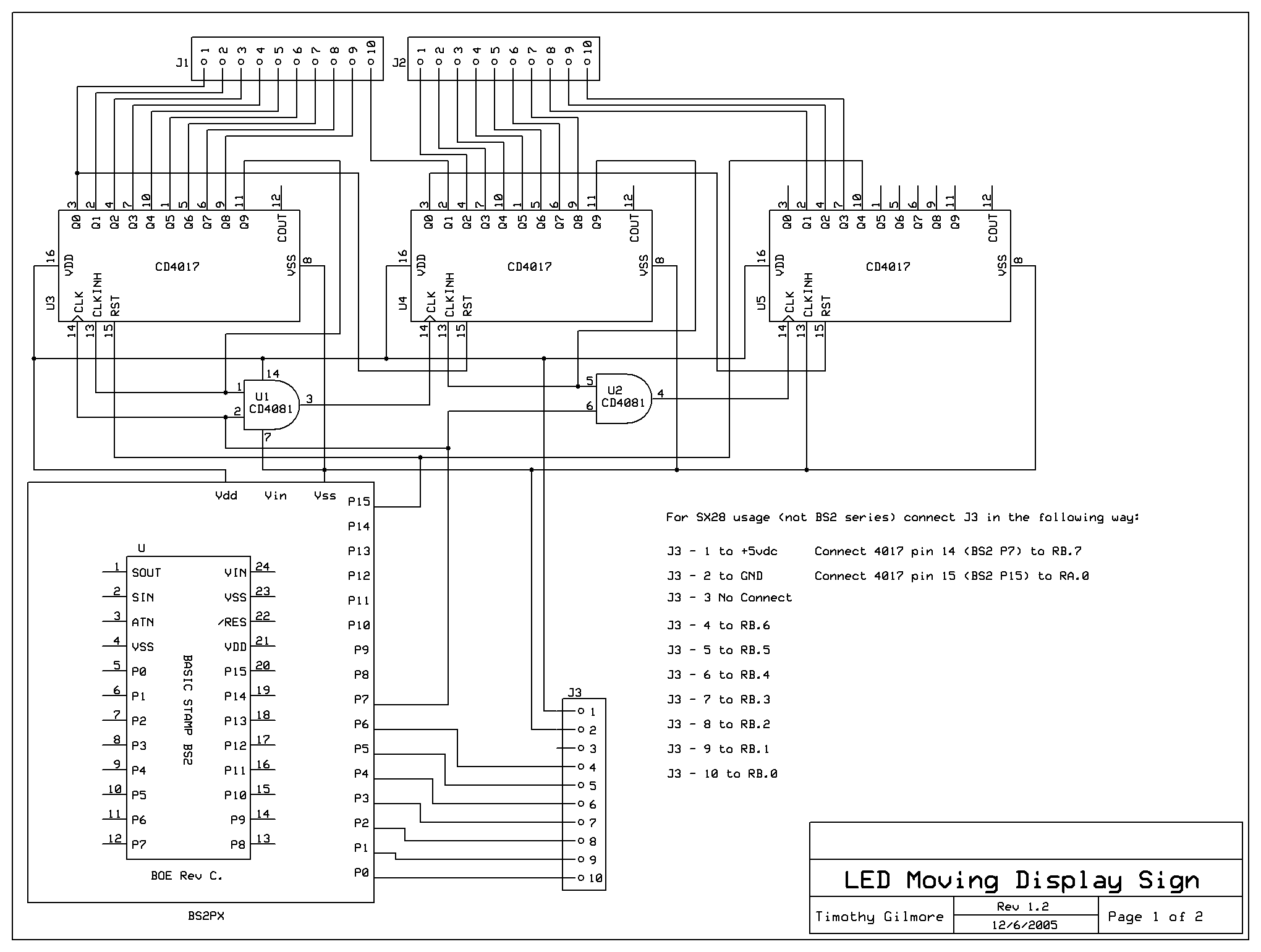
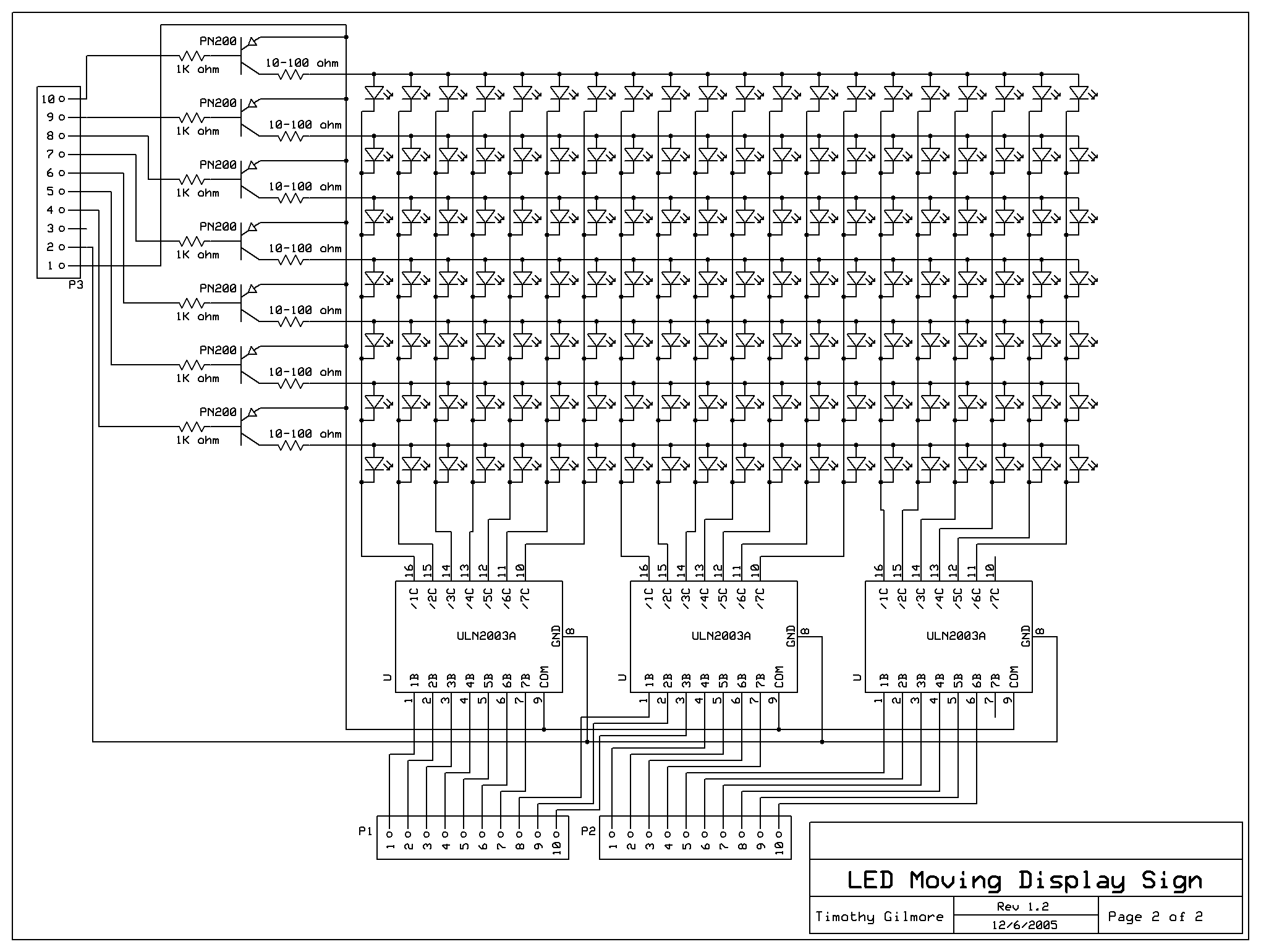
I have tested the hardware and software (attached) and it all works. This is what you need to do from the drawing 1:
You will need to add another Drawing 2 circuit AND add·3 4017 and 1 4081 circuit as in the drawing for the left wing but follow the connections below. BASICALLY DOUBLE both drawings but you will only need (1) ONE SX28 as the left wing will connect to RC outputs and RA.1.
Add·J4 (like J1)·and J5 (like J2) and·reverse the wires from J1 and J2 for the "left" wing.
J4-1 4017(3) pin 7
J4-2 4017(3) pin 4
J4-3 4017(3) pin 2
J4-4 4017(2) pin 9
J4-5 4017(2) pin 6
J4-6 4017(2) pin 5
J4-7 4017(2) pin 1
J4-8 4017(2) pin 10
J4-9 4017(2) pin 7
J4-10 4017(2) pin 4
J5-1 4017(1) pin 2
J5-2 4017(1) pin 9
J5-3 4017(1) pin 6
J5-4 4017(1) pin 5
J5-5 4017(1) pin 1
J5-6 4017(1) pin 10
J5-7 4017(1) pin 7
J5-8 4017(1) pin 4
J5-9 4017(1) pin 2
J5-10 4017(1) pin 3
In addition to the SX28 connections on drawing 1, also add the following connections for the "left" wing.
Connect the left wing connections to RC.0 to RC.6 (as similar to the right wing connections in Drawing 1) to RB.0 to RB.6
Connect the Reset for the New 4017 left wing circuits to RA.1.
Connect the Clock for the New 4017 left wing circuits to RC.7.
See the new attached code.
Thanks,
Timothy Gilmore
Post Edited (tdg8934) : 12/9/2005 3:24:45 AM GMT
Really going for the wow factor on this one.
▔▔▔▔▔▔▔▔▔▔▔▔▔▔▔▔▔▔▔▔▔▔▔▔
It's Only A Stupid Question If You Have Not Googled It First!!
have you ever played with the maxim-ic max6952? Im thinking that is is very similar to what you have made but lots less components. Any thoughts?
http://www.maxim-ic.com/quick_view2.cfm/qv_pk/3379
▔▔▔▔▔▔▔▔▔▔▔▔▔▔▔▔▔▔▔▔▔▔▔▔
It's Only A Stupid Question If You Have Not Googled It First!!
You can always·NOT cascade the CD4017 and use only 10 columns of LEDs (* 7 rows). This would mean you would only reduce 2 wing circuits by 5-6 IC's (4 CD4017 and 1-2 CD4081 IC's)
You will need the following components for 2 5x20 displays:
280 LEDs, 14 PN200 darlington high current PNP transistors, 14 10 ohm resistors, 14 1K ohm resistors, 6 ULN2003A IC's, 3 spools of different colored hook up wire (22-24 guage)-Radio Shack, 6 CD4017 IC's, 1-2 CD4081 IC's, [noparse][[/noparse]1 SX28 IC, 1 10K ohm resistor, 1 4 MHz resonator, 1 push button switch, etc..·{see page 6 of the "Programing the SX Microcontroller"}], ~25 watt soldering iron, thin solder spool, desoldering braid, 2 solderless breadboards (or 2 custom perferated boards - 5x6" min - 6" is min size to barely fit 20 columns of LEDs).
Also to power all the LEDs you will need a good power supply with more current. It may not be possibly with batteries to make them last long. Some C or D cells with a regulator circuit to 5 vdc. Isn't this too much weight for the plane?
I don't know about the·Maxim 6952·but the Maxim·7219·is expensive and it only handles 8 LED columns each IC I believe - never used it but read the specs. So at $20 each IC * 6 (3 * 2 circuits) it was not worth doing.
The CD4017 I bought 5 for $3. There is always other·design strategies. However, most engineers use first what they know and if not,·what ever has the·easiest learning curve to do the job.
Thanks,
Timothy Gilmore
I hope to incorporate the new more (unfortunately more expensive) approach in my design.
However, I don't see any posts about this IC other than·this one. I did·see the Appnote on the Parallax website which is good but it leans towards 7 seg displays and not so much towards LED Matrix work.
Can someone point me to some good resource material on the 7219 ?
Thanks,
Timothy Gilmore
▔▔▔▔▔▔▔▔▔▔▔▔▔▔▔▔▔▔▔▔▔▔▔▔
It's Only A Stupid Question If You Have Not Googled It First!!