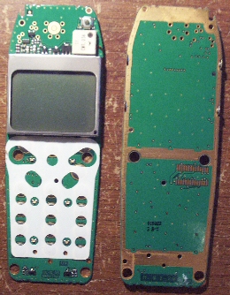
48x84, Small Graphic LCD w LED backlight.
 Clock Loop
Posts: 2,069
********************PROGRAM and SCHEMATIC UPDATED 01-20-06, LOOK AT LAST POST*****************
SX-B program available too.
84x48 Graphical Dot LCD's with Back L.E.D., and Useable Keypad. LCD is serially addressed using the SHIFTOUT command.
**NO WIRES**
http://forums.parallax.com/attachment.php?attachmentid=39336
----FRONT
BACK
Without Wires.
http://forums.parallax.com/attachment.php?attachmentid=39343
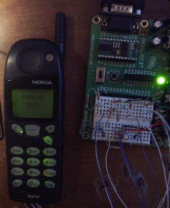
With Phone Case
http://forums.parallax.com/attachment.php?attachmentid=39342
This is in NO WAY an offer from anyone at parallax, they DO NOT offer support for these LCD's.
Programming help is offered here, from me! But these LCD's are so easy to use, I doubt you will need support.
If you have any questions, or want one, send me a Private Message.
For more info on the USE of the LCD Go here.
http://forums.parallax.com/showthread.php?p=555533
To get an idea of the size of the LCD, if you take 2 BS2 chips and put them side by side, the LCD is about that big.
They are not Big, but they are cheap, and can be used in PAIRS for larger viewing area.
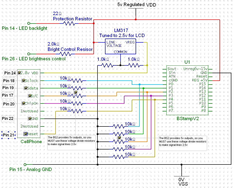
Attached is a program that will display "Parallax Rules" on your LCD when wired up like the attached schematic.
▔▔▔▔▔▔▔▔▔▔▔▔▔▔▔▔▔▔▔▔▔▔▔▔
Meh. Nothing here, move along.
Post Edited (BPM) : 6/1/2009 5:04:33 PM GMT


Comments
And in the end one big schematic to get all devices to work from as little as possible wires coming from the BS2. (using shift registers) 74hc595(serial in parallel out) & 74hc597 (parallel in serial out).
*** SCHEMATIC ALSO UPDATED TO INCLUDE POWER BUTTON, and BACKLIGHT.***
The program makes the LCD and LED turn off when you press the PWR button.
This brings the ampere draw to only 1.3ma in the OFF state.
In the ON state, the LCD and LED draw 70 ma, most of that being the LED, the LCD draws 2.8ma in the ON state.
***PROGRAM UPDATED 11-22-05 FOR BETTER KEY RESPONSE, NO MORE INCORRECT KEYPRESS DETECTIONS***
The keypad code and schematic is done.
Here...
The provided code will display what button is pressed in the very middle of the display. When you let up on the button, the display also clears.
The schematic uses a 595, and a 597(aka 165).
Post Edited (BPM) : 11/25/2005 3:00:50 PM GMT
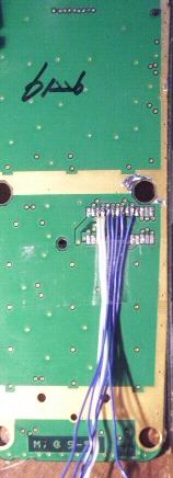
Heres a GIF that will tell you the proper pinout, this is a closeup of the connector.
And the definition of each pin:
Every BOLD item are the ones you will use to get the LCD light on, and the LCD working to display intro code “Parallax Rules” when running NokiaLCDv1.bs2
PIN - DESCRIPTION
K1 - ROW0 Keyboard matrix row 0
K2 - ROW1 Keyboard matrix row 1
K3 - ROW2 Keyboard matrix row 2
K4 - ROW3 Keyboard matrix row 3
K5 - ROW4 Keyboard matrix row 4
K6 - COL0 Keyboard matrix column 0, used for flip identification (i dont use this)
K7 - COL1 Keyboard matrix column 1
K8 - COL2 Keyboard matrix column 2
K9 - COL3 Keyboard matrix column 3
k10 - COL4 Keyboard matrix column 4
11 - Signal1 Flip interrupt, not used
12 - VF_IN Flash in
13 - VF_OUT Flash out
14 - VBATT Battery voltage 3.0-5.1V --- Provides 5v for back LEDs, Connect to regulated 5v thru 22ohm protection resistor!
This will allow 80ma max.
60 75 100 mA For lights
110min 300max mA For buzzer
15 - UAGND Analog ground 0 V ---GND
16 - PWRON Power on key --- PWR on button.
17 - D/C Command/Data -- D/C Data / Command mode.(DON’T EXCEED 2.8v, use schematic)
18 - SCLK LCD driver serial clock --- CLK, Clock line(DON’T EXCEED 2.8v, use schematic)
19 - SDA LCD driver serial data --- Data line (DON’T EXCEED 2.8v, use schematic)
20 - LCDCSX LCD CS driver chip select Low / Active connect to GND if not using.
21 - LCDRSTX LCD driver reset --- RESET (DON’T EXCEED 2.8v, use schematic)
22 - UDGND Digital ground 0 V -- GND
23 - BUZZER Buzzer PWM control 0 - 2.85 V
24 - VL Supply voltage 2.8V 300 uA -- Provide at least 2.5 volts REGULATED, DO NOT EXCEED 2.8volts
25 - SPARE Not used in UI
26 - LIGHT Illumination control --- Provide 5v here thru a 2kohm resistor for back LEDs
---IMPORTANT, DON’T USE SMALLER THAN A 1kohm brightness control.
This gives your back LED 65ma of power. Adjust resistor to increase or
decrease back led.
27 - EARN Speaker neutral 0 1.78 Vpp
28 - EARP Speaker positive 0 1.78 Vpp
A few tips for ya, use WIRE WRAP wire when your soldering to it. Its very thin and eaiser to keep it where you want it.
Test the connectors next to the wire you just soldered to see if you accidentally bridged them. (I did this and could NOT see it) Didn't notice untill I started having funny keypad problems.
If you can't get it the first 5 tries, keep trying. LOL. If you don't already have a desoldering pump, you might want to get one.
If you don't have one of those, you can get the solder off the connector by heating it up, and then QUICKLY hitting the circuit board on its side on the table to kinda force the solder to jump off the connector. To be sure, you can take a razor and run the edge between each connector point to clear out any bridged solder. (if its not alot)
Good Luck!
CAUTION His suggestion of using inertia to remove solder can be very dangerous to your eyes! I wear glasses and have many times over the years of desoldering used a similar method to remove solder from pins. I have also had to use my finger nail and alcohol to remove bits of flying solder and droplets of flux from my glasses. I may not like having to wear glasses, but I might have gone partially blind if not for my glasses due to flying molten solder(contact lenses don't count). Just think of how much that could hurt if it hit your cornea. Please remember to wear safety glasses whenever you solder especially if you do not wear glasses. It may seem like a nuisance but you only get one set of eyes.
I'm not saying "don't do it" just be aware that the molten solder can bounce and travel a ways before it hardens and cools. It might not be you that is hit, it could be your little brother/sister (son/daughter) or best friend that is watching you. Watch out for others around you as well. BTW, the same warning goes for grinding etc.
Learn from the mistakes and experiences of others, you don't have to make all the mistakes yourself, even if a mistake you make is ususally one of your best teachers.
Enough of my boring warning.
Happy New Year.
GREAT POINT! Thanks for posting this.
I have not, due to me not owning any of those phones. If one could get the data sheet on the phones in question, along with details on how the display is used, and or the keypad is used, then one could do exactly the same as I have done here.
With the right datasheets, you can re-hack almost anything. And remember by re-hacking, your recycling.
This circuit will soon be coded into assembly to be ported over to the SX line of microcontrollers. I just purchased the SX tech kit so it will take me a bit of time to learn the language and the cpu, but I WILL post the code and schematics to operate the keypad and lcd using the SX processor and assembly language.
Bean.
▔▔▔▔▔▔▔▔▔▔▔▔▔▔▔▔▔▔▔▔▔▔▔▔
"SX-Video·Module" Now available from Parallax for only $28.95
http://www.parallax.com/detail.asp?product_id=30012
"SX-Video OSD module" Now available from Parallax for only·$49.95
http://www.parallax.com/detail.asp?product_id=30015
Product web site: www.sxvm.com
"I hope the goonwave is not vaporware"
·
Heh, I am new to both, and I will prolly do it in both, or in SX/B and then see if I can understand/optimize the assembly.
▔▔▔▔▔▔▔▔▔▔▔▔▔▔▔▔▔▔▔▔▔▔▔▔
Meh. Nothing here, move along.
Post Edited (BPM) : 1/18/2006 6:11:14 PM GMT
Nice... One thing you do realize that you don't need to use "GOSUB" when you have declared your subroutines.
So where you have "GOSUB Display" you can just use "Display".
I think it makes it a little more readable. Like "Display" is actually a command.
Bean.
▔▔▔▔▔▔▔▔▔▔▔▔▔▔▔▔▔▔▔▔▔▔▔▔
"SX-Video·Module" Now available from Parallax for only $28.95
http://www.parallax.com/detail.asp?product_id=30012
"SX-Video OSD module" Now available from Parallax for only·$49.95
http://www.parallax.com/detail.asp?product_id=30015
Product web site: www.sxvm.com
"Ability may get you to the top, but it takes character to keep you there."
·
I think that the Electronic Goldmine is selling these [noparse][[/noparse]or something very similar] for $2.99 each.
▔▔▔▔▔▔▔▔▔▔▔▔▔▔▔▔▔▔▔▔▔▔▔▔
"When all think alike, no one is thinking very much.' - Walter Lippmann (1889-1974)
······································································ Warm regards,····· G. Herzog [noparse][[/noparse]·黃鶴 ]·in Taiwan
Post Edited (Kramer) : 1/18/2006 3:00:44 PM GMT
Heh, yeah, I only use GOSUB to help me realize that those are subroutines (and to help the pbasic dudes) I looked into the GOSUB command and it doesn't seem to take any more assembly space up. I took GOSUB out for the subs that pass variables to and fro (it requires that I remove it)
Attached is the same code above, but optimized ALOT. I made use of subroutine variable passing.
▔▔▔▔▔▔▔▔▔▔▔▔▔▔▔▔▔▔▔▔▔▔▔▔
Meh. Nothing here, move along.
I couldn't find any LCD's for 2.99.... The closest I found for that price, for a graphic LCD was some lcd with no pinout, or datasheet. I.E. totally useless.
These displays that I am offering are taken from cell phones. The displays are all the same, but are from similar cell phones.
▔▔▔▔▔▔▔▔▔▔▔▔▔▔▔▔▔▔▔▔▔▔▔▔
Meh. Nothing here, move along.
http://www.goldmine-elec-products.com/prodinfo.asp?number=G15611&variation=&aitem=65&mitem=103
Mike
▔▔▔▔▔▔▔▔▔▔▔▔▔▔▔▔▔▔▔▔▔▔▔▔
"OEM NMEA GPS Module" Now available on ebay for only $17.49
Product web site: http://www.allsurplus.net/Axiom/
As I see it, the only usefull part on that board is the LCD, not the keypad. And thats if the LCD is one that you can find out the pinout for it.
Or if you can HACK the connectors, and analyize them. (i could do it, but I have alot of the lcd/keypad's already and have no interest to get more)
Still the keypad is totally useless because you can't seperate it from the boards logic, nor does it come with the rubber like buttons that show the key label.
The boards I am offering also come WITH the cell phone case, and keypad. So it looks like a cellphone, i have found this usefull if you dont care what your projects interface looks like, you just what the display, and keypad input for cheap.
I use the cell phone/keypad as a hot plugged display / data input for robots, or various sx / bs2 circuits.
And actually I haven't even sold 1. But I don't care. I work a job. This is just a hobby. I was thinking of taking all my little displays (over 60 of them) and doing something massive with them.
MWAHAHAHA
▔▔▔▔▔▔▔▔▔▔▔▔▔▔▔▔▔▔▔▔▔▔▔▔
Meh. Nothing here, move along.
▔▔▔▔▔▔▔▔▔▔▔▔▔▔▔▔▔▔▔▔▔▔▔▔
http://www.paysonarizona.net/
Actually yes, I was going to make something out of the displays. And I still am, I just have more than I need, so I offered them here.
Plus I wanted the ability to make projects with small displays and keypads to enter commands etc.... I have already integrated a keypad and display housed in the original cell phone. Works great, and its compact compared to most other keypads and lcd's. I wear the thing, so I needed it smaller, and portable. I also don't want to mess with custom cases, so having the cell phone case with it works great too.
▔▔▔▔▔▔▔▔▔▔▔▔▔▔▔▔▔▔▔▔▔▔▔▔
Meh. Nothing here, move along.
I am glad I purchased the sx.
▔▔▔▔▔▔▔▔▔▔▔▔▔▔▔▔▔▔▔▔▔▔▔▔
Meh. Nothing here, move along.
The LCDs appear to be serial, which means minimal configuration. Even if the phone keyboard only provides a 12 button code, it all comes together as a nice interface for BasicStamps.
Goldmine also has complete cell phones [noparse][[/noparse]with the external case and the battery holder] for $6.99. Maybe that would be worth the case and the battery holder.
▔▔▔▔▔▔▔▔▔▔▔▔▔▔▔▔▔▔▔▔▔▔▔▔
"When all think alike, no one is thinking very much.' - Walter Lippmann (1889-1974)
······································································ Warm regards,····· G. Herzog [noparse][[/noparse]·黃鶴 ]·in Taiwan
If you used the SX to make a serial interface, then you would really have something.
In my opinion it's too much code for the stamp to send the dot pattern for each character. If you could just send text and have commands to turn pixels on/off and maybe to draw a line that would be cool.
Can you get more of the phone ? In my experience it's not worth selling a product unless you have 100 or more of them. But if you're doing it for the fun of it, then that doesn't really matter.
Bean.
▔▔▔▔▔▔▔▔▔▔▔▔▔▔▔▔▔▔▔▔▔▔▔▔
"SX-Video·Module" Now available from Parallax for only $28.95
http://www.parallax.com/detail.asp?product_id=30012
"SX-Video OSD module" Now available from Parallax for only·$49.95
http://www.parallax.com/detail.asp?product_id=30015
Product web site: www.sxvm.com
"Ability may get you to the top, but it takes character to keep you there."
·
IF you do decide to buy, MAKE SURE you buy only one at first, you might not be able to use the parts like you think.
If you can't find the datasheet for the LCD and or Keypad, 99% chance you won't get the lcd to work.
BTW, I am selling my cellphone cases, with keypad, and lcd for 5$.
▔▔▔▔▔▔▔▔▔▔▔▔▔▔▔▔▔▔▔▔▔▔▔▔
Meh. Nothing here, move along.
I prolly can get alot more of these. But I just don't think the demand is high enough to invest in. To make the cellphones usefull, adding a SX chip, with required support chips, and the board to solder it all too. The time to put it all together, and required equiptment.
After all is said and done, the time it took to solder the chips onto the board, the price for the pcb's, and the sx + support chip....
One would have to sell each cell-phone-hack for over 30$ to just break even. (keep in mind time - $$$)
I think I'd rather just offer the phone as is for 5$. It keeps the price low, and keeps me from having to invest my own time into a possibly dead end venture.
And I am only offering the phones because the pinout's, datasheets, and ALL required info to get it working, is fully available here and from me. (thats originally why I purchased over 60 of them)
▔▔▔▔▔▔▔▔▔▔▔▔▔▔▔▔▔▔▔▔▔▔▔▔
Meh. Nothing here, move along.
Thanks so much! I've had 4 in my desk for months wanting to interface them.
I even have the numbers 0 thru 9 if you want them.
▔▔▔▔▔▔▔▔▔▔▔▔▔▔▔▔▔▔▔▔▔▔▔▔
Meh. Nothing here, move along.
Anyone an idea?
Actually, after thinking of the way the code works, it looks like your display is damaged.
Unless the BS2 is going too fast for the LCD.... But I highly doubt that.
The only way you can test that is run this code..
It inserts a pause after every 8 bits clocked out.
I HIGHLY doubt that this is the problem.
The reason I say its a bad display, is because that kind of visual error is common of damaged circuitry or lcd lines.
I have seen alot of lcd's that are damaged and display stuff in even amounts.
For you, it displays every other line. Without knowing how the inner circuitry is wired inside the lcd theres no way for sure to tell if this
is a result of a bad display.
My personal guess is your lcd was already damaged.
Did you ever test it IN the cell phone? Or was the cell already dead?
▔▔▔▔▔▔▔▔▔▔▔▔▔▔▔▔▔▔▔▔▔▔▔▔
Meh. Nothing here, move along.