Shop OBEX P1 Docs P2 Docs Learn Events
Boe-Bot with Wireless ZipZaps Remote Control — Parallax Forums

Boe-Bot with Wireless ZipZaps Remote Control

Code MonkeyCode Monkey Posts: 26
edited 2007-08-10 14:49 in Robotics
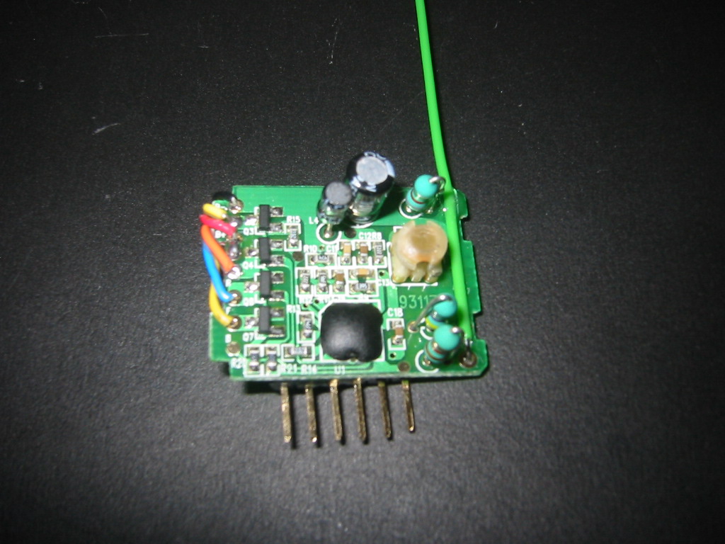
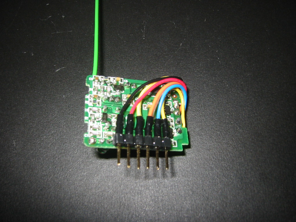
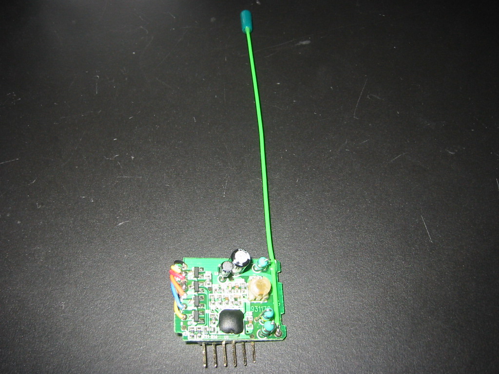
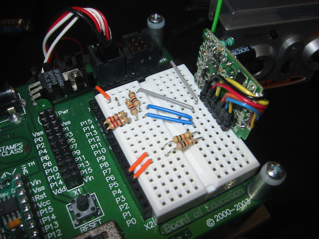
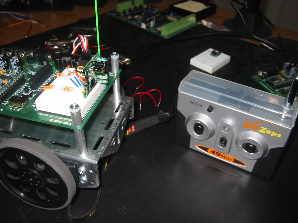
This is a pretty inexpensive way to add a remote control to your Boe-Bot. I took a Radio Shack ZipZaps remote controlled car and removed all of the car parts down to just the board. Then I wired the six important points to a six pin header which I epoxied to the back of the board. I also removed the flimsy wire antenna and replaced it with a solid breadboard wire which is re-enfored with a small amount of epoxy. This then can just plug right into the Boe-Bot board as a sort-of app mod. Now I can have my Boe-Bot chase the cats around the house with my ZipZaps remote control.
1024 x 768 - 200K
1024 x 768 - 258K
1024 x 768 - 249K
1024 x 768 - 248K
1024 x 768 - 200K
«1

Comments

  • Code MonkeyCode Monkey Posts: 26
    edited 2005-10-29 22:19
    Here's the basic code.
  • Robert@HCCRobert@HCC Posts: 80
    edited 2005-10-30 05:43
    Nice project, and thanks for sharing the great pics!

    I originally became involved with Parallax due to a college project I am involved in ( making CanSatellites) - but the more projects I see, the more I am getting sucked into robotics, lol.

    Now if I can just firgure out how to get a BOE-Bot outta our college funds instead of my fairly empty pocket!! haha

    Alohas
  • bulkheadbulkhead Posts: 405
    edited 2005-10-30 18:24
    Wow, what a great idea! I saw these Zip Zaps at my local RadioShack on clearance for around $12, so it is a really cheap way to add RC. Did you use a Zip Zaps SE or just the regular? If you did use the SE, did you take advantage of its digital proportional throttle?
  • Code MonkeyCode Monkey Posts: 26
    edited 2005-11-02 19:09
    This is one of the older ZipZaps from last year so there is no digital proportional throttle on this model. I am just using the forward/backward left/right digital indicators.

    -Marc
  • HavoKaneHavoKane Posts: 109
    edited 2005-11-08 17:11
    does it matter if it has the digital throttle?
  • Code MonkeyCode Monkey Posts: 26
    edited 2005-11-08 18:25
    It might. I'm not sure since I don't have one with the digital throttle.

    What I was able to figure out with my ZipZaps is this: The forward and back pins are both +V when neither of the buttons on the remote are being pressed. When you press either the forward or backward button on the remote, it's corresponding pin goes to ground. The left and right pins are not connected when neither button is pressed. When pressed the corresponding pin goes to ground.

    To detect the state of any of the buttons with the BS2 I just check for when the pin goes low. For the left and right controls this requires a couple of pull up resistors to keep the pins high when off like the forward and backward pins are normally.
  • MikeKMikeK Posts: 118
    edited 2005-11-10 00:12
    I picked up one of the $12.49 Zip Zaps (SE) from RS. It has proportional throttle and proportional steering. The throttle appears to work as previously described, except the voltage varies with how much the lever is moved off center.

    I don't have the proper instruments to figure out the steering. There's what looks like a pager motor that drives a tiny gearbox, which moves the wheels left or right. There's also a small potentiometer that looks like it is connected to the gearbox, and used for feedback on the position of the wheels (I'd have to destroy the car to see if it is connected for sure). I tried measuring with a VOM, but the voltage changes only briefly. My guess is that it pulses the steering motor until the pot indicates that the desired position is reached.

    There are also headlights and tail lights (2 x 2 LEDs). The headlights are lit when the car is going forward. The taillights are lit when the car is going backwards. There are 4 wires going to the lights: VCC, Ground, Headlights, Tail lights. VCC to Ground is about 3V (the NiMH battery is labeled 2.4V). The HL and TL wires are high, and are brought low to activate the respective lights. There's actually a small (0.25in x 0.5in ?) circuit board under the roof of the car's body that has 4 smd components on it. I didn't check if Ground for the lights is the same as the battery negative terminal.

    If anyone buys one, and you want to take the controller apart, you need to be aware of the following:
    1. The 4 screws in the back hold it together. Take the batteries out before you remove the screws.
    2. Before you can take the unit apart you have to remove the steering knob. It doesn't pry off. It's held on with a screw. There's a plastic dome over the screw, which is in the center of the knob. I pried the dome off with a pair of diagonal cutters. It might be possible to do it less destructively with a small screwdriver.
    3. The case might have to be gently pried out to clear the steering centering pot on the left side of the remote.
    4. The case might have to be pried up to clear the L/R switch on the top of the remote.
    5. The L/R switch has a small black piece of paper that fits over it. This might fall off when you open the case.
    6. The channel switch has a plastic cover. This will fall off when you open the case.
    7. There's a small spring that goes under the "release" button (there's a well in the back of the case to hold it). Guess what! This will also fall out.

    When taking the car apart, I found that if there's a screw, it has to be removed. Be careful around the front end of the car. There's a plate (with two small screws) that holds the front wheel assemblies in place. When you remove it two very! tiny springs may come off. Use caution.

    Hope this helps someone.
    Mike

    Post Edited (MikeK) : 11/10/2005 12:27:11 AM GMT
  • bulkheadbulkhead Posts: 405
    edited 2005-11-11 07:18
    Wow, thanks for the info MikeK.

    I guess its possible for digital proportional input through the forward/reverse controls by reading the voltage at the motor connectors. The steering system sounds to me much like how a servo works-motor is turned on/off/reverse based on potentiometer feedback. Any indications that the steering unit takes PWM?

    I may get one of these to play around with myself-I'll keep in mind those tips on opening it up.
  • MikeKMikeK Posts: 118
    edited 2005-11-11 15:54
    I can't really say for sure how the steering works (other than what I observed). The steering mechanism's travel is short (less than 0.25in) in either direction, so there's not a lot of time to measure what's going on. I don't have a storage scope. I didn't want to destroy the car (yet).

    It was worth the $13 (to me) when I opened the car and saw what they crammed in there. Plus, they're fun to play with.

    Sorry I couldn't be of more help.
    Mike
  • HavoKaneHavoKane Posts: 109
    edited 2005-11-26 00:39
    k, im on my way to radioshack now, what all do i need? just the 2x6 header, and C.M, can you write up kindofa how-to, or at least give a closeup pic of what wires are soldered where?
  • bulkheadbulkhead Posts: 405
    edited 2005-11-26 01:25
    Ok, I just got one of these (the SE for $12.49). They are fun to play with especially if you get two to race and set up a little course. I have to say, these are completely different from the original one. The wheelbase is longer (to accomodate the extra electronics). Also, the whole PCB with all the control circuits is covered in a rubbery-plasticky black coating, so it may be hard to solder on to the PCB directly. If the throttle is proportional, it's hard to tell, but the steering has many noticable steps. I don't want to take mine apart just yet, but when I do (probably in a few weeks), I'll post again.
  • Code MonkeyCode Monkey Posts: 26
    edited 2005-11-26 15:49
    HK,

    Again, this is from the first generation ZipZaps so your results may vary with the newer ones. But here goes...

    These pics are about as close up as I can get with my camera. If you look at the Close-up Front pic and starting from left to right lable the pins A-F here is what they connect to:

    A = Ground
    B = +5V
    C = Left
    D = Right
    E = Backward
    F = Forward

    Looking at the Close-up Back pic, the wires for A (Gnd) and B (+5V) are soldered to two connections which are labeled on my board as B- and B+. The others are soldered to the transistors which on mine are Q3, Q4, Q7 and Q8. So the pins are C=Q3, D=Q4, E=Q8, F=Q7.

    Hope this helps.

    -Marc
    1024 x 768 - 298K
    1024 x 768 - 301K
  • HavoKaneHavoKane Posts: 109
    edited 2005-11-27 00:05
    ok, so i have my zipzap, i have it apart, and im looking at the board, it looks the same as yours, even the serial number on the board. but it has some unshielded wires coming off of it that look like they go to the electromagnet that controls the steering. and it looks like your not using the last hole on the board that goes to the motor. and i dont see any abcdefg on my board either. is your serial 381178A? i dont see a letter at the end of your serial code, i think your antenna is blocking it.

    Post Edited (HavoKane) : 11/27/2005 12:31:58 AM GMT
  • HavoKaneHavoKane Posts: 109
    edited 2005-11-27 02:22
    damn $8 model. doesnt work. worked for a second when i took the batt out of the car and put it on the charger. it wont charge. i tested it with a multimeter, 3v out of the remote, dropts to .6v at the car. and to .06 at the batt. the light on the remote is supposed to be red when charging, and green when full. its green all the time.
  • HavoKaneHavoKane Posts: 109
    edited 2005-11-27 03:41
    yay, fixt
  • HavoKaneHavoKane Posts: 109
    edited 2005-11-27 06:06
    k, nvm, doesnt work, gonna return it and get one that works and start over
  • Code MonkeyCode Monkey Posts: 26
    edited 2005-11-27 07:36
    My serial number is 931178. Mine also had unshielded wires to control the steering. Also, the ABCDEF thing is not printed on the board... I was just using that as a way to indicate which pins on the front are wired to which holes on the back.
  • MikeKMikeK Posts: 118
    edited 2005-11-28 00:34
    bulkhead, the SE I've got definitely has proportional throttle. My 9 year old son can make it go various speeds. For me, it's basically off or too fast. smile.gif
  • PthagoreusPthagoreus Posts: 3
    edited 2005-12-24 14:24
    i have my Zipzap(SE) for about a year now it has been working good for awhile but i cant do a right turn now. I took it a part and some green and black thing fell off.(it was connected to the steering gearbox.)Do ineed it to steer or is it just the centering unit?
  • PthagoreusPthagoreus Posts: 3
    edited 2005-12-24 14:48
    I'll get picture of green and black thing asap
  • PthagoreusPthagoreus Posts: 3
    edited 2005-12-27 12:49
    i decided to abandon the ZpiZap with the broken green thing.· i bought a new Zipzap(SE) and when i put it on the charger, the light is amber and nothing is wrong.· Any body know something??????confused.gif
  • neotericneoteric Posts: 144
    edited 2006-02-25 13:39
    Finally got mine working, but wasn't happy with the range.· So I added a 3 ft. antenna.· REALLY helped with the range!

    Post Edited (neoteric) : 2/25/2006 1:48:11 PM GMT
    444 x 153 - 32K
    506 x 422 - 139K
  • Code MonkeyCode Monkey Posts: 26
    edited 2006-02-25 16:13
    Cool. I'm going to have to try adding a larger antenna to my Boe-Bot too.

    -Marc
  • Code MonkeyCode Monkey Posts: 26
    edited 2006-02-26 17:02
    Ok, now my bot has a large antenna and a little Florida bling bling too.
    1024 x 768 - 229K
    768 x 1024 - 89K
    1024 x 768 - 230K
  • Robert@HCCRobert@HCC Posts: 80
    edited 2006-07-20 12:16
    Ever since I saw this , I have wanted to try it out -
    Got my BOE bot last week, and finally had a chance to play this evening (well last evening now, heh) [noparse]:D[/noparse]

    Had picked up a ZipZap awhile back, in anticipation of trying this project out. Mine was a four wheel drive truck, and looked a little different than the original posted here. However, "F" ,"B","L","R",VSS and VDD were printed on one side of the pcb, so all looked good. I was kinda apprehensive about trying this at first, as my zipzap truck wasn't exactly working right to begin with - some times it worked, soemtimes it didnt. Found out why when I gutted it tho - the VDD wire practically fell out in my hand, lousy solder joint!.

    Anyways, I rewired and resoldered everything and to my extreme surprised, it actually worked! [noparse]:D[/noparse] Even have the little "board" with reverse lights and headlights working [noparse]:)[/noparse]

    Just one question tho- how do I make it STOP!! lol!

    Seems that it keeps on going, and going and gooooing until it gets turned off ( at the BOE Board) . Is this normal, or should it only move when I hit one of the sticks (like it does for the ZipZap vehicle) ? Although I am no where near the level of coder you are , Marc , it seems that in your code the values get zeroed out and it should stop until a button is pressed again right? or not?

    Either way, great project and an exceptional and easy way to add wireless control to the BoeBot. Thank you for sharing, its been a great learning experience - and I think will continue to be! I msut say, I am quite happy with my initial entry to robotics [noparse]:)[/noparse]

    Robert
  • Code MonkeyCode Monkey Posts: 26
    edited 2006-07-20 13:38
    Cool! Glad you got it working... It shouldn't keep running though. It should only move when you hold one of the buttons down. Which direction is it moving? The outputs may be a little different for your ZipZap vs. mine since mine was one of the original ones.

    -Marc
  • Robert@HCCRobert@HCC Posts: 80
    edited 2006-07-20 21:52
    It just continues moving depending on the last command it was given, if I hit reverse, it keeps reversing until I hit something else, Forward, backwards,etc...

    When I reset the stamp, all commands are cleared, but if I then push the stick for forward, it will go forward until I push the stick somewhere else.

    I am happy it works at all, and am sure as I learn more it will all work out. However, any input is appreciated!
    Thanks,
    Robert
  • Code MonkeyCode Monkey Posts: 26
    edited 2006-07-21 21:04
    Hmm... Maybe that has something to do with the digital proportional throttle on the newer ZipZaps. One of the other folks on this thread who got this working may be able to shed some light.

    -Marc
  • willthiswork89willthiswork89 Posts: 359
    edited 2006-07-22 20:58
    so did anyone get the steering to actually work with the SE? iver been everywhere looking for the original zipzap and no luck and i dont want to spend money on an se if i can only go forwards and backwards.... if you got the se to work please tell me so i can go buy it!
  • Robert@HCCRobert@HCC Posts: 80
    edited 2006-07-23 08:42
    The one I used was not the original - however, it was not the SE either. I can go forwards, backwards left and right - I just cant stop once started without cutting the power. The one I used was a four wheel drive truck ( since sold out at my radio shack location) that came in two models, a Chevy and Ford. Come to think of it, I think the Ford was a model of BigFoot.

    Besides the SE is only 12.00 or so, at that price a little experimentation is easily affordable - even if it doesnt work. I will probably fool with this more in the months to come, but first I have to finish my primary project [noparse]:D[/noparse]
Sign In or Register to comment.