Stamp controlled Laser Pointer
 Beau Schwabe
Posts: 6,576
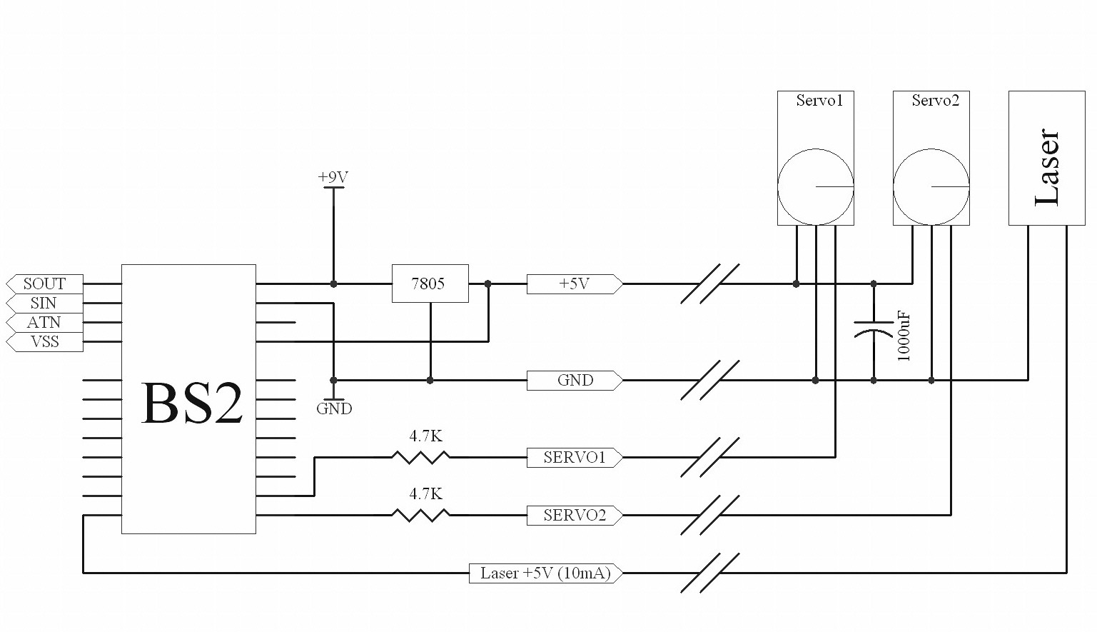
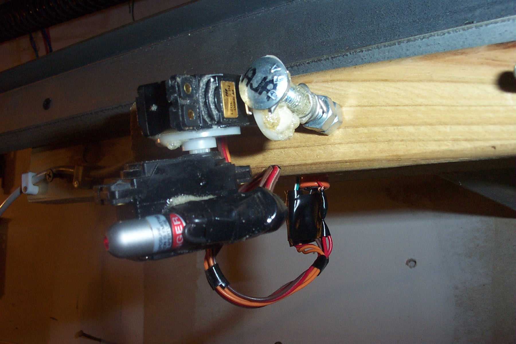
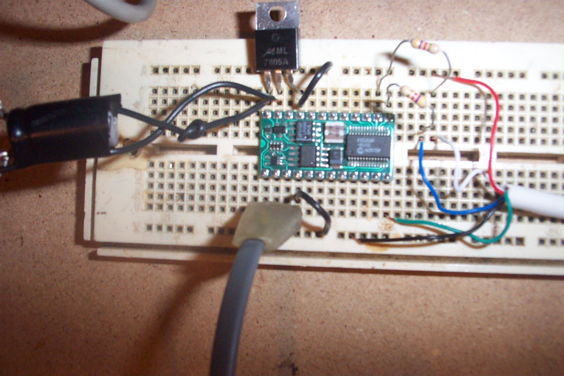
This is a project I started over the long weekend where a laser pointer is attached to two servo's in such a way that you
can control the X and Y location of the laser dot via a computer program.· Currently the test software is written for
QuickBasic which talks to a Stamp through the BS2 programming connector.· Eventually I will make a nice Visual Basic GUI.
·
The concept of tying a laser to two servos in this manor is to help me sort through my "wall" of parts bins.· The laser pointer
is located on an opposite wall about 9ft from the target (parts bins).· The idea, is that if I'm looking for a specific part I can
"search" for it with an attached computer and the laser pointer will point to the bin containing that part, providing I have told
the computer what is physically in that bin.· Other software options would be to sort, look for duplicates, show "empty bins",etc.
At 9ft away, I have about a centimeter resolution covering a wall span of 8ft wide by 5ft tall.
▔▔▔▔▔▔▔▔▔▔▔▔▔▔▔▔▔▔▔▔▔▔▔▔
Beau Schwabe
IC Layout Engineer
Parallax, Inc.
Post Edited (Beau Schwabe (Parallax)) : 9/6/2005 10:59:31 PM GMT


Comments
Now just add the emic to it : "Beau, I've found your part."
Ryan
▔▔▔▔▔▔▔▔▔▔▔▔▔▔▔▔▔▔▔▔▔▔▔▔
Ryan Clarke
Parallax Tech Support
rclarke@parallax.com
·· Hadn't you mentioned this project some time ago when someone mentioned a similar system using XYZ?
▔▔▔▔▔▔▔▔▔▔▔▔▔▔▔▔▔▔▔▔▔▔▔▔
Chris Savage
Parallax Tech Support
csavage@parallax.com
Yes, but it wasn't really formulated into something solid until last weekend. Before, I used something similar
with a super bright white LED and a few lenses from an old camera..... The laser works much better.
▔▔▔▔▔▔▔▔▔▔▔▔▔▔▔▔▔▔▔▔▔▔▔▔
Beau Schwabe
IC Layout Engineer
Parallax, Inc.
I wanted to build a laser scribbler!
Mount a couple of mirrors on each of the servo's (at 45deg angles??) and then have the stamp spell things on the wall....OR, what I was really after was using some red/green lasers and a smoke machine to make a tunnel effect!
Didn't get anywhere with it!! lol The hand laser pointers aren't really designed for continuous duty and I hadn't ventured much past the hardware design phase (I'm not so strong a programmer!)
Very neat though!
▔▔▔▔▔▔▔▔▔▔▔▔▔▔▔▔▔▔▔▔▔▔▔▔
·
Steve
"Inside each and every one of us is our one, true authentic swing. Something we was born with. Something that's ours and ours alone. Something that can't be learned... something that's got to be remembered."
is to go with precision high speed rotating mirrors.· Another solution would be to attach a rare
earth magnet to the back of a small (1cm square) mirror in addition to a "shirt pin" to be used
as the axel.· From here use a single or dual (differential) coil configuration to drive the mirrors.
Similar to an analog voltage meter only the coil(s) are stationary.
You can get away with using only one mirror if you have one servo directly·driving the other servo.
This is exactly what I did with the laser pointer in this design.··In the previous design I had the same
servo configuration only I used a mirror in place of the laser pointer.· For the light source, I used a
super bright white LED with a few lenses I borrowed from an old analog camera.· My focal distance
varied by about 1ft for a projection·distance of 9ft-10ft depending on the position.· I optimized the
pointer point for about 9.5ft and it worked out ok.·
▔▔▔▔▔▔▔▔▔▔▔▔▔▔▔▔▔▔▔▔▔▔▔▔
Beau Schwabe
IC Layout Engineer
Parallax, Inc.
The way some of those 'disco' lasers work is by mounting mirrors directly to speakers- the vibration of the speaker moves the mirror (which can be moved more slowly, to produce interesting light effects)-
Ryan
▔▔▔▔▔▔▔▔▔▔▔▔▔▔▔▔▔▔▔▔▔▔▔▔
Ryan Clarke
Parallax Tech Support
rclarke@parallax.com
Good Job Beau !
▔▔▔▔▔▔▔▔▔▔▔▔▔▔▔▔▔▔▔▔▔▔▔▔
There are 10 kinds of people....
Those who know binary and those who Don't.
Instead of a Joystick, here is a small Visual Basic test routine that uses the Mouse.
Turn the Laser "on" by pressing and holding the left mouse button.
The code in the BS2 is the same as above.
BTW) The dog as well as the cats, go nuts when trying to chase the laser dot
▔▔▔▔▔▔▔▔▔▔▔▔▔▔▔▔▔▔▔▔▔▔▔▔
Beau Schwabe
IC Layout Engineer
Parallax, Inc.
Gord
▔▔▔▔▔▔▔▔▔▔▔▔▔▔▔▔▔▔▔▔▔▔▔▔
·
Steve
"Inside each and every one of us is our one, true authentic swing. Something we was born with. Something that's ours and ours alone. Something that can't be learned... something that's got to be remembered."
Currently at 9ft away, the BEST resolution that I can get is about 1cm.
Assuming your laser will go 1 mile (5280ft), using my current setup, the divergence would be 344,178cm 586.7cm at 1 mile away from the laser.
divergence = ({distance in feet} / 9ft)^2
divergence = (5280ft / 9ft)^2
divergence = 586.7^2
divergence = 344178cm = 11291ft = 2.1miles
Edit: formulas above are wrong, they should read...
divergence = {distance in feet} / 9ft
divergence = 5280ft / 9ft
divergence = 586.7cm
divergence =·586.7cm = 231in = 19.25ft
▔▔▔▔▔▔▔▔▔▔▔▔▔▔▔▔▔▔▔▔▔▔▔▔
Beau Schwabe
IC Layout Engineer
Parallax, Inc.
Post Edited (Beau Schwabe (Parallax)) : 5/4/2007 10:06:09 PM GMT
▔▔▔▔▔▔▔▔▔▔▔▔▔▔▔▔▔▔▔▔▔▔▔▔
·1+1=10
It just seems funny that you need a clear sky to see clouds and yet you need enough particulate to be able to fire a laser up for guidance....
▔▔▔▔▔▔▔▔▔▔▔▔▔▔▔▔▔▔▔▔▔▔▔▔
·
Steve
"Inside each and every one of us is our one, true authentic swing. Something we was born with. Something that's ours and ours alone. Something that can't be learned... something that's got to be remembered."
▔▔▔▔▔▔▔▔▔▔▔▔▔▔▔▔▔▔▔▔▔▔▔▔
·1+1=10
▔▔▔▔▔▔▔▔▔▔▔▔▔▔▔▔▔▔▔▔▔▔▔▔
Chris Savage
Parallax Tech Support
csavage@parallax.com
http://forums.parallax.com/forums/default.aspx?f=15&m=122754
I hope I got this right ...
Thanks in Advance
Amaral
"...Seems like you are powering your BS2 by the Vin AND the Vcc..."
I am powering the project by Vin(pin24) and Vdd(pin23) ... I am paralleling the on-board 5V regulator with an external one.
"...another thing is in the comm part ( Sout , Sin , ATN , Vss ) there is NO Capacitors , do that works well without thouse ??..."
I am controlling the DTR pin directly in software to enable the Stamp. Otherwise, the Stamp will be in a perpetual reset mode.
▔▔▔▔▔▔▔▔▔▔▔▔▔▔▔▔▔▔▔▔▔▔▔▔
Beau Schwabe
IC Layout Engineer
Parallax, Inc.
That means that every meter the beam will spread by roughly 1mm.
1 kilometer would give you a spread of 1000*1mm or 1 meter.
A 75mW beam would still be visible with a spread of 5 meters so you'd be looking at a range of at least 5 kilometers.
I think we are referring to two different things. Your reference is to the divergence of the actual laser beam.
I am referencing the mechanical divergence caused by the limitations of the servo. At 9ft away with the particular
servo that I am using "1 servo tick" equates to the laser point on the wall moving by 1 cm.
Using the "Inverse Square Law" and normalizing it to 9ft = 1cm I came up with the formula below.
divergence = ({distance in feet} / 9ft)^2
At 9ft, the divergence would be 1cm
At 18ft, the divergence would be 4cm
At 4.5ft, the divergence would be .25cm
Expanding on this to 1 mile...
At 5280ft, the difference would be 344178cm or 2.1miles
Edit
Thinking about this further, the formula that I have is wrong.... I was making it more complex than it needed to be.
Using the "Inverse Square Law" is the wrong formula in this case.· If the "mechanical divergence" is 1cm at 9ft away, then at 18ft away it should be 2cm.
divergence = {distance in feet} / 9ft
expanding this out to 1 mile, the mechanical divergence would be 586.7cm· or about 19.25 feet ... in other words at 1 mile away, you could pinpoint something
within 19.25 feet based on the mechanical resolution of a standard hobby servo.
▔▔▔▔▔▔▔▔▔▔▔▔▔▔▔▔▔▔▔▔▔▔▔▔
Beau Schwabe
IC Layout Engineer
Parallax, Inc.
Post Edited (Beau Schwabe (Parallax)) : 5/4/2007 9:59:30 PM GMT
·I want to control·2 servos and a laser pointer·with a mouse and a BS2. Not connected to the PC.·Could this be easily done.··Would there·be·a schematic for the mouse wiring and a·code example·available ?
Thanks, RC
Post Edited (curious1) : 5/9/2007 2:21:19 PM GMT
Here is a program for the BS2 to emulate a standard serial Mouse...
http://webpages.charter.net/schwabelove/BasicStamp/MouStamp/
...It should not be difficult to turn this around so that it can "read" a serial mouse.
Once you are able to read a mouse, then you can either send out the appropriate commands to control the servo's.
Note: because of the overhead of reading a mouse vs. sending the servo pulse, this may require two stamps.
Alternatively you could explore the possibility of using a single Propeller IC. There are drivers in place that can already
read a mouse as well as control a servo.
▔▔▔▔▔▔▔▔▔▔▔▔▔▔▔▔▔▔▔▔▔▔▔▔
Beau Schwabe
IC Layout Engineer
Parallax, Inc.
▔▔▔▔▔▔▔▔▔▔▔▔▔▔▔▔▔▔▔▔▔▔▔▔
Chris Savage
Parallax Tech Support
I'm new to Basic and am just beginning to get comfortable with the BS2. The Mouse would not be practical for me at this point.
I will work with switches and a joy stick for now.
I will copy this info. to my workbook.
So much to learn....
Thanks again, RC
We must have submitted simultaneously. Could you expand slightly on your suggestion ?
I have the info. on SERIN and SEROUT in the manual .
PSC ???
Offload Servo Refreshing ???
Thank you,
RC
▔▔▔▔▔▔▔▔▔▔▔▔▔▔▔▔▔▔▔▔▔▔▔▔
Chris Savage
Parallax Tech Support
What do you think?
That sounds like a neat idea, but you would have to be careful with rain or snow.· Depending on the shape of your house you might only need one servo and just have it scan across the reflecting stuff
.· I bet it woul dlook much cooler with two lazers rather that one.· You could use red and green!!
▔▔▔▔▔▔▔▔▔▔▔▔▔▔▔▔▔▔▔▔▔▔▔▔
D Faust
You can get a simple but great display using a mirror mounted on with an angle on a pc fan. This video on youtube http://www.youtube.com/watch?v=YEMcgkAPCMU·uses a lab laser from http://www.dragonlasers.com·Can also be done with laser pointers but you have the duty cycle problem.
Oh yeah, if you do go into program writing, Pangolin is the best