

AD595 problems
 bhaan
Posts: 37
bhaan
Posts: 37
Can anyone tell me what I am doing wrong?
I am trying to read thermocouples with an AD595 thermocouple interface, then using the LTC1298 to convert the signal to digital data for the BS2.· The problem is that I am not getting consistent readings and sometimes the readings seem to be off.· I have spent some time looking thru old forums and other parallax data and have not been able to figure out why I can't get good readings.· I know that I probably did something wrong but I can't figure out what it is, does anyone have any ideas/suggestions?·
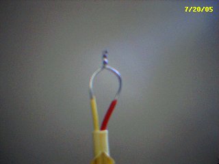
The code I used to read the LTC1298 is pasted below, I got the code from a parallax article I found.· The ADC can read 2 channels and I only need one, so I have just been ignoring the second reading.· The pdf attachment is my schematics, and the second is just a picture of the end of my thermocouple the way I understand to make them.· I should also mention that the circuit is wired up·on a breadboard (for testing purposes), if that matters.
Thanks,
Brian
'{$STAMP BS2}
'{$PBASIC 2.5}
·
·
CS············ CON······ 0
DIO_n·······CON······ 2
CLK··········CON······ 1
·config······· VAR······ Nib
AD··········· VAR······ Word
StartB······· VAR······ config.BIT0
sgIDif········ VAR······ config.BIT1
oddSign······VAR······ config.BIT2
msbf·········· VAR······ config.BIT3
·
HIGH CS
HIGH DIO_n
·
again:
· FOR oddSign = 0 TO 1
··· GOSUB convert
··· DEBUG "channel ", DEC oddSign,": ", DEC AD, CR
··· PAUSE 2000
· NEXT
· GOTO again
·
convert:
· config = config | %1011
· LOW CS
· SHIFTOUT DIO_n, clk, LSBFIRST, [noparse][[/noparse]config\4]
· SHIFTIN DIO_n, clk, MSBPOST, [noparse][[/noparse]AD\12]
· HIGH CS
RETURN
Post Edited (bhaan) : 7/20/2005 6:21:41 PM GMT
I am trying to read thermocouples with an AD595 thermocouple interface, then using the LTC1298 to convert the signal to digital data for the BS2.· The problem is that I am not getting consistent readings and sometimes the readings seem to be off.· I have spent some time looking thru old forums and other parallax data and have not been able to figure out why I can't get good readings.· I know that I probably did something wrong but I can't figure out what it is, does anyone have any ideas/suggestions?·
The code I used to read the LTC1298 is pasted below, I got the code from a parallax article I found.· The ADC can read 2 channels and I only need one, so I have just been ignoring the second reading.· The pdf attachment is my schematics, and the second is just a picture of the end of my thermocouple the way I understand to make them.· I should also mention that the circuit is wired up·on a breadboard (for testing purposes), if that matters.
Thanks,
Brian
'{$STAMP BS2}
'{$PBASIC 2.5}
·
·
CS············ CON······ 0
DIO_n·······CON······ 2
CLK··········CON······ 1
·config······· VAR······ Nib
AD··········· VAR······ Word
StartB······· VAR······ config.BIT0
sgIDif········ VAR······ config.BIT1
oddSign······VAR······ config.BIT2
msbf·········· VAR······ config.BIT3
·
HIGH CS
HIGH DIO_n
·
again:
· FOR oddSign = 0 TO 1
··· GOSUB convert
··· DEBUG "channel ", DEC oddSign,": ", DEC AD, CR
··· PAUSE 2000
· NEXT
· GOTO again
·
convert:
· config = config | %1011
· LOW CS
· SHIFTOUT DIO_n, clk, LSBFIRST, [noparse][[/noparse]config\4]
· SHIFTIN DIO_n, clk, MSBPOST, [noparse][[/noparse]AD\12]
· HIGH CS
RETURN
Post Edited (bhaan) : 7/20/2005 6:21:41 PM GMT

320 x 240 - 9K
Comments
▔▔▔▔▔▔▔▔▔▔▔▔▔▔▔▔▔▔▔▔▔▔▔▔
Tracy Allen
www.emesystems.com
I.
With 1.88Vdc applied to a single channel of the ADC, the reading my computer received was:
channel 0:· 1634
channel 1:· 1580
channel 0:· 1605
channel 1:· 1576
channel 0:··1603
channel 1:· 1578
channel 0:· 1655
channel 1:· 1583......
This really confuses me because I only applied the 1.88Vdc to one channel and both channels had a reading.· A zero reading would occasionally be shown too.
II.
when I put multimeter on the AD595, it consistently read about 4.7mV.· This confuses me too because the output should be 10mV/degree and this was measured at about 76 degF(24 degC).
V = 1580 * 1.2207 = 1.929
On the Stamp, you do that with the */ operator
milllivolts = AD */ 3125
DEBUG DEC millivolts/10, ".", DEC1 millivolts
The reason both channels follow along is that the input impedance is very, very high and their is a small amount of coupling between the channels.
The results are suspect. I'm not sure where to start. The AD reading with a 1.88 volt input should be about 1540 steps, but you were seeing higher than that on both channels. Which channel had the real input? Also, you are right, the output from the AD595 should be 10mV per degree. Was it grounded properly to your meter?
▔▔▔▔▔▔▔▔▔▔▔▔▔▔▔▔▔▔▔▔▔▔▔▔
Tracy Allen
www.emesystems.com
Now, another problem, I am trying to measure multiple thermocouples off of one AD595, so I have an ADG507 analog multiplexor.· I would like the thermocouples to connect to a terminal strip and then to the ADG507.· Can I use copper wire to connect from the terminal strip to the ADG507?· It is my understanding that you can do this if the connection points are at the same temperature, is that right?
I'm just learning so sorry if I'm way out of line but aren't the ends of the thermocouple supposed to be melted together ? It doesn't look like they are in the photo.
Larry
Post Edited (bhaan) : 7/25/2005 9:52:55 PM GMT
That is correct, but remember that even small temperature differences can have what may be an unexpected large effect. For example, if the terminals are on the outside of a box and there is a lamp or a body nearby, or a breeze, or a microprocessor heating up the inside of the box, you can easily add up a a couple of degrees of error. Arrange the system to keep everything at the same temperature (isothermal).
If you don't have it already, add a resistor of ~10 kohms or 1kohm to common (ADG507 common) on each leg of each thermocouple, where it attachs to the terminal at the input to the ADG507. That can reduce noise problems. When the ADG507 selects one thermocouple, the others that are not selected are still there and act as antennas to pick up AC hum and noise, which can be quite large and even overcome the common mode voltage of the mux chip. The resistors reduce the extraneous noise substantially. Shielding the thermocouples can also help. Also noise problems are much less if you can insulate the thermocouple tip from the body being measured, as direct contact means a bigger antenna.
▔▔▔▔▔▔▔▔▔▔▔▔▔▔▔▔▔▔▔▔▔▔▔▔
Tracy Allen
www.emesystems.com
It 's really important to keep this in a box at a uniform temperature. Don't load the output (either signal or alarm), because any power dissipation can create a temperature gradient that affects the result.
http://www.emesys.com/OL2therm.htm <--- thermocouple app note
▔▔▔▔▔▔▔▔▔▔▔▔▔▔▔▔▔▔▔▔▔▔▔▔
Tracy Allen
www.emesystems.com
First maybe I should explain what I am trying to do and maybe you will know of a better way to do it.· I am trying to read a total of 24 thermocouples with one of·the BS2 modules, 4 of the thermocouples should be able to read up to 2000 degF, and the other 20 only need to be able to read up to around 500 degF.· I was planning to do this by using AD595's and an ADG507 multiplexor.· I would be willing to buy something that is already on the market, but I have had trouble finding anything to interface to a BS2 and go up to 2000 degF.
I don't have much electronics experience, so the help I am receiving is much appreciated.
▔▔▔▔▔▔▔▔▔▔▔▔▔▔▔▔▔▔▔▔▔▔▔▔
Tracy Allen
www.emesystems.com
▔▔▔▔▔▔▔▔▔▔▔▔▔▔▔▔▔▔▔▔▔▔▔▔
Tracy Allen
www.emesystems.com
The reason I put one thermocouple in the fridge was just to give at least some variance to the temps, and I used a pot because the graphs of the thermocouple readings seemed to all·spike at the same time and I wanted to see if the pot would too.· I am wondering why my data looks like this, there is some event going on that is causing my data to almost offset, but the pot is unaffected for some reason.· One conecern I have is my Voltage Reference for my LTC1298, all I had was a 7805 regulator and a capacitor,·but I plan on using an LM336 when I am convinced things will work.·
The first chart is of all the channels and their mV reading, the second chart is of all the channels individually and it's pretty easy to see a major trend.· Another thing to note is that the pot and the first channel seemed to be the best, the spikes or the offset seemed to get worse in order of the channel being selected (1 had the smallest spike, and 8 had the biggest spike typically).· The second graph shows this, the pot is the bottom line, then channel one, then channel two(yellow) all the way up to 8.
I know there is a major trend here, but what is causing this?· Is it as simple as my reference voltage?· I'll attach a schematic later this afternoon.
Post Edited (bhaan) : 8/4/2005 8:02:31 PM GMT
The layout of the circuit and the shielding are all important. The power supply has to be well filtered with no ground loops under the signal path. One thing I notice is a _12_ volt input supply (wall wort?) and a _15_ volt regulator.
▔▔▔▔▔▔▔▔▔▔▔▔▔▔▔▔▔▔▔▔▔▔▔▔
Tracy Allen
www.emesystems.com
Here is the same test, with 7 thermocouples at room temp,·1 in the fridge, only there's no pot in this one.· All I changed was I added a 10k Ohm resistor from pin 14 to ground, there was one already from pin 1 to ground.· The data looks pretty good but still has small consistent·spikes.
One more question, what is the best way to read up to 2000 degF?· Should I use a pot as a voltage divider·before my LTC1298?· I saw on an eme systems article (http://www.emesystems.com/OL2therm.htm) that you can put a resistor between pin 5 and 9.· Do you loose alot of accuracy by putting a resistor between 5 and 9?· Wouldn't it be better to have the AD595 on a 15 volt supply and scale its output with a pot?
Post Edited (bhaan) : 8/5/2005 9:46:20 PM GMT
You might try the following things to help reduce noise.
LTC1298:
1. Add a .1mfd from the CH1 input(potentiometer) to ground.
2. Try grounding CH1 and see if CH0 cleans up.
2. Add a 1 mfd tantalum capacitor from V+ to ground. The spec sheet mentions this.
AD595:
1. Add a .1mfd bypass capacitior from V+ to ground.
Dave
By ground loop, I mean something like the following. Suppose you connect the resistor from pin 1 to ground point A, and the resistor from pin 14 to ground point B that is located two inches away on the prototyping board. Now suppose there are currents flowing in the circuit, to power the Stamp and all the other stuff. Due to those currents, which fluctuate with time, the voltage at ground point A is not exactly the same as the voltage at ground point B. A might be a couple of millivolts different. Not much, but that is a huge difference when it appears at the input of the AD595 amplifier. Therefore, it is important that those two resistors be connected to the same ground point, with no "ground loop" between them.
Also, suppose that one of the resistors is connected to the ground point directly, with very short leads, while the second one is connected via a loop of wire that runs parallel to the power line for the BASIC Stamp or near the wall wort power supply. That lead will pick up voltages from the CPU power line or from the AC power line or from a nearby radio tower. The first resistor does not pick up those signals, so the difference appears as a signal in your AD595 amplifier, and then as noise in your thermocouple readings. Those two resistors need to be wired with care and concern for ground loops and noise pickup. Also be careful with the ground connections for the multiplexer and the AD595. Analyze your whole circuit layout with concern for those issues! Bypass capacitors are a part of this issue. Be sure there are good bypass capacitors right near the digital circuitry and the power supply. You don't want the power currents to have to come back all the way across the circuit board to pass through bypass capacitors near the analog circuitry! That situation can lead to bad behavior! Allways know where your currents are hanging out!
As it stands, you have all the thermocouples attached to the inputs of the AD607 multiplexer, operating on a power supply of 0 and 15 volts. (I am not familiar with that mux, but I think you could also operate it off of a lower supply voltage, or off of a split supply.) The input common mode voltage is zero volts. When a thermocouple is selected, it is connected through to the AD595 input, where the 2 10kohm resistors enforce a common mode voltage of zero. That leaves 7 thermocouples unselected and floating with respect to ground. I don't know if the following is happening in your system, but it _can_ happen when the thermocouples are long or when they are attached to large conductive bodies. They act as antennas and pick voltage from the AC lines, and especially insidious signals from nearby radio towers and switching power supplies. Those signals are large enough to be detected by the substrate diodes on the mux chip, and all bets on the interchannel isolation are off. The AC signals feed through into the selected channel. There are things you can do to lessen that effect. One is to put 10kohm resistors and 0.1uf X7R bypass capacitors to ground on both sides of each and every thermocouple at the input side of the mux. The pickup is usually a common mode signal, but putting bypass on both sides prevents it from becoming differential. Another help is to use split supplies for the mux, or some other scheme to move the common mode voltage away from the mux Vss supply. That makes the bad signals less likely to turn on the substrate diodes, as the signal has to reach a higher level to do so.
As to the measurement at 2000 degrees F (1093 degC). The resistor from pin 5 to pin 9 is a good solution, well within the accuracy of thermocouples. The resistor simply reduces the gain of the amplifier below the nominal 10 millivolts per degree Celsius. You might want to make it 4 millivolts per degree Celsius. When looking at a large temperature range, you may need to take into account a linearity correction.
Have you also considered using the Maxim direct to digital thermocouple chips? (MAX6675). That woud avoid a lot of your analog design problems.
▔▔▔▔▔▔▔▔▔▔▔▔▔▔▔▔▔▔▔▔▔▔▔▔
Tracy Allen
www.emesystems.com
The first thing I did when I started this project was get some MAX6675's because I read your article and they were very easy to use(especially after reading your article).· One thing I found out later though was that I had to read up to 2000 degF(1093 degC), and I beleive the MAX6675 can only read up to 1875 degF(1024 degC).··Is there any way to read up to 2000 degF with the MAX6675?· Since I have to read 24 thermocouples do·they each need their own bypass capacitor?· I would rather use the MAX6675's in order to cut out all the analog worries I have.
Your adivce is very helpful and much appreciated.
Post Edited (bhaan) : 8/9/2005 1:10:16 PM GMT