

PropBASIC INA226 - stuck on I2C
 hatallica
Posts: 180
hatallica
Posts: 180
I find myself stuck on a new project involving INA226. I started with an I2C library. When that did not work as expected, I dove into the datasheet and manually wrote the standard commands.
Below is a simple test that should return a known value (power-on reset value of the config register is $4127). However, the output to the terminal shows every bit high.
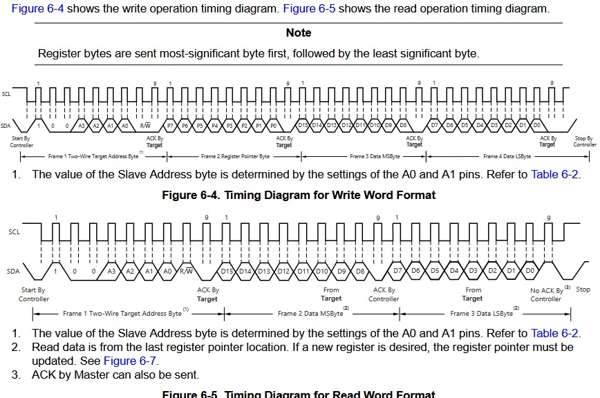
Below that is the timing diagram from the datasheet that I am trying to emulate. Does the code accomplish this, or is my understanding flawed? I have checked and double-checked pin connections (breadboard prototype), but will probably tear it apart and do it again to be certain. Any guidance is greatly appreciated.
I2C_SDA     PIN   29    LOW         ' I2C for EEPROM and peripherals; no external access
I2C_SCL     PIN   28    LOW         ' I2C for EEPROM and peripherals; no external access

TERMINAL_NUMBER SUB     1   ' send number to debug terminal

' ======================================================================
  PROGRAM Start LMM
' ======================================================================
' LMM allows larger code at the expense of running slower
'   NOTE that I2CSPEED >2 does not work in LMM (>7 may or may not work at all)
'  I2CSPEED 2      ' floating point parameter (i.e. both 0.5 and 2 are valid)

Start:
    I2CSTART I2C_SDA, I2C_SCL
    I2CWRITE I2C_SDA, I2C_SCL, $40  ' Device address for write
    I2CWRITE I2C_SDA, I2C_SCL, $00  ' Config register
'    I2CWRITE I2C_SDA, I2C_SCL, $41  ' config value - msb
'    I2CWRITE I2C_SDA, I2C_SCL, $27  ' config value - lsb
    I2CSTOP I2C_SDA, I2C_SCL

    PAUSE 100   ' not sure if this is needed

' *** Read data is for the last register pointer location.
    I2CSTART I2C_SDA, I2C_SCL
    I2CWRITE I2C_SDA, I2C_SCL, $41  ' Device address for read
    I2CREAD I2C_SDA, I2C_SCL, idx, 0    ' read byte
    I2CREAD I2C_SDA, I2C_SCL, idy, 1    ' read byte, no ack
    I2CSTOP I2C_SDA, I2C_SCL

    TERMINAL_NUMBER idx     ' convert to ascii string and display value on terminal
    TERMINAL_NUMBER idy
END

' ----------------------------------------------------------------------
' SUB/FUNC Code
'   If routines are nested, then verify that __paramx variable values are unique
' ----------------------------------------------------------------------

' Use: TERMINAL_NUMBER param1
' --- param1 = value to convert to string for display on serial terminal
'{$IFUSED TERMINAL_NUMBER}
SUB TERMINAL_NUMBER
    ascii = STR __param1, 10  ' convert value to string of digit number
    ascii = ascii + 13  ' add carriage return manually
    SEROUT TX, T115200, ascii
ENDSUB      ' --- TERMINAL_NUMBER
'{$ENDIF}
Comments
Do you have pullup resistors on the I2C pins?
Not sure if this answers my own question, but I found evidence that I goofed. Looking at JonnyMac's object for the similar INA219, it appears that I misunderstood the Read portion (no need to stop between pointing to the register and reading it). When I get home, I will try the following.
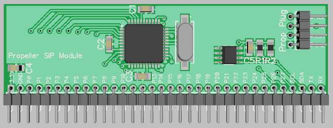
Start: I2CSTART I2C_SDA, I2C_SCL I2CWRITE I2C_SDA, I2C_SCL, $40 ' Device address for write I2CWRITE I2C_SDA, I2C_SCL, $00 ' Config register ' *** Read data is for the last register pointer location. I2CSTART I2C_SDA, I2C_SCL I2CWRITE I2C_SDA, I2C_SCL, $41 ' Device address for read I2CREAD I2C_SDA, I2C_SCL, idx, 0 ' read byte I2CREAD I2C_SDA, I2C_SCL, idy, 1 ' read byte, no ack I2CSTOP I2C_SDA, I2C_SCL TERMINAL_NUMBER idx ' convert to ascii string and display value on terminal TERMINAL_NUMBER idy ENDThe INA226 module PCB has 10Kohm pull-ups. My P1 prototyping board has pull-ups also, but I forget the values. This was an early draft, but R1 and R2 are already shown.
Ok, it's a common mistake to leave them off, so thought I'd ask...
Also, is the eeprom on the same I2C bus?
Regardless, you could try working with that to see how code should be...
Looks to me like the first part needs to match:
Figure 6-7. Typical Register Pointer Set
Looks like it might need a stop after sending the register#
Also, looks like your device address might be wrong... Looking at this table:
Table 6-2. Address Pins and Slave Addresses
Appears first nibble in address should be $8 or $9 ...
Ultimately, Table 6-2 is what tripped me up, so I appreciate being challenged on that. It shows 7 bits, so I wrote the ID as %100_0000.
In reality, it should be %1000_000_ ... then the R/W bit.
The example code (other languages) I could find defined the address $40, but they must have shifted the bits elsewhere.
I tested by reading the config register ($00) and the die ID ($FF), getting the expected result both times. Below is reading the Bus Voltage, which also returned a valid result. Time to clean it up and integrate it into the rest of the program!
' ====================================================================== PROGRAM Start LMM ' ====================================================================== ' LMM allows larger code at the expense of running slower ' NOTE that SPI code may hang if both LMM and PLL<8X ' NOTE that I2CSPEED >2 does not work in LMM (>7 may or may not work at all) I2CSPEED 2 ' floating point parameter (i.e. both 0.5 and 2 are valid) Start: ' *** Consider die ID check for INA226 to validate population and operation I2CSTART I2C_SDA, I2C_SCL I2CWRITE I2C_SDA, I2C_SCL, $80 ' Device address for write I2CWRITE I2C_SDA, I2C_SCL, $02 ' Bus V register ' *** Read data is for the last register pointer location. Should not require updating. I2CSTART I2C_SDA, I2C_SCL I2CWRITE I2C_SDA, I2C_SCL, $81 ' Device address for read I2CREAD I2C_SDA, I2C_SCL, idx, 0 ' read byte I2CREAD I2C_SDA, I2C_SCL, idy, 1 ' read byte, no ack I2CSTOP I2C_SDA, I2C_SCL idx = idx <<8 idx = idx + idy TERMINAL_NUMBER idx ' convert to ascii string and display value on terminal ENDAnd finally ... confirming that there was also no issue using the ubiquitous I2C library. It was all simply a bit-shift goof. Capturing for posterity. At least this exercise forced me to learn a bit more about the inner-workings of I2C.
** full disclosure - these snippets are obviously missing definitions for pins, variables, constants, etc. **
LOAD "Libraries\I2C_LIB.pbas" WRITE_INA226 SUB 2 ' pass register location and value to be written READ_INA226 FUNC 1 ' pass register location and return value ' ====================================================================== PROGRAM Start LMM ' ====================================================================== ' LMM allows larger code at the expense of running slower ' NOTE that SPI code may hang if both LMM and PLL<8X ' NOTE that I2CSPEED >2 does not work in LMM (>7 may or may not work at all) I2CSPEED 2 ' floating point parameter (i.e. both 0.5 and 2 are valid) Start: ' *** Consider die ID check for INA226 to validate population and operation idx = READ_INA226 REG_DieID ' test with standard i2c library IF idx = VAL_DieID THEN TERMINAL_NUMBER idx ' convert to ascii string and display value on terminal ELSE TERMINAL_NUMBER $00 END ENDIF idx = READ_INA226 REG_Config ' test with standard i2c library TERMINAL_NUMBER idx ' convert to ascii string and display value on terminal WRITE_INA226 REG_Calib, VAL_Calib idx = READ_INA226 REG_Calib ' test with standard i2c library TERMINAL_NUMBER idx ' convert to ascii string and display value on terminal WRITE_INA226 REG_Limit, VAL_Limit idx = READ_INA226 REG_Limit ' test with standard i2c library TERMINAL_NUMBER idx ' convert to ascii string and display value on terminal idx = READ_INA226 REG_BusV ' test with standard i2c library TERMINAL_NUMBER idx ' convert to ascii string and display value on terminal END ' ---------------------------------------------------------------------- ' SUB/FUNC Code ' If routines are nested, then verify that __paramx variable values are unique ' ---------------------------------------------------------------------- ' Use: TERMINAL_NUMBER param1 ' --- param1 = value to convert to string for display on serial terminal '{$IFUSED TERMINAL_NUMBER} SUB TERMINAL_NUMBER ascii = STR __param1, 10 ' convert value to string of digit number ascii = ascii + 13 ' add carriage return manually SEROUT TX, T115200, ascii ENDSUB ' --- TERMINAL_NUMBER '{$ENDIF} ' ---------------------------------------------------------------- ' ' --- I2C INA226 WRITE --- ' set all parameters due to shared I2C lines ' * Shell for INA226 specific write settings ' * Must provide param1=register and param2=value to be written '{$IFUSED WRITE_INA226} SUB WRITE_INA226 Register_Address = __param1 ' passed register address location Control_Byte = Wr_INA226 ' INA226 device address Address_Len = 1 ' INA has byte address (like $07) I2C_Out __param2, 2 ' writes 2 bytes to Register_Address (word or <65,536) ENDSUB '{$ENDIF} ' ---------------------------------------------------------------- ' ' ---------------------------------------------------------------- ' ' --- I2C INA226 READ --- ' set all parameters due to shared I2C lines ' * Shell for INA226 specific read settings ' * Must provide the param1=register. Returns the value in that register. '{$IFUSED READ_INA226} FUNC READ_INA226 Register_Address = __param1 ' passed register address location Control_Byte = Wr_INA226 ' INA226 device address Address_Len = 1 ' INA226 has byte address (like $07) __param1 = I2C_In 2 ' reads 2 bytes into param1 (word or <65,536) RETURN __param1 ENDFUNC '{$ENDIF} ' ---------------------------------------------------------------- 'You'll see this in Arduino-compatible code. Internally, their library shifts that left by one bit to make space for R/W.
/*
 * Function twi_slaveInit
 * Desc     sets slave address and enables interrupt
 * Input    none
 * Output   none
 */
void twi_setAddress(uint8_t address)
{
  // set twi slave address (skip over TWGCE bit)
  TWAR = address << 1;
}
The first I2C component I ever worked with (long before the Arduino was around) was an EEPROM and its datasheet showed the full 8 bits (including RW) of the device ID, so I've always used that style in my code. In my Spin I2C scanner I show detected devices in 8- and 7-bit modes to help myself and others when looking at examples from elsewhere.