@Rayman said:
Definitely roomy with the double width enclosure...
nice. yes. that would allow use in the triple and quadruple width connection boards.
any chance it would fit usefully on a 15 terminal wide one? that would also accommodate the 2/3/4 wide boxes.
the 15 wide box would allow some larger connector blocks that don't fit in the single-wide bay of the others. but wouldn't preclude the double wide box https://www.digikey.com/en/products/detail/bud-industries/DMB-4775/8602401
@refaQtor
The DMB-4775, 15 terminal size does look like a better fit for the box I'm making...
Didn't get it because wasn't in stock at Digikey. But, see they have it Mouser...
Not sure how that 2x4 RJ45 would fit in these...
Are you thinking of coming out the side with this on middle board?
@Rayman said:
Not sure how that 2x4 RJ45 would fit in these...
Are you thinking of coming out the side with this on middle board?
I was thinking two separate boards on the bottom, one for each side. feed the PCB through from the outside, leaving the double-high connector block fully outside the box. 2x4 rj45 on one side , perhaps, and relay connectors or different on the other side potentially. but, two separate sides to mix/match. the 15 terrminal wide box is enough to have room for the essential two terminal power in connector for 12-24V expected around a DIN rail.
@Rayman said:
Think the 5V supply for P2 needs to be isolated from 24V control supply?
Thinking not...
Not needed but it is a normal ruggedisation step. Something like USB/comports would share the processor's ground. Best not to have the 24 volts commoned to the comms.
That said, my stepper boards have no isolation at all. Instead I use protective TVS zenors and series PTC thermistors on the data lines. So it's certainly not compulsory to fully isolate.
maybe I shoulda said top/bottom (when mounted on a horizontal din rail) instead of "side"
I don't think anything other than some pin header bus- meant to gang these together- should be accessible from the side.
sorry, this is what I had in mind.
all the pin connections remain inside the box. clearly, this board can only be half width, because the PCB would have to slide in from the outside.
@refaQtor The P2 obviously doesn't have that many I/O pins for 8X RJ45. Are you thinking of using the same P2 I/O pins for several connectors? Or, using unipolar signaling with 1 side of each twisted pair being ground, meaning only 4 P2 I/O for each port?
@refaQtor said:
sorry, this is what I had in mind.
all the pin connections remain inside the box. clearly, this board can only be half width, because the PCB would have to slide in from the outside.
That's not mandatory, if you clip the thin rail, you can insert the board from below.
You need just a each-corner lip to locate the board, so the whole thin terminal rail can be removed ( or lowered) if you want.
@Rayman said:
@refaQtor The P2 obviously doesn't have that many I/O pins for 8X RJ45... meaning only 4 P2 I/O for each port?
I've been using 4 I/O for each RJ-45 : 1pair for (usually) 5V, 1 pair for ground (power and ground pairs match the PoE pinout), usually just using 1 twisted pair for RX/TX , usually just short range TTL. I have hooked up RS-485 to send over the rx/tx pair - just sending ASCII at the moment, though I expect to use RS-422 that'll use up 2 pair of rx/tx. Two pins are usually unused, but I have used them to signal wake/sleep signals to the devices at the other end.
usually, the devices at the other end are other micros, usually arduini or Linux on a BeagleBone. and usually simple ASCII. I have a database console on the Beagle, and usually the arduini are assorted gas sensors (usually just spewing simple readings at 1 second rate) that I reconfigure frequently at the end of their ethernet patch cables into different positions in gas tubing. and I never have to touch the code... when the data from multiple serial connections get agregated with their port numbers prepended, it all routes up to live plots on the desktop. and log files - the data source us sorta self-documenting.
So far it has been a jangle of dupont-wire interconnects to bulkhead jacks on the P2 side and perf-boards with female headers with common key Serial port pins routed to RJ-45 connector. the female headers match, so far, the Arduino Pro and the the "Feather" boards, and they get snapped into old wall surface mounted RJ45 network jack boxes.
the commonality is becoming apparent and I'm able to knock these together pretty quick. But, I'm beginning to capture the schematics and layout some common boards to make the process quicker, cleaner, more robust and secure. But, life is just happening hard and I still just go with it as it is for, probably, a few more months. though, each new one reveals another common element.
lots of nice stuff happening on the visualization and user interface front, so that''ll be nice to incorporate too, when the time comes.
maybe there are some ideas in there that'll be useful for your efforts. But, please don't go off in the weeds trying to follow what I'm still conjuring up - I tend to have pretty un-orthodox directions for the whole thing. Do what makes sense for you and your project. I don't want anyone else making my mistakes for me.


Comments
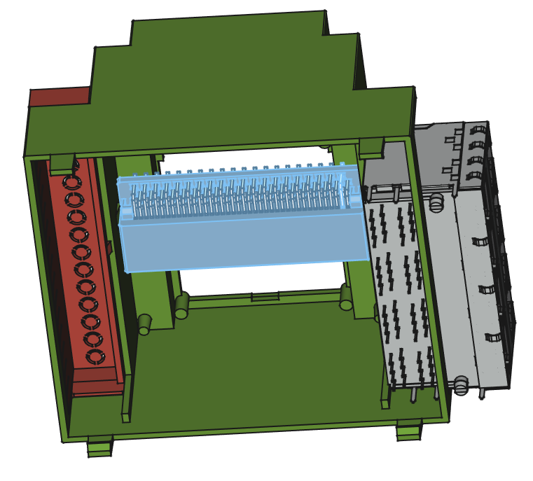
Connections between boards looks not as easy as thought...
It is 0.197" between top and middle boards and 1.134" between middle and bottom boards.
nice. yes. that would allow use in the triple and quadruple width connection boards.
any chance it would fit usefully on a 15 terminal wide one? that would also accommodate the 2/3/4 wide boxes.
the 15 wide box would allow some larger connector blocks that don't fit in the single-wide bay of the others. but wouldn't preclude the double wide box
https://www.digikey.com/en/products/detail/bud-industries/DMB-4775/8602401
as I'd mentioned, if I can't get the 2x4 RJ45 connector block, I'll have to make my own P2 board for the middle board.
which is OK, too. just thought I'd mention.
https://www.digikey.com/en/products/detail/same-sky-formerly-cui-devices/CRJ036-5-TH/14322828
Found some headers that can bridge the large gap:
I'm likely to have odd requirements on which pins go up and down between the boards, too.
So, don't think too hard about it.
yep, I thought I'd sent link to those. I got a batch for my own testing. curious to see the EMI issues from them.
@refaQtor
The DMB-4775, 15 terminal size does look like a better fit for the box I'm making...
Didn't get it because wasn't in stock at Digikey. But, see they have it Mouser...
Not sure how that 2x4 RJ45 would fit in these...
Are you thinking of coming out the side with this on middle board?
I was thinking two separate boards on the bottom, one for each side. feed the PCB through from the outside, leaving the double-high connector block fully outside the box. 2x4 rj45 on one side , perhaps, and relay connectors or different on the other side potentially. but, two separate sides to mix/match. the 15 terrminal wide box is enough to have room for the essential two terminal power in connector for 12-24V expected around a DIN rail.
but, I tend to go overboard on my flexibility in design. so, don't hold up your fantastic progress to accommodate my odd fantasy.
Not sure if there will be enough space on the sides for my particular project, but maybe...
Can try to be accommodating for that option at least...
Think the 5V supply for P2 needs to be isolated from 24V control supply?
Thinking not...
Not needed but it is a normal ruggedisation step. Something like USB/comports would share the processor's ground. Best not to have the 24 volts commoned to the comms.
That said, my stepper boards have no isolation at all. Instead I use protective TVS zenors and series PTC thermistors on the data lines. So it's certainly not compulsory to fully isolate.
See this doesn't have the magnetic isolation in it. Probably a good thing...
Was wondering how RS232 was going to work with magnetics..
Thinking most of my I/O needs are 24 VDC. To that end, plan is to use these ORMOM signal relays on bottom board. They are relatively tiny and offer pretty good protection:
https://www.digikey.com/en/products/detail/omron-electronics-inc-emc-div/G6K-2F-DC3/512430
There are these 3 V ones for output and also 24 V ones for input.
right. no. just using the physical connector, not driving ethernet over it.
Here's the middle board with smt version of PLC84 on DMB-4775.
Not a whole lot of room, but maybe enough...
Looks like Edge module could fit in there too...
At least on board, not sure about in the box...
@refaQtor That 8X Rj45 is too big to fit in these... At least on middle board... I'll see if a 4X can fit...
Wow, just noticed the P1 Wikipedia page shows a ladder logic program...
Looks a lot like ldmicro to me.
Should mean the source code is around somewhere...
And if can output Spin1, maybe not so hard to make it output Spin2.
Actually, P1 might be enough for a lot of things, so this could be interesting...
Not a lot of room in DMB-4775. Maybe can get in dual RJ45 and dual USB.
Have to be concerned with interfering with stuff on bottom board too...
maybe I shoulda said top/bottom (when mounted on a horizontal din rail) instead of "side"
I don't think anything other than some pin header bus- meant to gang these together- should be accessible from the side.
sorry, this is what I had in mind.
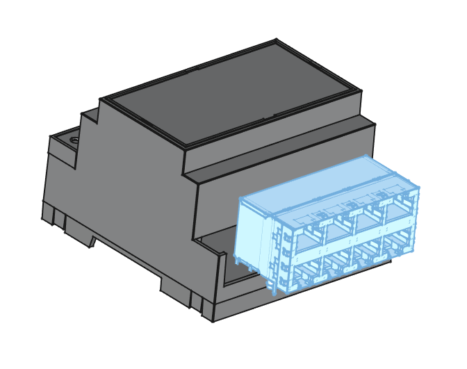
all the pin connections remain inside the box. clearly, this board can only be half width, because the PCB would have to slide in from the outside.
@refaQtor Ok, I see... You want replace the I/O headers on one side with this. Guess that would mean mounting to the bottom PCB.
I'll take a look at that, but need a lot of terminals...
By my count, need:
4: 24VDC input power
4: Inputs
7: Outputs
Not sure counting everything yet...
There are 15 terminals on each side.
So, maybe something like 4X RJ45...
@refaQtor The P2 obviously doesn't have that many I/O pins for 8X RJ45. Are you thinking of using the same P2 I/O pins for several connectors? Or, using unipolar signaling with 1 side of each twisted pair being ground, meaning only 4 P2 I/O for each port?
[reconsidering]
That's not mandatory, if you clip the thin rail, you can insert the board from below.
You need just a each-corner lip to locate the board, so the whole thin terminal rail can be removed ( or lowered) if you want.
That gives more connector choices.
I've been using 4 I/O for each RJ-45 : 1pair for (usually) 5V, 1 pair for ground (power and ground pairs match the PoE pinout), usually just using 1 twisted pair for RX/TX , usually just short range TTL. I have hooked up RS-485 to send over the rx/tx pair - just sending ASCII at the moment, though I expect to use RS-422 that'll use up 2 pair of rx/tx. Two pins are usually unused, but I have used them to signal wake/sleep signals to the devices at the other end.
usually, the devices at the other end are other micros, usually arduini or Linux on a BeagleBone. and usually simple ASCII. I have a database console on the Beagle, and usually the arduini are assorted gas sensors (usually just spewing simple readings at 1 second rate) that I reconfigure frequently at the end of their ethernet patch cables into different positions in gas tubing. and I never have to touch the code... when the data from multiple serial connections get agregated with their port numbers prepended, it all routes up to live plots on the desktop. and log files - the data source us sorta self-documenting.
So far it has been a jangle of dupont-wire interconnects to bulkhead jacks on the P2 side and perf-boards with female headers with common key Serial port pins routed to RJ-45 connector. the female headers match, so far, the Arduino Pro and the the "Feather" boards, and they get snapped into old wall surface mounted RJ45 network jack boxes.
the commonality is becoming apparent and I'm able to knock these together pretty quick. But, I'm beginning to capture the schematics and layout some common boards to make the process quicker, cleaner, more robust and secure. But, life is just happening hard and I still just go with it as it is for, probably, a few more months. though, each new one reveals another common element.
lots of nice stuff happening on the visualization and user interface front, so that''ll be nice to incorporate too, when the time comes.
maybe there are some ideas in there that'll be useful for your efforts. But, please don't go off in the weeds trying to follow what I'm still conjuring up - I tend to have pretty un-orthodox directions for the whole thing. Do what makes sense for you and your project. I don't want anyone else making my mistakes for me.
Thanks @refaQtor
Found a connector that I really, really like.
Seems to be very new.
Think needs to be on middle board... Thinking like this. Will have to 3D print a cover for it...
Thinking it's better pushed in, flush with bottom face.
This means can't use P2 Edge though, unless with bigger case...
Here is first cut at the bottom pcb...
The 3W, 5V DC-DC converter from 24V is isolated. So, probably should isolate on the PCB... A bit of work, but probably worth it.
Accessible field wiring: