The link-- you are calculating power at 5V? Rather than just the 1.8V core rail?
So you've the regulator losses, and the VIO switching 3.3V rail I assume, feeding your results? Maybe your IO fets are active?
ignore if I've miss-understood that thread. It's long so I skipped over it!
@M1k3y said:
If that's the flexcc compiler, I already tried it. It sadly turned out to be very limited and missing a lot of C functionalities.
What C functionality is it missing? It should implement pretty much all of C99. If you meant "C++ functionalities" then yeah, it's really just a C compiler with a few C++ extensions bolted on.
I'll have to check later, but I think I was trying to pass a pointer or array to a function and the compiler did not like it. However the code has changed a lot since I switched to the p2llvm so I'll have to try and reproduce what I did before.
@evanh said:
I'm unsure if there is even a spec for the thermal resistance of the exposed pad.
>
…..
Maximum junction temperature TJ max : 150°C
Thermal resistance θJA : 20.6 °C/watt (°C/W)
θJC (to the pad ) will be much lower than that, but the total final resistance is highly dependent on the PCB cooling copper layers and area.
OnSemi will have chosen some representative copper layers/area for that spec.
As far as I can tell, there is no temperature sensor in the p2, but the pins have a huge amount of resistors in them that can be used in various configurations and there are also the DACs that are (if I'm not mistaken) located in the COGs. If someone knows how those resistors are made in silicon (so we can find their thermal coefficient) it might be possible to use them as a way to measure the temperature of the actual die. It's probably useless in measuring the thermal conductivity of the part.
All I/O circuits, including the DACs, are located in the outer custom "pad ring" that runs around the full outside perimeter of the die. There is a linking group of 17 signals, including CLK, for each pin, between the custom pad ring and the synthesised core logic. 13 of these are the M[12:0] pin mode bits as documented in the hardware/silicon manuals.
Wow, that's a huge infodump right there. I had found the block diagram of the pins before, but that is much more detailed information than I had ever hoped for. It also comes at the perfect time as I'm also trying to wrap my head around some of the more complex Pin modes.
Thought you might like it.
I wish there was even more there, TBH. Many of the links were added a long time after the data was first posted on the forums. We certainly didn't didn't keep track of everything.
It might be possible to measure temperature using the ESD protection diodes. Has anyone done this? The P2 ADCs can measure beyond the rails, -0.825 to 4.125 volts according to my calculations. Not sure if this needs a proper constant current source or if a bias resistor will work. An easy way to test this would be to hook up a multimeter, positive to the pin, and negative to 3.3v. Use the diode check function.
Should be valid, in theory, but signal might be obscured a lot. Between the ADC's sore low frequency noisiness and the VIO lift from the pull-up, it'll probably be hard to see.
Heh, I wonder if the RevB Prop2 would have an advantage here. That can have twin ADCs sampling the same pin.
@SaucySoliton said:
It might be possible to measure temperature using the ESD protection diodes. Has anyone done this? The P2 ADCs can measure beyond the rails, -0.825 to 4.125 volts according to my calculations. Not sure if this needs a proper constant current source or if a bias resistor will work. An easy way to test this would be to hook up a multimeter, positive to the pin, and negative to 3.3v. Use the diode check function.
You could measure the body diodes, of an unused 'off' port MOSFETS, which you can do with a multimeter as the diode range injects a current. My meter says ~ 610mV
To self-measure would need a small injection current outside the rails, which could come from a battery + resistor.
Chip just pointed me to the Prop's IC packaging outfit - https://c44f5d406df450f4a66b-1b94a87d576253d9446df0a9ca62e142.ssl.cf2.rackcdn.com/2018/02/ePad_LQFP-TQFP_DS231.pdf
No indication of TjC thermal resistance to the exposed pad alone.
It gives that same TjA 20.6 figure. And it states it is for a PCB mount with heat spreading. But no added cooling solution. Although it does indicate an improved outcome with airflow, 15.3, so that could be a decent figure to work from if adding a heat sink.
The inline assembly does work (though some syntax is a bit different than what you'll see in spin or flex c), and I'm fully aware I haven't implemented all the instructions. there's a LOT of them and most are not needed when working with higher level code, but are definitely useful when working with inline assembly. I tend to just add them as I need them.
Reporting issues is great--that's probably the easiest way to get me to fix stuff (full disclosure I have a very busy schedule so I can't get to things quickly).
Regarding clock speeds, I run all my P2 boards (probably have >20 of them running at all times for my actual work projects, everything from 2 to 6 layer boards) at 300 MHz and never seen issues, including in high temp environments (approaching 100C ambient)
@n_ermosh said:
Glad to see folks are trying out p2llvm!
The inline assembly does work (though some syntax is a bit different than what you'll see in spin or flex c), and I'm fully aware I haven't implemented all the instructions. there's a LOT of them and most are not needed when working with higher level code, but are definitely useful when working with inline assembly. I tend to just add them as I need them.
Reporting issues is great--that's probably the easiest way to get me to fix stuff (full disclosure I have a very busy schedule so I can't get to things quickly).
Regarding clock speeds, I run all my P2 boards (probably have >20 of them running at all times for my actual work projects, everything from 2 to 6 layer boards) at 300 MHz and never seen issues, including in high temp environments (approaching 100C ambient)
Hi @n_ermosh , it's been a while. Do you know if your LLVM works okay on MacOS with M2 chips? I've got a newer machine now and am interested to try your P2 LLVM again when I get a chance. Had problems running it on my older Mac with missing/incompatible include files etc so had to give up back then. Hopeful of a better result this time.
@n_ermosh said:
Regarding clock speeds, I run all my P2 boards (probably have >20 of them running at all times for my actual work projects, everything from 2 to 6 layer boards) at 300 MHz and never seen issues, including in high temp environments (approaching 100C ambient)
You've got some leeway there. The hubRAM instability line has 300 MHz crossing at 165 degC.
I figure an instability temperature slope equation of: Tji = (410 - Fclk) * 1.5
@rogloh said:
Hi @n_ermosh , it's been a while. Do you know if your LLVM works okay on MacOS with M2 chips? I've got a newer machine now and am interested to try your P2 LLVM again when I get a chance. Had problems running it on my older Mac with missing/incompatible include files etc so had to give up back then. Hopeful of a better result this time.
I haven't actually tested on M2, but I use it regularly on M1. I would be very surprised if it didn't work directly. I have an M2 mac at work I could try it on, but give it a shot and let me know if you run into weird issues.
@n_ermosh said:
Glad to see folks are trying out p2llvm!
The inline assembly does work (though some syntax is a bit different than what you'll see in spin or flex c), and I'm fully aware I haven't implemented all the instructions. there's a LOT of them and most are not needed when working with higher level code, but are definitely useful when working with inline assembly. I tend to just add them as I need them.
Reporting issues is great--that's probably the easiest way to get me to fix stuff (full disclosure I have a very busy schedule so I can't get to things quickly).
Nice to see you here in the forum. I have already started to add the missing instructions and am slowly working through the list. I expect to be able to add around 90% of them without difficulties.
Regarding clock speeds, I run all my P2 boards (probably have >20 of them running at all times for my actual work projects, everything from 2 to 6 layer boards) at 300 MHz and never seen issues, including in high temp environments (approaching 100C ambient)
Wow, those are some impressive numbers and makes me feel a lot more confident about running the p2 with higher clocks. Did you do some specific things to the PCB layout or add active cooling to reach those speeds?
Wow so that was an embarrassing mistake. 100F, not C... but I do plan to do environmental testing to 85C. Nothing special on the layouts, just standard good practices (decoupling caps on all power pins, keep the clock close to the chip, short traces for everything etc). I also use a CMOS oscillator instead of a crystal as the 5MHz source.
Glad to see you are making progress on adding the instructions! There's also a test suite that needs to be eventually populated if we ever want this to be part of mainline LLVM, but that's only going to be possible if there are several maintainers that would support the backend continuously.
@n_ermosh said:
Wow so that was an embarrassing mistake. 100F, not C... but I do plan to do environmental testing to 85C. Nothing special on the layouts, just standard good practices (decoupling caps on all power pins, keep the clock close to the chip, short traces for everything etc). I also use a CMOS oscillator instead of a crystal as the 5MHz source.
Oh, that is only around 40C. But having a large number of boards running at 300 MHz is still a valuable information. I'm sure I can meet my requirements at 200 MHz, probably even 150 MHz. While I don't plan to run them above 40C ("human safe environment") I still prefer to have some headroom. Especially as I have no experience with designing an actual product.
Glad to see you are making progress on adding the instructions! There's also a test suite that needs to be eventually populated if we ever want this to be part of mainline LLVM, but that's only going to be possible if there are several maintainers that would support the backend continuously.
I'm not sure if upstreaming the compiler to mainline LLVM is feasible. While it would be nice, I unfortunately have neither the time nor skill to help with maintaining it. However I'll look into the test suite and see what I can add there. As I'm only adding the instructions for usage in (inline) asm it should be relatively easy to add them.


Comments
The link-- you are calculating power at 5V? Rather than just the 1.8V core rail?
So you've the regulator losses, and the VIO switching 3.3V rail I assume, feeding your results? Maybe your IO fets are active?
You're probably right about the regulator losses. I don't remember accommodating that. I/O was nothing really, maybe 50 mW.
60 - 5.5 * 0.9 * 20.6 = -42. So the heatsink at -40 degC should work.
What C functionality is it missing? It should implement pretty much all of C99. If you meant "C++ functionalities" then yeah, it's really just a C compiler with a few C++ extensions bolted on.
I'll have to check later, but I think I was trying to pass a pointer or array to a function and the compiler did not like it. However the code has changed a lot since I switched to the p2llvm so I'll have to try and reproduce what I did before.
θJC (to the pad ) will be much lower than that, but the total final resistance is highly dependent on the PCB cooling copper layers and area.
OnSemi will have chosen some representative copper layers/area for that spec.
Thank you JMG. I wasn't confident to say anything myself.
So we really want the thermal resistance just to the exposed pad alone.
I just had an idea for checking the thermals.
As far as I can tell, there is no temperature sensor in the p2, but the pins have a huge amount of resistors in them that can be used in various configurations and there are also the DACs that are (if I'm not mistaken) located in the COGs. If someone knows how those resistors are made in silicon (so we can find their thermal coefficient) it might be possible to use them as a way to measure the temperature of the actual die. It's probably useless in measuring the thermal conductivity of the part.
Here's some handy links. The ADC schematic is the relevant one - https://forums.parallax.com/discussion/comment/1479568/#Comment_1479568
All I/O circuits, including the DACs, are located in the outer custom "pad ring" that runs around the full outside perimeter of the die. There is a linking group of 17 signals, including CLK, for each pin, between the custom pad ring and the synthesised core logic. 13 of these are the M[12:0] pin mode bits as documented in the hardware/silicon manuals.
Here's a block diagram of the pin and smartpin connections - https://forums.parallax.com/discussion/171420/smartpin-diagram/p1
Here's a floorplan of the die with just the pad ring:
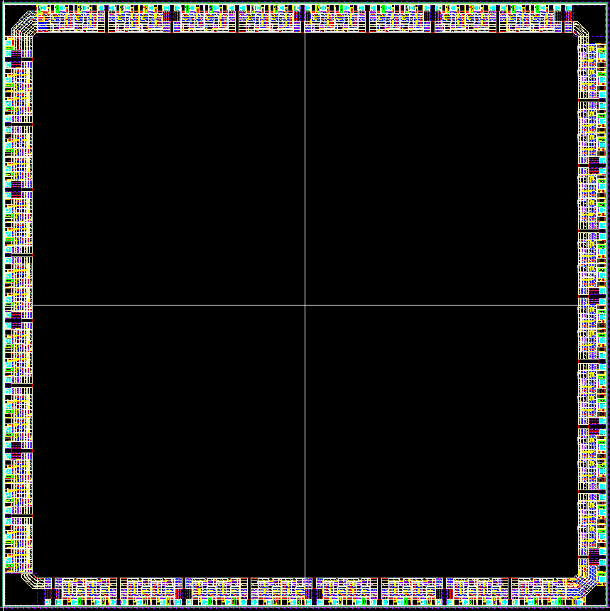
And a GDS file of the same:
Wow, that's a huge infodump right there. I had found the block diagram of the pins before, but that is much more detailed information than I had ever hoped for. It also comes at the perfect time as I'm also trying to wrap my head around some of the more complex Pin modes.
Thought you might like it.
I wish there was even more there, TBH. Many of the links were added a long time after the data was first posted on the forums. We certainly didn't didn't keep track of everything.
It might be possible to measure temperature using the ESD protection diodes. Has anyone done this? The P2 ADCs can measure beyond the rails, -0.825 to 4.125 volts according to my calculations. Not sure if this needs a proper constant current source or if a bias resistor will work. An easy way to test this would be to hook up a multimeter, positive to the pin, and negative to 3.3v. Use the diode check function.
Should be valid, in theory, but signal might be obscured a lot. Between the ADC's sore low frequency noisiness and the VIO lift from the pull-up, it'll probably be hard to see.
Heh, I wonder if the RevB Prop2 would have an advantage here. That can have twin ADCs sampling the same pin.
You could measure the body diodes, of an unused 'off' port MOSFETS, which you can do with a multimeter as the diode range injects a current. My meter says ~ 610mV
To self-measure would need a small injection current outside the rails, which could come from a battery + resistor.
Chip just pointed me to the Prop's IC packaging outfit - https://c44f5d406df450f4a66b-1b94a87d576253d9446df0a9ca62e142.ssl.cf2.rackcdn.com/2018/02/ePad_LQFP-TQFP_DS231.pdf
No indication of TjC thermal resistance to the exposed pad alone.
It gives that same TjA 20.6 figure. And it states it is for a PCB mount with heat spreading. But no added cooling solution. Although it does indicate an improved outcome with airflow, 15.3, so that could be a decent figure to work from if adding a heat sink.
Glad to see folks are trying out p2llvm!
The inline assembly does work (though some syntax is a bit different than what you'll see in spin or flex c), and I'm fully aware I haven't implemented all the instructions. there's a LOT of them and most are not needed when working with higher level code, but are definitely useful when working with inline assembly. I tend to just add them as I need them.
Reporting issues is great--that's probably the easiest way to get me to fix stuff (full disclosure I have a very busy schedule so I can't get to things quickly).
Regarding clock speeds, I run all my P2 boards (probably have >20 of them running at all times for my actual work projects, everything from 2 to 6 layer boards) at 300 MHz and never seen issues, including in high temp environments (approaching 100C ambient)
Hi @n_ermosh , it's been a while. Do you know if your LLVM works okay on MacOS with M2 chips? I've got a newer machine now and am interested to try your P2 LLVM again when I get a chance. Had problems running it on my older Mac with missing/incompatible include files etc so had to give up back then. Hopeful of a better result this time.
You've got some leeway there. The hubRAM instability line has 300 MHz crossing at 165 degC.
I figure an instability temperature slope equation of: Tji = (410 - Fclk) * 1.5
I haven't actually tested on M2, but I use it regularly on M1. I would be very surprised if it didn't work directly. I have an M2 mac at work I could try it on, but give it a shot and let me know if you run into weird issues.
Nice to see you here in the forum. I have already started to add the missing instructions and am slowly working through the list. I expect to be able to add around 90% of them without difficulties.
Wow, those are some impressive numbers and makes me feel a lot more confident about running the p2 with higher clocks. Did you do some specific things to the PCB layout or add active cooling to reach those speeds?
Wow so that was an embarrassing mistake. 100F, not C... but I do plan to do environmental testing to 85C. Nothing special on the layouts, just standard good practices (decoupling caps on all power pins, keep the clock close to the chip, short traces for everything etc). I also use a CMOS oscillator instead of a crystal as the 5MHz source.
Glad to see you are making progress on adding the instructions! There's also a test suite that needs to be eventually populated if we ever want this to be part of mainline LLVM, but that's only going to be possible if there are several maintainers that would support the backend continuously.
I guess I made my own mistake too. That Fclk in my equation is in MHz rather than Hz. Correction: Tji = (410 - Fclk / 1e6) * 1.5
Oh, that is only around 40C. But having a large number of boards running at 300 MHz is still a valuable information. I'm sure I can meet my requirements at 200 MHz, probably even 150 MHz. While I don't plan to run them above 40C ("human safe environment") I still prefer to have some headroom. Especially as I have no experience with designing an actual product.
I'm not sure if upstreaming the compiler to mainline LLVM is feasible. While it would be nice, I unfortunately have neither the time nor skill to help with maintaining it. However I'll look into the test suite and see what I can add there. As I'm only adding the instructions for usage in (inline) asm it should be relatively easy to add them.
Maybe I should take a look. I did a fair bit of work on flexspin, so maybe it's time to spread the love...