@Mickster said:
@aaaaaaaargh
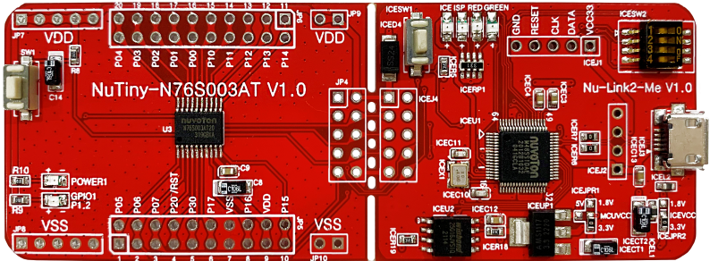
There's also the KISS module and it's a DIP.
I have a KISS board too, it’s nice but it has two rows of contacts on each side so not Dip, really. Try getting that onto a standard solderless breadboard…
I really like the Teensy or RP Pico 2 form factors so I vote for a P2 Flip ;-)
@VonSzarvas said:
About KISS board- I really like that too, and the pinout flexibility. With a 20mhz clock and maybe some more time for layout and power supply work it would be a nice plug and play package for prototyping.
Yes, it has the P2 headers, which seem to be the focus for Parallax, so it would be important to keep those.
There is also KISS2
@Mickster said:
I'd like a RP2350B or RP2354B (the ones with the most pins) + P2 + some other bits.
This would satisfy both the Python and MMBasic fans .
The Pi PICO is certainly worth thinking about, it did not even exist in early P2 days.
The main problem with the high pin count parts, is actually bringing all the pins out somewhere?
I did find this
End of 2024 will have available bare chips :
RP2350A QFN60 no flash $0.80
RP2350B QFN80 no flash $0.90
RP2354A QFN60 2Mbyte flash $1.00
RP2354B QFN80 2Mbyte flash $1.10
QFN60 types are 7 x 7mm and have 30 GPIOs, QFN80 types are 10 x 10mm and have 48 GPIOs.
Flash is added by stacking a QSPI die inside the package – and the prices above are for reels of 3,400.
Their PIO peripheral state engine is a great lead into P2 smart pins + COGS.
It has only 32 words per block, but you can do a lot in 32 words. A COG bumps that 64x
(they could have done even more with smarter opcodes... )
@VonSzarvas said:
Didn’t someone make a castellated format?
The P2Stamp is PLCC84 and a stunning example of shrink designing.
Other vendors have break-off designs, where a PropPlug+Debug+Field programmer (flash+button) are on a break/cut off panel.
P2D2 uses a small MCU as the UART, but in 2024 maybe a design could merge all of the above and use :
KISS(2) broad design and add a break-off RP2350 that is used for UART/PGM/Debug plus some parallel P2 pin connects
ie the RP2350 is used as an ungraded PropPlug
Would be wonderful if Parallax would take the SimpleP2 design and improve it.
If things like the USB, VGA connectors, mic, and the headers were left unpopulated, could maybe be at a lower cost than the Eval board. Also could leave barrel connector and QWIIC connector unpopulated...
It is sorta breadboard friendly because the one edge of the board could plug into breadboard...
Only 4 layers so maybe that saves a bit. Or, perhaps they could improve top speed going to 6 layers, like Eval...
One nice thing about this size board is that it's the same as old Parallax P1 boards, so can put on a BoeBot...
@Mickster said:
@aaaaaaaargh
There's also the KISS module and it's a DIP.
I have a KISS board too, it’s nice but it has two rows of contacts on each side so not Dip, really. Try getting that onto a standard solderless breadboard…
I really like the Teensy or RP Pico 2 form factors so I vote for a P2 Flip ;-)
Maybe you didn't get the memo
You have one set of headers below and one above (?)
Yes, like that. only with castellations, maybe added on the outside with the header holes too. I would need it to be an official Parallax product available through Digikey, etc. to get it stocked though...
I am moving, with all that that implies.. Else i might have time to take a run at it myself...
@Rayman said:
If things like the USB, VGA connectors, mic, and the headers were left unpopulated, could maybe be at a lower cost than the Eval board.
The Eval Board doesn't have any frills at all. It couldn't really get any cheaper in terms of minimalism. Why that doesn't translate to a cheap product? I guess there could be an argument for the number of expansion headers makes for lots of parts in total, even if they are individually cheap parts.
For the video applications, and I know that's not always the focus for all here, now we have HDMI audio functioning there's something to be said about making a small P2 board with uSD, PSRAM & HDMI consuming port B, and bring out all P2 port A pins along the two side edges. This would be breadboard friendly and give you 32 bits of IO to play with. Think of Cluso's board above with USB at one end and HDMI on the other (or VGA+AV as alternative board option), a switching reg dual output supply plus the uSD card for boot and maybe optional flash footprint people could solder to but in a wide DIP style format. The other approach is something like (and ideally mechanically compatible with) the Pi Zero format which isn't breadboard friendly directly but at least has a large group of vendors that can provide good expansion/prototyping options.
Update: If you go with the Pi Zero style format and include a USB port for P28-P31 which can be either host/client like the Pi you could get a nice standalone dev system out of it too. The powering USB port could have an FTDI chip for simple PropPlug compatible uploads or a direct USB client connection for the PC host (or somehow selectable if that's possible).
This may have been mentioned in the Forums previously, but with the demise of the Prop2 Eval Board,
would it be feasible for Parallax to consider releasing the Prop2 in the Raspberry Pi Zero form factor?

The board could have an HDMI port, micro SDHC card, 16MB SPI boot memory, PSRAM XMM memory, two USB ports,
and of course the 40 pin connector.

One USB port could serve as a power input and standard Console Port (on pins 62 & 63), while the other USB port
could run a USB driver currently being discussed by @Wuerfel_21, @rogloh, @macca, @SaucySoliton et al.
Given the size of the P2 itself, an exact replica of the Pi Zero format likely couldn't be done, but a close approximation might be possible. But the ability to stack an expansion/accessory board on top would be helpful.
Bottom line for me is that although the P2 Edge is a cool design, I really can't use it. I need a form factor that either has pins that can be breadboarded like Clusos design, or the KISS board, the P2 Stamp, a FLIP2, or something along the lines of a Pi Zero.
@VonSzarvas said:
...
I wonder if consolidating popular add-on boards into one or two variants of a more complete "ready-to-go" P2 carrier (similar size to the Propeller Activity Board) would be appropriate now; such boards should be useful for system-builders, developers and lean into education.
If you are looking at an Edge Carrier Board (plus) only, one simple way to check what to include, would be to check Parallax sales data on the existing small modules.
And probably be powered/programmed by USB-C, and have some QWIC/STEMMA/etc.. headers, rather than too many bulky P2 accessory headers?
Ideally a consolidated carrier should cost not much more than $30, to allow a bundle price point of ~$100 for the Edge + Board.
The RP2350 has a low price point, so it could also be considered as a smart USB-Bridge part.
It would allow faster burst speeds than mainstream USB Bridge parts, especially using the 520k SRAM as a crazy big buffer.
Current USB bridge examples (top down)
WCH CH347T TSSOP20 HS-USB + Crystal, 9Md speeds lcsc used to price this, strangely no longer showing prices ? Aliexpress suggests ~ US$1.30 small volumes
WCH CH343 new 6MBd model, FS-USB No Crystal This is an upgrade of the CH341 which was an upgrade of the CH340
CH343G SOP16N lcsc 65c/100+
CH343P QFN16_3x3 lcsc 75c/100+
Holtek HT42B534-2 3.4Mbps (48M/14) No Crystal SOP-16 43c/100 128 byte buffers and limited Baud speed.
Looking ahead a little
RP2350A QFN60 no flash $0.80/3400 RAM is 520KB 12MHz Xtal or OSC
RP2354A QFN60 2Mbyte flash $1.00/3400
Standard UART Baud rate on the PICOs seems to be a crude PCLK/16, so 9MBd would be 144MHz, 10Mbd would be 160MHz and 12MBd would be 196MHz
Using the PIO for UART should work faster.
The older RP2040 gives 133MHz PCLK, and web mention of 200MHz and 250MHz overclock seem common.
The newer RP2350 specs 150MHz and web mention of 300MHz overclock appears here https://dmitry.gr/?r=06. Thoughts&proj=11. RP2350
One combination here could be to have RP2354A firmware that supports USB-UART, and can sense a pin/button to dump top of flash to P2.
So far I have not found RP235x ROM boot times ? There are RP2040 comments that suggest 16-20ms ?
The P2 might fit in the gap between the miniHDMI port and microUSB port. I used a full size HDMI on this mockup.
Since there will be no camera connector, I put a USB type A connector there like a Pi-Zero would have with the Zero Stem add-on.
The Pi Zero needs dongles: A mini-HDMI adapter, and a microUSB to USB A female adapter to connect other devices.
I think the P2 Zero would be a hard sell. It would have inferior specs and would cost more. The P2 would be a good upgrade from the Pico, with more ADCs, DACs, and more IO pins.
One of the things I looked at when choosing what connectors was how many boards are available. There are over 1000 mikroBUS Click boards. Over 100 boards with QWIIC / Stemma QT interface. Of course many of us have an investment in P2 EVAL accessory boards so it would be good to have at least one of those connectors. I usually get at least one P2-ES Eval Protoboard when I place an order because those are consumable.
...one completely differently direction:
As P2 is especially interesting for motion control, a P2 board with 5 (?) sockets for 4988....DRV8825...TMC2209 step motor driver modules with DC voltage input up to 42V would be interesting, I think. I wonder, if a somewhat complete board for stepper control would act as some kind of "seed" for P2-based DIY routers, robots, milling machines, lathes, ....
These days I design my new attempt for a CNC knitting machine, which will have at least 4 axis with stepper motors. As there are plenty of difficult parts in this project, I try to use low cost but pretested elements.
I also would like to have some cycle control for a milling machine. For example to drill a precise pattern of deep bores in several depth steps without the need to go the long route with G-codes. Or a cycle to mill pockets.
@"R Baggett" said:
How about modules functionally equivalent to the edge in it's current variants with 4 sides castellated? It would probably fit in a little bigger than 2" X 2" with 100 mil spacing. easy to solder down on a perfboard for a one-off, and not terrible for use on a custom board. (Put it on the bottom and P2 for virtually zero footprint!)
I keep a dozen or so FLIPS in the cabinet at work.. turn 'em over in a couple of months or so. This would get at least that much play...
I'm liking this idea... If you take the edge and drop the dip switch, uSD, and leds, perhaps it could be small square with castellated sides. Maybe just two castellated sides? Or, maybe 4 is better for trace length.
I could go for that. But, pricewise, that would be the same as the Edge, I think...
Yes, I see a case for 2 sides for the breadboard angle.. if there were also holes for header, it would be possible to choose 2 sides and have a small-ish breadboard ability especially if the Vin and ground and programming pins were strategically placed and/or duplicated to make either orientation breadboard-able.
May also be possible to match trace length for all, or some subset of pins as well...
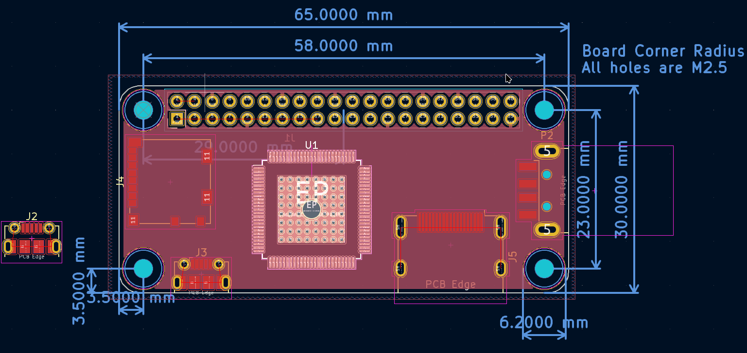
So something like this for starters. It would be 2.3" square with headers, 2.1" square castellated only. The circuitry would be mostly a shameless copy of the Edge, but it has a little more area than the Edge. It might have space for ft232 and a vertical usb C...__
Using the PIO for UART should work faster.
The older RP2040 gives 133MHz PCLK, and web mention of 200MHz and 250MHz overclock seem common.
The newer RP2350 specs 150MHz and web mention of 300MHz overclock appears here https://dmitry.gr/?r=06. Thoughts&proj=11. RP2350
One combination here could be to have RP2354A firmware that supports USB-UART, and can sense a pin/button to dump top of flash to P2.
So far I have not found RP235x ROM boot times ? There are RP2040 comments that suggest 16-20ms ?
Running 372MHz (378MHz if no HDMI). Anyone can purchase this directly from JLCPCB. For an order of 5, they work out at ~$25, fully populated.
PIO: Very cool. I am reading quadrature encoders, directly in the MMBasic interpreter @ sysclock/44 quadrature counts/sec.
A big RPi board has enough place to fit a P2 on it. There is a lot of "hats" available in this ecosystem. RPi compatible GPIO uses 28 pins. The rest of pins may be used for PSRAM (18), USB (2), digital video (8) and audio (2)
A big RPi board has enough place to fit a P2 on it. There is a lot of "hats" available in this ecosystem. RPi compatible GPIO uses 28 pins. The rest of pins may be used for PSRAM (18), USB (2), digital video (8) and audio (2)
@"R Baggett" said:
So something like this for starters. It would be 2.3" square with headers, 2.1" square castellated only. The circuitry would be mostly a shameless copy of the Edge, but it has a little more area than the Edge. It might have space for ft232 and a vertical usb C...__
Evanh, Eval headers would probably fit on top, might make uSD challenging.. Maybe take a page from Peter's book and face it over the P2. Maybe I can find a tall enough hinged one..
How did I miss the Prop2 Stamp? Where do I get one, or a few dozen? Much preferable for my use case, I went with the 100 mil header to keep the breadboard folks interested.. (And get rid of heat) figuring the widest application might, just might, end up in production...
Von Szarvas, Yeah it does look a lot like the EVAL. Totally accidental..
Is it too late for a P2 board that plugs into a 40-pin 0.6" DIP socket with 5V supply?
P0-P31 could go to 32 of the DIP pins, maybe with 5V to 3.3V translators. Some of the higher numbered pins could be used for onboard flash and HDMI & micro SD connectors at either end, with one or two headers perhaps for other functionality. It would need components on top and bottom and could be a tight fit, depending on how much is included.
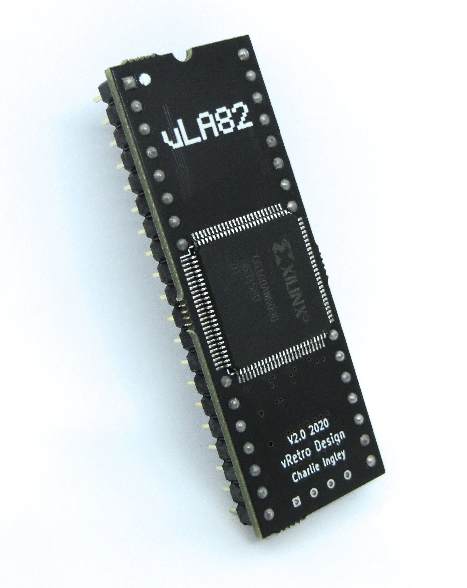
It could look similar to this:
The above is a replacement for the ZX Spectrum ULA and the Xilinx FPGA is the same package as the P2.
Good trick making the IC sit right on the DIP pins like that. I can only assume those few DIP pins are surface mounted underneath. Would need a very custom library part, or maybe done with three end-to-end DIP socket parts instead.


Comments
+1
Cluso’s design was (is?) the only breadboard friendly p2 board that can be soldered in after testing.
@aaaaaaaargh
There's also the KISS module and it's a DIP.
I have two of these and I prefer it to the Cluso design because there is no clutter.
Craig
I have a KISS board too, it’s nice but it has two rows of contacts on each side so not Dip, really. Try getting that onto a standard solderless breadboard…
I really like the Teensy or RP Pico 2 form factors so I vote for a P2 Flip ;-)
Yes, it has the P2 headers, which seem to be the focus for Parallax, so it would be important to keep those.
There is also KISS2
The Pi PICO is certainly worth thinking about, it did not even exist in early P2 days.
The main problem with the high pin count parts, is actually bringing all the pins out somewhere?
I did find this
End of 2024 will have available bare chips :
QFN60 types are 7 x 7mm and have 30 GPIOs, QFN80 types are 10 x 10mm and have 48 GPIOs.
Flash is added by stacking a QSPI die inside the package – and the prices above are for reels of 3,400.
Their PIO peripheral state engine is a great lead into P2 smart pins + COGS.
It has only 32 words per block, but you can do a lot in 32 words. A COG bumps that 64x
(they could have done even more with smarter opcodes... )
The P2Stamp is PLCC84 and a stunning example of shrink designing.
Other vendors have break-off designs, where a PropPlug+Debug+Field programmer (flash+button) are on a break/cut off panel.
P2D2 uses a small MCU as the UART, but in 2024 maybe a design could merge all of the above and use :
KISS(2) broad design and add a break-off RP2350 that is used for UART/PGM/Debug plus some parallel P2 pin connects
ie the RP2350 is used as an ungraded PropPlug
2 more mockups I made prior to the video board discussion
2 Mikrobus, 3 EVAL, QWIIC, USB-C,
This board is asymmetric so more pins are available when mounted vertically.
Pi Pico compatible with 1 EVAL connector
Would be wonderful if Parallax would take the SimpleP2 design and improve it.
If things like the USB, VGA connectors, mic, and the headers were left unpopulated, could maybe be at a lower cost than the Eval board. Also could leave barrel connector and QWIIC connector unpopulated...
It is sorta breadboard friendly because the one edge of the board could plug into breadboard...
Only 4 layers so maybe that saves a bit. Or, perhaps they could improve top speed going to 6 layers, like Eval...
One nice thing about this size board is that it's the same as old Parallax P1 boards, so can put on a BoeBot...
Maybe you didn't get the memo
You have one set of headers below and one above (?)
Craig
Yes, like that. only with castellations, maybe added on the outside with the header holes too. I would need it to be an official Parallax product available through Digikey, etc. to get it stocked though...
I am moving, with all that that implies.. Else i might have time to take a run at it myself...
The Eval Board doesn't have any frills at all. It couldn't really get any cheaper in terms of minimalism. Why that doesn't translate to a cheap product? I guess there could be an argument for the number of expansion headers makes for lots of parts in total, even if they are individually cheap parts.
For the video applications, and I know that's not always the focus for all here, now we have HDMI audio functioning there's something to be said about making a small P2 board with uSD, PSRAM & HDMI consuming port B, and bring out all P2 port A pins along the two side edges. This would be breadboard friendly and give you 32 bits of IO to play with. Think of Cluso's board above with USB at one end and HDMI on the other (or VGA+AV as alternative board option), a switching reg dual output supply plus the uSD card for boot and maybe optional flash footprint people could solder to but in a wide DIP style format. The other approach is something like (and ideally mechanically compatible with) the Pi Zero format which isn't breadboard friendly directly but at least has a large group of vendors that can provide good expansion/prototyping options.
Update: If you go with the Pi Zero style format and include a USB port for P28-P31 which can be either host/client like the Pi you could get a nice standalone dev system out of it too. The powering USB port could have an FTDI chip for simple PropPlug compatible uploads or a direct USB client connection for the PC host (or somehow selectable if that's possible).
We had a discussion about the Pi Zero form factor last year: https://forums.parallax.com/discussion/175346/raspberry-pi-zero-form-factor-for-p2-what
Given the size of the P2 itself, an exact replica of the Pi Zero format likely couldn't be done, but a close approximation might be possible. But the ability to stack an expansion/accessory board on top would be helpful.
Bottom line for me is that although the P2 Edge is a cool design, I really can't use it. I need a form factor that either has pins that can be breadboarded like Clusos design, or the KISS board, the P2 Stamp, a FLIP2, or something along the lines of a Pi Zero.
If you are looking at an Edge Carrier Board (plus) only, one simple way to check what to include, would be to check Parallax sales data on the existing small modules.
The RP2350 has a low price point, so it could also be considered as a smart USB-Bridge part.
It would allow faster burst speeds than mainstream USB Bridge parts, especially using the 520k SRAM as a crazy big buffer.
Current USB bridge examples (top down)
WCH CH347T TSSOP20 HS-USB + Crystal, 9Md speeds lcsc used to price this, strangely no longer showing prices ? Aliexpress suggests ~ US$1.30 small volumes
WCH CH343 new 6MBd model, FS-USB No Crystal This is an upgrade of the CH341 which was an upgrade of the CH340
CH343G SOP16N lcsc 65c/100+
CH343P QFN16_3x3 lcsc 75c/100+
Holtek HT42B534-2 3.4Mbps (48M/14) No Crystal SOP-16 43c/100 128 byte buffers and limited Baud speed.
Looking ahead a little
RP2350A QFN60 no flash $0.80/3400 RAM is 520KB 12MHz Xtal or OSC
RP2354A QFN60 2Mbyte flash $1.00/3400
Standard UART Baud rate on the PICOs seems to be a crude PCLK/16, so 9MBd would be 144MHz, 10Mbd would be 160MHz and 12MBd would be 196MHz
Using the PIO for UART should work faster.
The older RP2040 gives 133MHz PCLK, and web mention of 200MHz and 250MHz overclock seem common.
The newer RP2350 specs 150MHz and web mention of 300MHz overclock appears here
https://dmitry.gr/?r=06. Thoughts&proj=11. RP2350
One combination here could be to have RP2354A firmware that supports USB-UART, and can sense a pin/button to dump top of flash to P2.
So far I have not found RP235x ROM boot times ? There are RP2040 comments that suggest 16-20ms ?
The P2 might fit in the gap between the miniHDMI port and microUSB port. I used a full size HDMI on this mockup.
Since there will be no camera connector, I put a USB type A connector there like a Pi-Zero would have with the Zero Stem add-on.
The Pi Zero needs dongles: A mini-HDMI adapter, and a microUSB to USB A female adapter to connect other devices.
I think the P2 Zero would be a hard sell. It would have inferior specs and would cost more. The P2 would be a good upgrade from the Pico, with more ADCs, DACs, and more IO pins.
One of the things I looked at when choosing what connectors was how many boards are available. There are over 1000 mikroBUS Click boards. Over 100 boards with QWIIC / Stemma QT interface. Of course many of us have an investment in P2 EVAL accessory boards so it would be good to have at least one of those connectors. I usually get at least one P2-ES Eval Protoboard when I place an order because those are consumable.
...one completely differently direction:
As P2 is especially interesting for motion control, a P2 board with 5 (?) sockets for 4988....DRV8825...TMC2209 step motor driver modules with DC voltage input up to 42V would be interesting, I think. I wonder, if a somewhat complete board for stepper control would act as some kind of "seed" for P2-based DIY routers, robots, milling machines, lathes, ....
These days I design my new attempt for a CNC knitting machine, which will have at least 4 axis with stepper motors. As there are plenty of difficult parts in this project, I try to use low cost but pretested elements.
I also would like to have some cycle control for a milling machine. For example to drill a precise pattern of deep bores in several depth steps without the need to go the long route with G-codes. Or a cycle to mill pockets.
@"Christof Eb." CNC control does seem to be something P2 can do well and do other things at the same time…
Another board was just contemplating is one with P2 and friends on one side and a VGA touchscreen on the other...
Yes, I see a case for 2 sides for the breadboard angle.. if there were also holes for header, it would be possible to choose 2 sides and have a small-ish breadboard ability especially if the Vin and ground and programming pins were strategically placed and/or duplicated to make either orientation breadboard-able.
May also be possible to match trace length for all, or some subset of pins as well...
So something like this for starters. It would be 2.3" square with headers, 2.1" square castellated only. The circuitry would be mostly a shameless copy of the Edge, but it has a little more area than the Edge. It might have space for ft232 and a vertical usb C...__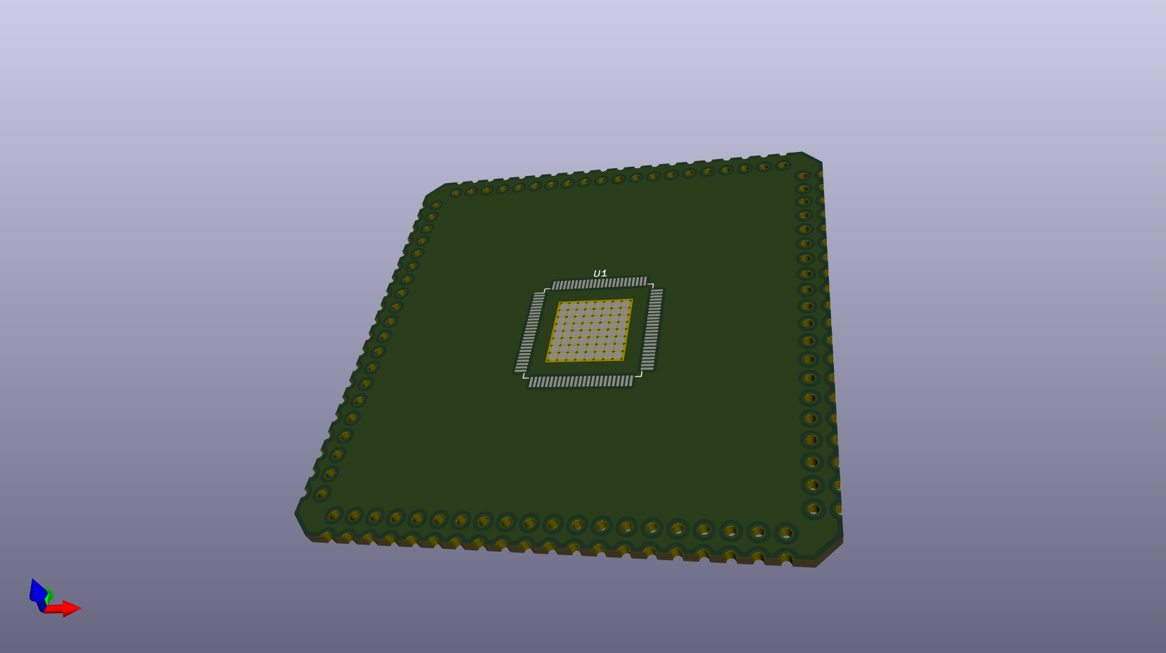
How about, along the same edges, breadboard headers underneath and Eval headers above?
Somehow reminds me of the P2 EVAL. Looks like an uber-condensed version!
Honey I Shrunk The Eval !
@jmg
Running 372MHz (378MHz if no HDMI). Anyone can purchase this directly from JLCPCB. For an order of 5, they work out at ~$25, fully populated.
PIO: Very cool. I am reading quadrature encoders, directly in the MMBasic interpreter @ sysclock/44 quadrature counts/sec.
I am considering a P2 add-on board for this
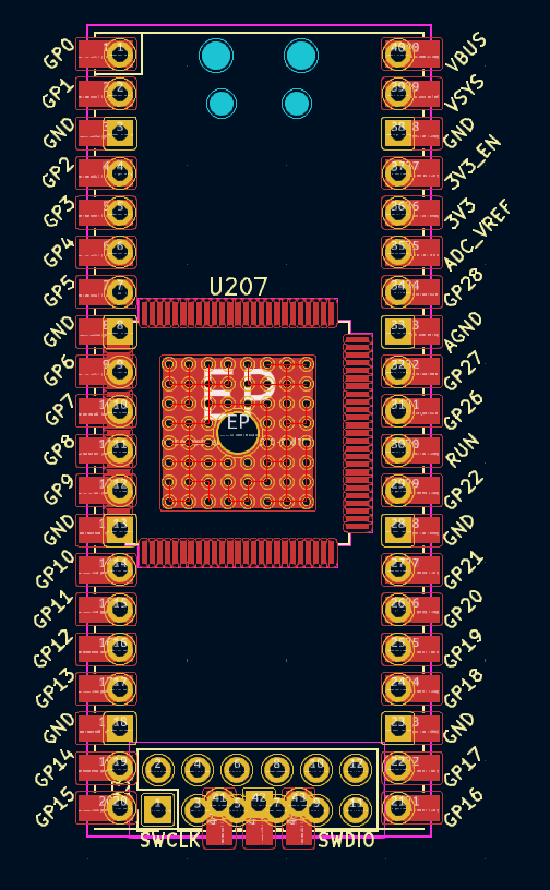
Noone mentioned a RPi form factor?
So let me mention it.
A big RPi board has enough place to fit a P2 on it. There is a lot of "hats" available in this ecosystem. RPi compatible GPIO uses 28 pins. The rest of pins may be used for PSRAM (18), USB (2), digital video (8) and audio (2)
It's been mentioned.
So as @Wuerfel_21 mentioned an p2 stamp: https://forums.parallax.com/uploads/editor/i4/hxlu7qcf8qz6.png
The pin pitch is double here. Baggett's drawing will be twice the dimensions of the Prop2 Stamp.
Evanh, Eval headers would probably fit on top, might make uSD challenging.. Maybe take a page from Peter's book and face it over the P2. Maybe I can find a tall enough hinged one..
How did I miss the Prop2 Stamp? Where do I get one, or a few dozen? Much preferable for my use case, I went with the 100 mil header to keep the breadboard folks interested.. (And get rid of heat) figuring the widest application might, just might, end up in production...
Von Szarvas, Yeah it does look a lot like the EVAL. Totally accidental..
Three sides with Eval headers would be heaps.
Is it too late for a P2 board that plugs into a 40-pin 0.6" DIP socket with 5V supply?
P0-P31 could go to 32 of the DIP pins, maybe with 5V to 3.3V translators. Some of the higher numbered pins could be used for onboard flash and HDMI & micro SD connectors at either end, with one or two headers perhaps for other functionality. It would need components on top and bottom and could be a tight fit, depending on how much is included.
It could look similar to this:
The above is a replacement for the ZX Spectrum ULA and the Xilinx FPGA is the same package as the P2.
Good trick making the IC sit right on the DIP pins like that. I can only assume those few DIP pins are surface mounted underneath. Would need a very custom library part, or maybe done with three end-to-end DIP socket parts instead.
How do they connect the middle DIP pins ?