This all makes sense now. The high side mosfet driver runs between 20 and 40 volts. Never goes to zero! So the high side of the logic level input mosfets were always ON.
On the high side of this BLDC motor driver you can have the mosfets all touch the heat sink. On the low side they must be insulated. I’m using mica and silicone But in making these heat sinks it occurred to me that these may make for some degree of shielding of noise leaking the mosfets if I tied both heat sinks to GND. Which means insulating the high side as well. I’ve never had issues that I’m aware of with noise on these boards affecting the P1 board 8-10” away. But it costs nothing to tie them to GND. Just a little wire.
If you use thick anodized aluminum and use a nylon screw you won't need to use mica.
Also... I didn't think so until I did a side-by-side test myself ... black anodized aluminum will dissipate heat better than white anodized aluminum or bare metal aluminum.
Nice! ... Ever thought of incorporating a heat pipe?
Thanks I won’t send this out to anodize, McMaster sells black anodized but not sure they do 1/8”, I’ll check. No idea what a heat pipe is. But this is probably the end result for me it is 500x the mass I had before so hopefully will help.
@"T Chap" said:
On the high side of this BLDC motor driver you can have the mosfets all touch the heat sink. On the low side they must be insulated. I’m using mica and silicone But in making these heat sinks it occurred to me that these may make for some degree of shielding of noise leaking the mosfets if I tied both heat sinks to GND. Which means insulating the high side as well. I’ve never had issues that I’m aware of with noise on these boards affecting the P1 board 8-10” away. But it costs nothing to tie them to GND. Just a little wire.
Thoughts?
I would start to worry about larger heatsinks putting stress on the leads and plating.
When doing power designs, we always screwed the heatsink to the board and then attached power devices, usually with clips.
We used standard al extrusions, U or square with slots cut in them, then anodised. For multiple parts we clipped to both sides of 25mm square.
That is very low stress and thermally cycling tolerant.
In 2023, I would focus first on 'better mosfets' - the IRF540 is a 'mature' part with 70mOhms, whilst something like lcsc's PTF10HN08 specs 8.2mOhms, in an easy to apply TO220F package. (100+ US$0.2317)
Addit:
With modest shuffling, you may be able to fit a pre-done heatsink like this ?
Thanks jmg. I am now using <10Rds TO220 As for sinks. I don’t have the space to fit those and can’t change the board size. These are not that heavy and very simple to add supports glued to the PCB. I had zero heat sink before so what I have is quite an improvement. further I am adding temp sensors to each aluminum plate and will monitor the temp and shut down if exceeding the average temperature. I can’t do that with 6 separate pieces. Granted one sensor in the center of mass is not perfect but better than nothing. I think this will solve my issues.
@"T Chap" said:
... But in making these heat sinks it occurred to me that these may make for some degree of shielding of noise leaking the mosfets if I tied both heat sinks to GND. Which means insulating the high side as well. I’ve never had issues that I’m aware of with noise on these boards affecting the P1 board 8-10” away. But it costs nothing to tie them to GND. Just a little wire. >
Don't bother. As far noise is concerned, the + supply is pretty much the same as ground so long as the supply has good filtering. If anything, just tie a good capacitor from the + side heat sink over to the ground plane.
The heat sink is very pretty. I wonder though how much the castellations add to the benefit. In any case, maybe make the bottom edge straight across in order to maximize contact area and heat transfer from the transistor to the sink.
I just thought of that as fins. Easy to add or not add. Seemed like at the time it was more surface area for air contact. Probably not though. But I will check the bottom for maximum contact surface
@"T Chap" said:
I just thought of that as fins. Easy to add or not add. Seemed like at the time it was more surface area for air contact. Probably not though. But I will check the bottom for maximum contact surface
That level of detail will only matter if you have forced air cooling.
Otherwise, the simpler larger Al area will have more thermal inertia, and cost less because you taking time and are removing material.
Nice piece of extrusion! I can’t fit it with all my connectors and caps but I can make a rectangular aluminum with no cool looking fins though. Thanks for the suggestions


Comments
This all makes sense now. The high side mosfet driver runs between 20 and 40 volts. Never goes to zero! So the high side of the logic level input mosfets were always ON.
Thanks for the help!
This is an acrylic mock-up of the aluminum heat sink idea.
You can easily switvh more than 40 Amps without any heatsint other than a small area on circuit board.
On the high side of this BLDC motor driver you can have the mosfets all touch the heat sink. On the low side they must be insulated. I’m using mica and silicone But in making these heat sinks it occurred to me that these may make for some degree of shielding of noise leaking the mosfets if I tied both heat sinks to GND. Which means insulating the high side as well. I’ve never had issues that I’m aware of with noise on these boards affecting the P1 board 8-10” away. But it costs nothing to tie them to GND. Just a little wire.
Thoughts?
If you use thick anodized aluminum and use a nylon screw you won't need to use mica.
Also... I didn't think so until I did a side-by-side test myself ... black anodized aluminum will dissipate heat better than white anodized aluminum or bare metal aluminum.
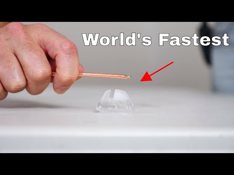
Nice! ... Ever thought of incorporating a heat pipe?
Thanks I won’t send this out to anodize, McMaster sells black anodized but not sure they do 1/8”, I’ll check. No idea what a heat pipe is. But this is probably the end result for me it is 500x the mass I had before so hopefully will help.
Heat Pipe demonstration video:
I would start to worry about larger heatsinks putting stress on the leads and plating.
When doing power designs, we always screwed the heatsink to the board and then attached power devices, usually with clips.
We used standard al extrusions, U or square with slots cut in them, then anodised. For multiple parts we clipped to both sides of 25mm square.
That is very low stress and thermally cycling tolerant.
In 2023, I would focus first on 'better mosfets' - the IRF540 is a 'mature' part with 70mOhms, whilst something like lcsc's PTF10HN08 specs 8.2mOhms, in an easy to apply TO220F package. (100+ US$0.2317)
Addit:
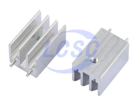
With modest shuffling, you may be able to fit a pre-done heatsink like this ?
https://www.lcsc.com/product-detail/Heat-sink-span-style-background-color-ff0-heatsink-span_XSD-XSD309-067_C286228.html
double pins for good torsion and good pin placement for low leverage. 11+ US$0.1361
Thanks jmg. I am now using <10Rds TO220 As for sinks. I don’t have the space to fit those and can’t change the board size. These are not that heavy and very simple to add supports glued to the PCB. I had zero heat sink before so what I have is quite an improvement. further I am adding temp sensors to each aluminum plate and will monitor the temp and shut down if exceeding the average temperature. I can’t do that with 6 separate pieces. Granted one sensor in the center of mass is not perfect but better than nothing. I think this will solve my issues.
Don't bother. As far noise is concerned, the + supply is pretty much the same as ground so long as the supply has good filtering. If anything, just tie a good capacitor from the + side heat sink over to the ground plane.
The heat sink is very pretty. I wonder though how much the castellations add to the benefit. In any case, maybe make the bottom edge straight across in order to maximize contact area and heat transfer from the transistor to the sink.
I just thought of that as fins. Easy to add or not add. Seemed like at the time it was more surface area for air contact. Probably not though. But I will check the bottom for maximum contact surface
That level of detail will only matter if you have forced air cooling.
Otherwise, the simpler larger Al area will have more thermal inertia, and cost less because you taking time and are removing material.
If your board is over 60.5mm, this one may fit ? (60.5 x 11 x 20) - needs two holes added.
https://www.lcsc.com/product-detail/Heat-sink-heatsink_XSD-60x11x20_C4689.html
Nice piece of extrusion! I can’t fit it with all my connectors and caps but I can make a rectangular aluminum with no cool looking fins though. Thanks for the suggestions