

Smart Pin PWM mode output state monitoring
 Phonos
Posts: 45
Phonos
Posts: 45
Is there a way to read in real time the smart pin output state when it is in PWM mode? As I understand things the OUTx register is over-ridden so can not be used to actually see the pin state. Or, do I have to count clock cycles after starting the pin to 'manually' determine the pin state?
Comments
WRPIN pin configuration instruction can be used to redirect inputs of a specific pin number. Then, something like TESTP reads from a different physical pin to the pin number specified in TESTP.
Once configured it stays that way until another WRPIN of that pin, or a chip reset is performed.
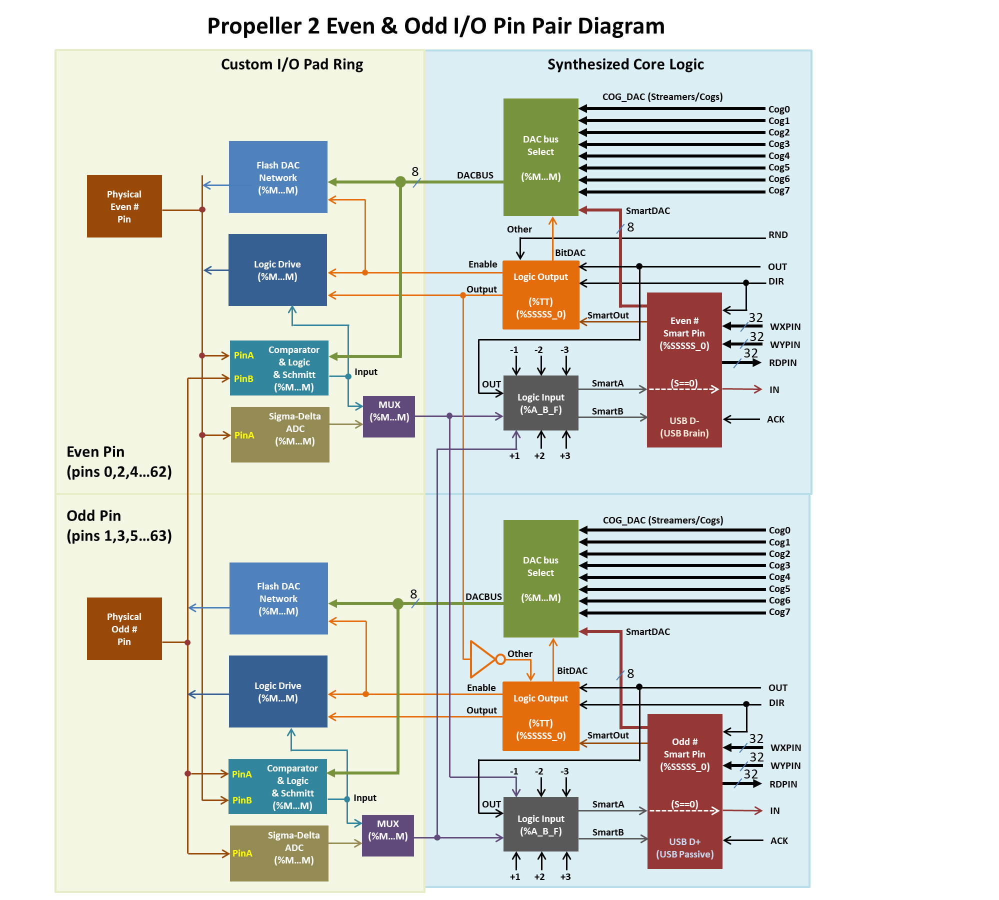
EDIT: This diagram might help. The part of interest is the "Logic Input" block. It has eight inputs with six of them coming from other physical pins.
Something like this...
CON
_clkfreq = 297_000_000 'Standard clock frequency = 160 MHz
PWM_PINS = 0 addpins 2
PWM_CONFIG = P_PWM_TRIANGLE | P_OE
PWM_DIV = 1
PWM_FRAME = 2000
PWM_DUTY = 200
SENSE_PINS = 3 addpins 2
SENSE_CONFIG = P_MINUS3_A | P_OE
SENSE_MASK = %111 << 3
DAT
org
fltl o_pins
wrpin o_conf, o_pins
wxpin o_xpar, o_pins
wypin o_ypar, o_pins
dirh o_pins
    fltl  i_pins
    wrpin i_conf, i_pins
    dirh  i_pins
.loop mov state, outa
and state, i_mask wz
if_nz jmp #.loop
o_pins long PWM_PINS
o_conf long PWM_CONFIG
o_xpar long PWM_DIV + (PWM_FRAME << 16)
o_ypar long PWM_DUTY
i_pins long SENSE_PINS
i_conf long SENSE_CONFIG
i_mask long SENSE_MASK
state res 1
Sorry about the poor formatting. How do I paste code from Propeller Tool?
Use three back-ticks (on tilde key on US keyboard) above and below your code.
CON _clkfreq = 297_000_000 'Standard clock frequency = 160 MHz PWM_PINS = 0 addpins 2 PWM_CONFIG = P_PWM_TRIANGLE | P_OE PWM_DIV = 1 PWM_FRAME = 2000 PWM_DUTY = 200 SENSE_PINS = 3 addpins 2 SENSE_CONFIG = P_MINUS3_A | P_OE SENSE_MASK = %111 << 3 DAT org fltl o_pins wrpin o_conf, o_pins wxpin o_xpar, o_pins wypin o_ypar, o_pins dirh o_pins fltl i_pins wrpin i_conf, i_pins dirh i_pins .loop mov state, outa and state, i_mask wz if_nz jmp #.loop o_pins long PWM_PINS o_conf long PWM_CONFIG o_xpar long PWM_DIV + (PWM_FRAME << 16) o_ypar long PWM_DUTY i_pins long SENSE_PINS i_conf long SENSE_CONFIG i_mask long SENSE_MASK state res 1Much better.
Here is my problem. I want to measure current on load only when switch is on (not average).
There is a specific smartpin mode for this. It modulates its own PWM based on live feedback. It can be setup to use an internal voltage comparator even. A similar question I answered - https://forums.parallax.com/discussion/comment/1552380#Comment_1552380
I will take a look at the SMPS features. One of the limitations to my original post is the adjacent pin input has to be within +/-3 pins. The driver board I am using groups all of the switch inputs (8 total) so it is not possible to designate the adjacent pin. I need to use another strategy to measure current at the appropriate intervals. Perhaps I could build an interface board that conveniently introduces adjacent pins.
It appears that the SMPS does have the dual control capability for V and I inputs but, they are intended to operate on the 'smoothed' output of the power supply . The circuit shown above will produce a load current that is pulsed at the input PWM frequency. To get the actual 'ON' current I want to measure only at the duty cycle of the PWM. So, I am back to using an adjacent pin strategy to detect pulses on as many fet pins as I can get adjacent to.
Thank you very much for your help here.
Could you read the average and then use the PWM on time, which you know, to calculate back to the PWM on equivalent current ?
I believe the current (I) input (smartB) is designed for per-pulse modulation. Certainly that is the input that mattered for me to manage the clocking cut-off when I made the self terminating clock gen. Pulse output stopped, part way through the pulse, as long as smartB was held. And as soon as smartB input released it could resume pulses.
The only response lag was that of the internal I/O staging that all the pins have. About 4 sysclock ticks for a smartpin.
Or select the code and then "Code" from the drop-down menu.
Why not just connect the PWM output to another pin with a wire? So you are not limited to adjacent pins.
But you don't really need another pin to detect the start of the high pulse. If you read the IN of the PWM smartpin, you get a high every time the PWM cycle starts. Now you only need to start the PWM cycle with a High instead of a Low, this is possible with setting the P_INVERT_OUTPUT bit in the pin config. You also need PWM_SAWTOOTH instead of TRIANGLE. For sure the Pulswidth setting is then invers (high values = short pulses, low values = long pulses).
Andy
@Andy
That is the sort of solution I was hoping for, but...
fails to pulse the LED (should be a 500msec period with 50% duty). Am I not reading the smart pin IN correctly?
Realizing that IN is only high for the first clock of the frame I tried to capture that event...
 xpar.word[0] := $FFFF
 xpar.word[1] := 1000
 ypar := 0 #> 500 <# xpar.word[1] - 1
 pinstart(PWM1, P_PWM_SAWTOOTH | P_INVERT_OUTPUT | P_OE, xpar, ypar)

         org
.loop    testp  #PWM1  wc
if_nc    jmp    #.loop
         drvnot #LED1
         waitx  ct1
         jmp .loop

ct1  long  _CLK / 8

end
but this doen't work either.
But this works!
xpar.word[0] := $FFFF xpar.word[1] := 1000 ypar := 0 #> 500 <# xpar.word[1] - 1 pinstart(PWM1, P_PWM_SAWTOOTH | P_INVERT_OUTPUT | P_OE, xpar, ypar) org .loop and INA, mask wz if_z jmp #.loop drvnot #LED1 waitx ct1 jmp #.loop ct1 long _CLK / 8 mask long 1 << PWM1 endThe IN goes high until you clear it with AKPIN, so this should work:
 xpar.word[0] := $FFFF
 xpar.word[1] := 1000
 ypar := 0 #> 500 <# xpar.word[1] - 1
 pinstart(PWM1, P_PWM_SAWTOOTH | P_INVERT_OUTPUT | P_OE, xpar, ypar)

         org
.loop    testp  #PWM1  wc
  if_nc  jmp    #.loop
         akpin  #PWM1
         drvnot #LED1
         jmp #.loop
end
You can also detect the pos edge of IN with an event:
 xpar.word[0] := $FFFF
 xpar.word[1] := 1000
 ypar := 0 #> 500 <# xpar.word[1] - 1
 pinstart(PWM1, P_PWM_SAWTOOTH | P_INVERT_OUTPUT | P_OE, xpar, ypar)

         org
         setse1 #%001<<6 + PWM1      'pos edge event on PWM1 pin
.loop    waitse1
         akpin  #PWM1
         drvnot #LED1
         jmp #.loop
end
Andy
That is the exact answer. Detect the IN event and jump with an interrupt, then begin logging ammeter values.
Thanks again for great help.
Now there is another question about timing. Say the ADC time per sample is T = 2^^(ENOB-1) / CLKFREQ. Acquisition needs to fit in the high time window W = (DIV / CLKFREQ) * FRAME * (DUTY / FRAME) . Then the number of samples should be N = W / T . This works out to be N = DIV *DUTY / (2^^(ENOB-1))
Does this seem reasonable (?) :
xpar.word[0] := $FFFF xpar.word[1] := 1000 ypar := 0 #> 500 <# xpar.word[1] - 1 pinstart(PWM1, P_PWM_SAWTOOTH | P_INVERT_OUTPUT | P_OE, xpar, ypar) enob := 9 pinstart(ANIN1, P_ADC | P_ADC_1X, (enob - 1), 0) div := $FFFF frame := 1000 duty := 500 n_sample := div * duty / (1<< (enob - 1)) org setse1 #%001<<6 + PWM1 'pos edge event on PWM1 pin setse2 #%001<<6 + ANIN1 'pos edge event on ANIN1 pin .loop waitse1 akpin #PWM1 rep #4, n_sample waitse2 akpin #ANIN1 rdpin amp_val, #ANIN1 add sum, amp_val qdiv sum_val, n_sample mov sum_val, #0 getqx amp_val jmp #.loop endedit
Hey Phonos
I have just noticed that the PMW cycle already starts with a high puls, so you don't need the P_INVERT_OUTPUT. Makes it a bit simpler to set the pulsewidth.
What Load do you control with the PWM? For a resistive load I think to measure one sample at the right time is good enough, for inductive loads the average current over the whole cycle may be needed.
If you need the peak current, you can measure continuously and detect the maximal value.
Andy
Hi Andy.
I noticed that in the documentation and verified with a test...
 xpar.word[0] := $FFFF
 xpar.word[1] := 1000
 ypar := 500
 pinstart(PWM1, P_PWM_SAWTOOTH | P_INVERT_OUTPUT | P_OE, xpar, ypar)

 org
           mov     ijmp1, #.isr
           setse1  #%001<<6 + PWM1      'pos edge event on PWM1 pin
           setint1 #event_se1
           dirl    #TP1
           drvh    #LED1

  .loop    nop
           jmp     #.loop

  .isr     akpin   #PWM1
           waitx   #8
           testp   #TP1          wc
  if_c     drvl    #LED1

           reti1
end
The load is a BLDC motor, trying to measure back emf and total current during the appropriate switch sequences. So, I probably would like to log the entire ADC cycle(s).
As an aside, when I measure the PWM output with an ADC configured pin, the measurement only reads 1.7 volts on the logic-1 state. Is this an error in my code?
Turns out a 1.5K pull down solves the dilemma.
Phonos,
It sounds like your signal is unipolar - needing a pull-down to provide a lower impedance signal.
The ADC inputs use virtual ground at VIO/2 voltage (about 1.7 volts) with 540 kR (x1 gain) inline resistor. So, they will pull to that voltage if the signal is not relatively low impedance.
For my testing I had P0 (smart pin PWM) directly wired to P1 (smart pin ADC_1X). Are there schematics which elaborate this behavior? I do not understand what is going on here.
If I configure the PWM as a DAC smart pin it seems to read just fine. What is the difference?
Inputs are functional at all times - no matter what the outputs are doing. If a DAC is driving a pin to 75% then the logic level input on the same pin sees that as a high.
The exception is ADC mode. It is only engaged in a few configs. And rightly so since it loads the pin toward VIO/2. Low-level pin modes table - https://forums.parallax.com/discussion/comment/1497769/#Comment_1497769
At the end of the Spin2 Language Google Doc there is a long list of predefined mode names. It shows the relevant bit patterns which match what's in the linked table. The linked table shows which ones can be combined.
Further reading - https://forums.parallax.com/discussion/comment/1494131/#Comment_1494131
and - https://forums.parallax.com/discussion/comment/1524494/#Comment_1524494
and - https://forums.parallax.com/discussion/comment/1484327/#Comment_1484327
and - https://forums.parallax.com/discussion/comment/1510730/#Comment_1510730
Mode setting gets more complicated when engaging a smartpin as well. The smartpin uses DIR for its reset/enable control and it uses IN for its ready indicator. Therefore, when using the smartpin then DIR and IN no longer function in their normal pin controls.
With the smartpin engaged, the pin's DIR can be toggled using one bit of the mode word:
P_OEThe pin's input is absorbed by the smartpin so is not directly readable unless another nearby pin is redirected.Can you provide some more information about what you actually intend to do and possibly post a schematic? Is the load an inductive one (motor, solenoid or something similar)? What PWM frequency are you using and what precision do you expect from the current measurement?
I do something similar when driving motors with an IGBT or MOSFET power stage. There are basically two methods for measuring the current through the load depending on budget and required accuracy.
@ManAtWork
Sorry about the long response delay. I have been working on getting code working, with a lot of help from the forum!
This application is for the Parallax motor driver board. I have a working program that drives the fets from the hall commutation sequence and reads both motor current and back emf at the correct time in the sequence. In addition, the independent duty cycle for each is driven by joystick reading from a gamepad controller. The Propeller2 works as slave to a Raspberrypi4 that uses a simple UI written in Python to send gamepad values over ttyS0 to a smartpin serial interface, while getting motor status over ttyUSB0. The Python code also does an autoload of the Spin2 program which gets compiled remotely and sent to the pi4 using scp from a windows PC. I would love to use the rpi4 to do the compilation but have been having a hard time finding an IDE that runs on the pi.