@DigitalBob said:
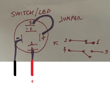
Your drawing of the JonnyMac circuit is wrong. Switch LED+, with resistor goes to your 5V, the R1,100 ohm goes to switch pin 3. Not the BS2.
I like your suggestion is less work. I have 700 seats! I was hoping to be able to use what is already in place. With your circuit I will have to open all seats to add an extra cable and solder the resistor.
I guess I have no other choice uh?
@DigitalBob said:
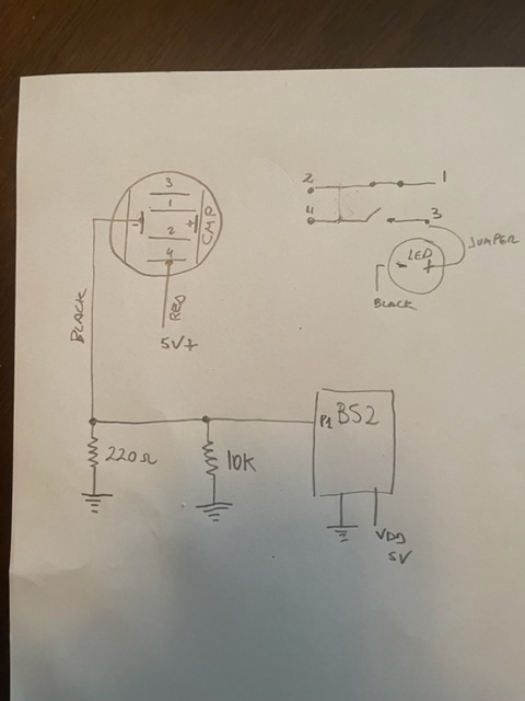
This is my schematic. JM listed a circuit to drive the LED on the switch.
I see by your button photos that the switch is wired to press the button and it lights the Led. To make it easier I would Leave it like that and use it as a current loop. The black feed wire with the red and black is that very long and runs down your rows to a central location? Earlier you showed a step down circuit, is that how everything is wired now?. If so I might have solution without re-inventing the wheel.
Get rid of your step down volt divider. Put a 100 ohm and 120 ohm resistor in series. The 100 ohm resistor connects to your 5V and the other end with 120 resistor connects to your red wire out to your switch and the black wire to ground. Now the junction point where the 100 ohm and 120 ohm resistor connect together is your trigger voltage point for your BS2 pin.. the junction point voltage will be 5V without the button pressed and about 2.27 volts with led sucking 20 Ma. Will be a little higher I didn’t factor the 20 ma. Led
Correct the wire goes down the seat to a center location. The step down was my initial idea. I don’t know how the system that is in place works. It just go to a black box in the middle of the row. I want to use the same wiring. If possible
@DigitalBob said:
I see by your button photos that the switch is wired to press the button and it lights the Led. To make it easier I would Leave it like that and use it as a current loop. The black feed wire with the red and black is that very long and runs down your rows to a central location? Earlier you showed a step down circuit, is that how everything is wired now?. If so I might have solution without re-inventing the wheel.
I will try later today and let you know. You know how much appreciate your help? Thanks a lot Bob!
@DigitalBob said:
Get rid of your step down volt divider. Put a 100 ohm and 120 ohm resistor in series. The 100 ohm resistor connects to your 5V and the other end with 120 resistor connects to your red wire out to your switch and the black wire to ground. Now the junction point where the 100 ohm and 120 ohm resistor connect together is your trigger voltage point for your BS2 pin.. the junction point voltage will be 5V without the button pressed and about 2.27 volts with led sucking 20 Ma. Will be a little higher I didn’t factor the 20 ma. Led
Luis, this schematic should solve your problem without rewiring and re-inventing the wheel. 2.0 volts should be good enough to send the BS2 into a low state. This is based on about a 20 ma Led.
Really??? I will try later tonight. If want my number send me a message and I’ll keep you post of this amazing project! Thanks
@DigitalBob said:
Luis, this schematic should solve your problem without rewiring and re-inventing the wheel. 2.0 volts should be good enough to send the BS2 into a low state. This is based on about a 20 ma Led.
Finally! Yes works that way! Nice an bright LED light (see picture). I want to mention 2 and 4 are no connected together as the previous circuit posted. But I'm not using pin 2 so everything is good. I know @JonnyMac is going to be worry about damaging the BS2 pins with this circuit. What are your thoughts? Also when I hook up the 13 buttons (seats) how many amperes do I need on the 5V power supply that is also powering the Xbee (SIP adapter) and the BS2?
Thanks a lot again!
@DigitalBob said:
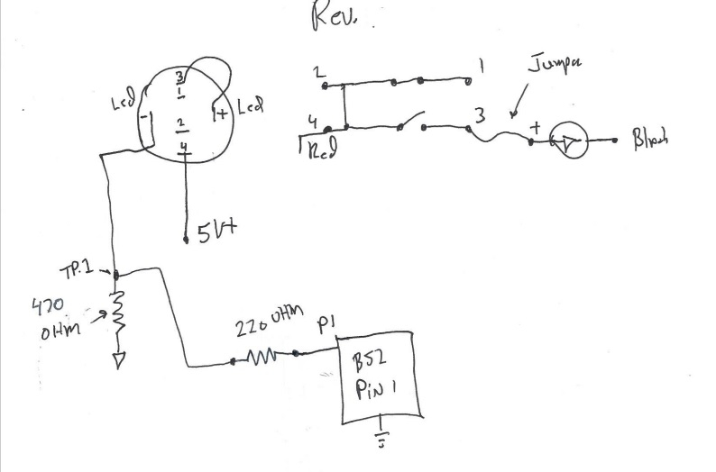
Had to revise the schematic, the 220 ohm resistor is on "-" Neg. side of the Led. Tested it and works.
Yeah, I almost forgot you can eliminate the 10K resistor and put a 100 or 220 ohm in series on the line that goes into the Bs2 pin. I'm driving the Led to 15-20 Ma. you could use a 470 ohm to drop the current to 10 Ma., maybe slightly dimmer. Anyway this was a simple low cost solution. When the button is open the 220 Ohm pulls the pin low to 0 volt, when the button is on with the Led lit, the pin should be at 3.3 volt. I think the Bs2 threshold from low to high is around 1.4 Volt. So total amps., if each led draws 15-20 Ma. that's 20 Ma X 13 = 260 Ma. max. about 1/4 amp.
Do you mind to make a final drawing with the correct values? Please!
@DigitalBob said:
Yeah, I almost forgot you can eliminate the 10K resistor and put a 100 or 220 ohm in series on the line that goes into the Bs2 pin. I'm driving the Led to 15-20 Ma. you could use a 470 ohm to drop the current to 10 Ma., maybe slightly dimmer. Anyway this was a simple low cost solution. When the button is open the 220 Ohm pulls the pin low to 0 volt, when the button is on with the Led lit, the pin should be at 3.3 volt. I think the Bs2 threshold from low to high is around 1.4 Volt. So total amps., if each led draws 15-20 Ma. that's 20 Ma X 13 = 260 Ma. max. about 1/4 amp.
I know @JonnyMac is going to be worry about damaging the BS2 pins
Actually, I don't care -- it's your project, not mine. And I never said you'd damage pins; I said the pin limits the amount of current it can sink or source. By using an external buffer, that becomes a non-issue.
You do realize, right, that this is turning your 10K pull-down into a 215-ohm pull-down?
Oh I see. I will replace with a 470 ohm to drop the current to 10 Ma. as @DigitalBob suggested. JonnyMac you help me always with my projects! I really appreciate what you do for us to learn!!!! You are so talented my friend!!!
Thanks a lot!!! God bless you !!!
@JonnyMac said:
I know @JonnyMac is going to be worry about damaging the BS2 pins
Actually, I don't care -- it's your project, not mine. And I never said you'd damage pins; I said the pin limits the amount of current it can sink or source. By using an external buffer, that becomes a non-issue.
You do realize, right, that this is turning your 10K pull-down into a 215-ohm pull-down?
IMO, you should wire the circuit like this if you only want the LED to light when the button is pressed. This puts the LED circuit and the input circuit in parallel and not in conflict with each other. The 220 is for safety and could be removed -- just don't make that pin you connect to an output-low.
When the button is pressed you will draw 0.5mA plus your LED current.
You need to ensure that the voltage at TP1 when the button is pressed is above the BS2 VIH level (since you're now using the LED and the resistor as a voltage divider).
My latest ciruit is good to go. The TP.1 voltage is 3.3V, not 5V+ but plenty. The TTL voltage threshold is 1.4 Volts from low to high and high to low is 0.8V. Its your call just keeping it simple and low cost.
@DigitalBob said:
My latest ciruit is good to go. The TP.1 voltage is 3.3V, not 5V+ but plenty. The TTL voltage threshold is 1.4 Volts from low to high and high to low is 0.8V. Its your call just keeping it simple and low cost.


Comments
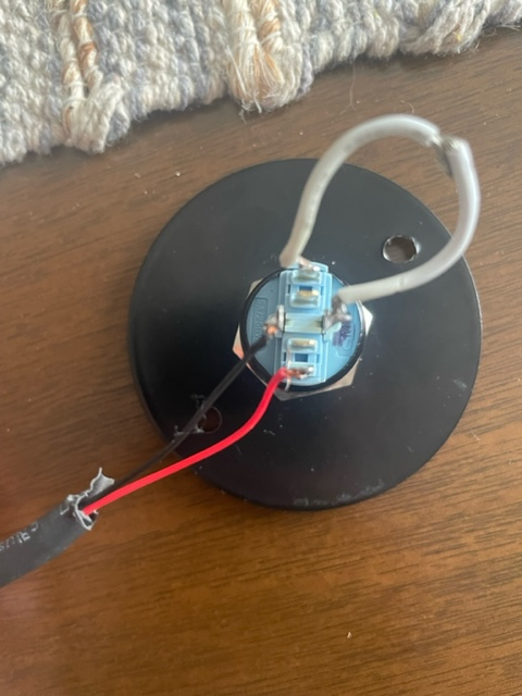
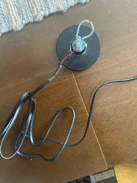
Can you post or refer to the drawing of the switch wiring as it stands now in your theater.
Do you mind to draw it? Im confused now…
tes. see pictures please
This is my schematic. JM listed a circuit to drive the LED on the switch.
I like your suggestion is less work. I have 700 seats! I was hoping to be able to use what is already in place. With your circuit I will have to open all seats to add an extra cable and solder the resistor.
I guess I have no other choice uh?
I see by your button photos that the switch is wired to press the button and it lights the Led. To make it easier I would Leave it like that and use it as a current loop. The black feed wire with the red and black is that very long and runs down your rows to a central location? Earlier you showed a step down circuit, is that how everything is wired now?. If so I might have solution without re-inventing the wheel.
Get rid of your step down volt divider. Put a 100 ohm and 120 ohm resistor in series. The 100 ohm resistor connects to your 5V and the other end with 120 resistor connects to your red wire out to your switch and the black wire to ground. Now the junction point where the 100 ohm and 120 ohm resistor connect together is your trigger voltage point for your BS2 pin.. the junction point voltage will be 5V without the button pressed and about 2.27 volts with led sucking 20 Ma. Will be a little higher I didn’t factor the 20 ma. Led
Correct the wire goes down the seat to a center location. The step down was my initial idea. I don’t know how the system that is in place works. It just go to a black box in the middle of the row. I want to use the same wiring. If possible
I will try later today and let you know. You know how much appreciate your help? Thanks a lot Bob!
Luis, this schematic should solve your problem without rewiring and re-inventing the wheel. 2.0 volts should be good enough to send the BS2 into a low state. This is based on about a 20 ma Led.
You add another 220 Ohm resistor in series at the BS2 P1 pin to drop the low voltage a bit more
Really??? I will try later tonight. If want my number send me a message and I’ll keep you post of this amazing project! Thanks
That's cool, Keep us posted
Had to revise the schematic, the 220 ohm resistor is on "-" Neg. side of the Led. Tested it and works.
Jon, what did you use to make the schematic? It looks nice!
Finally! Yes works that way! Nice an bright LED light (see picture). I want to mention 2 and 4 are no connected together as the previous circuit posted. But I'm not using pin 2 so everything is good. I know @JonnyMac is going to be worry about damaging the BS2 pins with this circuit. What are your thoughts? Also when I hook up the 13 buttons (seats) how many amperes do I need on the 5V power supply that is also powering the Xbee (SIP adapter) and the BS2?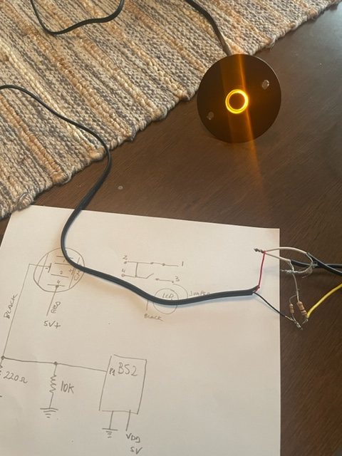
Thanks a lot again!
Yeah, I almost forgot you can eliminate the 10K resistor and put a 100 or 220 ohm in series on the line that goes into the Bs2 pin. I'm driving the Led to 15-20 Ma. you could use a 470 ohm to drop the current to 10 Ma., maybe slightly dimmer. Anyway this was a simple low cost solution. When the button is open the 220 Ohm pulls the pin low to 0 volt, when the button is on with the Led lit, the pin should be at 3.3 volt. I think the Bs2 threshold from low to high is around 1.4 Volt. So total amps., if each led draws 15-20 Ma. that's 20 Ma X 13 = 260 Ma. max. about 1/4 amp.
Do you mind to make a final drawing with the correct values? Please!
Actually, I don't care -- it's your project, not mine. And I never said you'd damage pins; I said the pin limits the amount of current it can sink or source. By using an external buffer, that becomes a non-issue.
You do realize, right, that this is turning your 10K pull-down into a 215-ohm pull-down?
Oh I see. I will replace with a 470 ohm to drop the current to 10 Ma. as @DigitalBob suggested. JonnyMac you help me always with my projects! I really appreciate what you do for us to learn!!!! You are so talented my friend!!!
Thanks a lot!!! God bless you !!!
This is the revised schematic
IMO, you should wire the circuit like this if you only want the LED to light when the button is pressed. This puts the LED circuit and the input circuit in parallel and not in conflict with each other. The 220 is for safety and could be removed -- just don't make that pin you connect to an output-low.
When the button is pressed you will draw 0.5mA plus your LED current.
I will go with this schematic since adding extra wiring is not an option.
Thanks @DigitalBob and @JonnyMac !!!
You need to ensure that the voltage at TP1 when the button is pressed is above the BS2 VIH level (since you're now using the LED and the resistor as a voltage divider).
Deleted
My latest ciruit is good to go. The TP.1 voltage is 3.3V, not 5V+ but plenty. The TTL voltage threshold is 1.4 Volts from low to high and high to low is 0.8V. Its your call just keeping it simple and low cost.
I tested my schematic and works like a champ
This one? see attachment
DigitalBob beat me to it .... see OPTION#3 in Simulation Link below
Luis_P, your latest proposed option won't work... see OPTION #2 in Simulation Link below:
Note: OPTION #1 was the previous option prior to post #56
Simulation Link:
https://tinyurl.com/276o4ero
Confusing. Which one is the option that works? option 3? match the latest schematic by @DigitalBob ? he has a 470K resistor (see picture)
