

Push Button Switch no working
 Luis_P
Posts: 246
Luis_P
Posts: 246
Hello! I have a project to detect a button press with BS2. But the button I need to use is more like a switch. When someone push the button, lights up and remains 'close' until you push again. So basically a switch with a LED (see picture). My BS2 code has a loop to check the state of the pin, LOW or HIGH. I have the typical pull down resistor circuit for button press according to BS2 manual.
My problem is the circuit is working but the LED started flashing until died. I'm using 5V 1.5A power supply. I noticed 3V worked well but I cant power up the BS2 with 3Volts. Any suggestions?

Comments
Depends on the positive voltage applied to the switch. If 5v or less then certainly no problem.
If higher then add a series resistor to protect your io pin. Value will depend on the voltage, and might impact the other pulldown so consider placement.
I’m only using 5V, the voltage supply to the BS2. No more than that…
Using the BS2, and a 5 volt logic, with the 220 Ohm resistor, you should only draw 22 Ma amps. max.. If your going to use the LED you have to think about the 110 volt driving power to light it. Unless it has a dropping resistor you could vary.
If 5v then yoù are fine with the bs2 pulldown example circuit. For powering the led you surely will require a resistor though. 1k is typically a safe value, but to adjust brightness of the led then adjust your resistor value whilst considering the max current of the io pin.
Edit. Great, Bob mentioned the max ma above! You could use a general online "led resistor calculator" to check your current vs resistor is safe.
I have no idea how Im going to light up the button. Any ideas? I only have 5 volts on the BS2…
Deleted
I'm on mobile but you could follow any generic circuit like this:
https://www.instructables.com/Simple-Basic-LED-Circuit-How-to-Use-LEDs/
Obviously youd need the schematic or pinout of your switch to fill in the blanks.
looks like the button you listed takes 110V to light up the Led (must have an internal resistor). Most of those Amazon switches are like that. I would by the ones that have a 3-6 Volt Led.
I tend to stay away from components without a real MFG# or part number. That said, there is this number B01GPLFV60, but it didn't result in very many hits.
Amazon Link:
https://www.amazon.com/Baomain-Button-Switch-Latching-terminal/dp/B01GPLFV60
Here is a schematic from Amazon's site that might help....
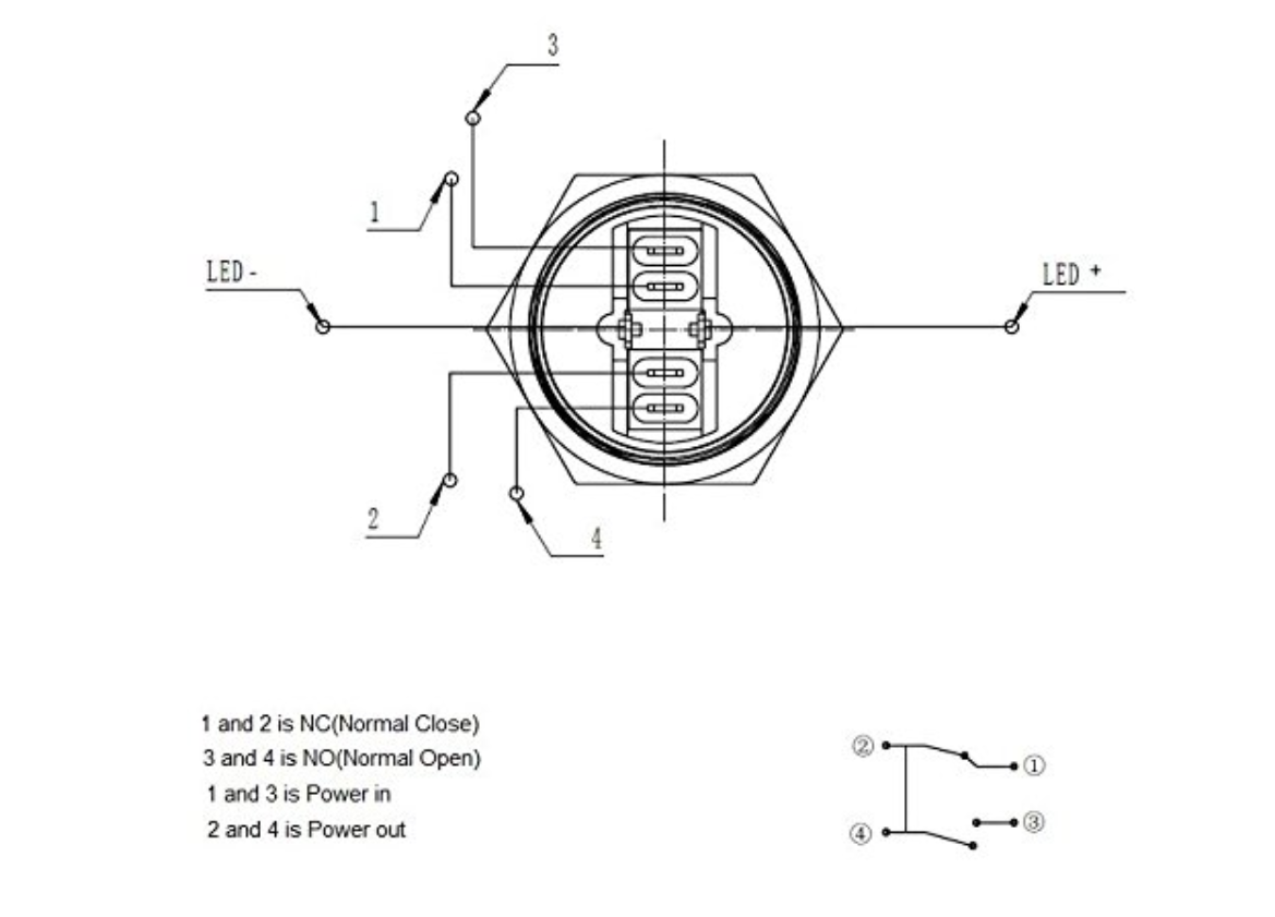
Based on Beau's diagram, seems you could connect the LED+ pin directly to 5V via a 1K series resistor. Then connect LED- to 3, and connect pin 4 to GND.
That gets the LED turning on when the button is pressed.
Then for the signal to the Basic Stamp use the other two pins, 1 and 2.
2 could connect to GND, then pin 1 to your Basic Stamp IO pin. Add a pullup resistor from pin 1 to 5V (10K would be fine). Then read the IO pin state as the button is pressed and observe the state changing from high to low as you operate the button.
My problem is that the circuit is working but the LED started flashing until died. I'm using 5V 1.5A power supply. I noticed 3V worked well but I cant power up the BS2 with 3Volts. Any suggestions? The circuit Im using is in the picture attached.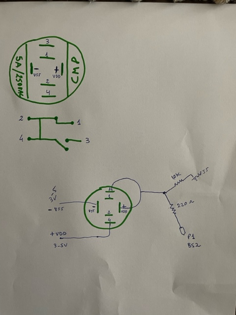
Are you able to measure for continuity between 2 and 4 on the switch ? (Disconnect all wires from the switch first!)
Are 2 and 4 connected with the switch in either the on or off position ?
Also- your wiring seems different to what I mentioned earlier. I would suggest you re-check that what you have created is able to fulfil the needs.
As I understood you wanted 2 things...
1. Toggle the LED on/off as the switch is turned on/off
2. Toggle the BS2 pin state high/low as the switch is turned on/off
I'm not sure your current circuit achieves that. I think you'd want the LED on pins 3 and 4, and the BStamp on pins 1 and 2 ?
The circuit works for the BS2 to detect High/Low when I press the button, no problem with that. The problem is that LED flash red and the died. I’m using 5V. I don’t have the exact part number of the switch, maybe I don’t have the right data sheet and the voltage is 3V instead. I will try to step down the voltage and see what happens.
You might need to verify the button pinout is what you expect.
As it seems now, you have 5V on one side of the LED, and the other side connected to GND via a 10K resistor (ie. LED barely visible), AND also connected to your IO pin via a 220ohm resistor (ie. LED very bright whilst the IO pin is low assuming 5V supplied to the LED). You are not seemingly using the switch mechanism to control the LED, which is perhaps what you intend.
Things we don't know include the exact wiring inside that switch, the specs of the LED (mainly voltage forward is interesting), and if there are any internal resistors in that switch - perhaps in series with the LED (should show up on the wiring info). You could measure these things carefully with a multimeter if there is no datasheet. OR just make some more experiments to figure out what the switch and LED are doing.
One thing is for certain though... using 3V vs 5V won't be an issue for the LED, provided you have an appropriately sized series resistor. Calculating that will depend on factors currently unknown it seems, as mentioned above. Tricky") . Though for testing, 1K is typically a safe value.
. Though for testing, 1K is typically a safe value.
@VonSzarvas @"Beau Schwabe"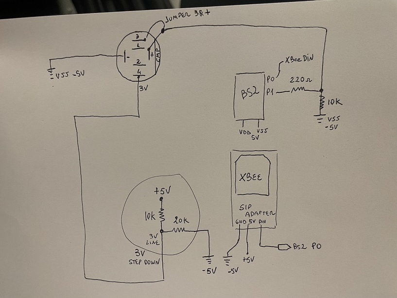
The circuit attached works with some issues with the LED lightness. Bs2 can see when VDD gets to the pin (P1), because pushing the button causes pin 3 on the switch to go high. Because the LED works with 3 volts only, I put 2 resistors in series to step down voltage from 5V to ~3V. Everything works fine but the LED is weak. Do I need more Amperes on my power supply? I'm going to need 13 buttons connected to the Bs2. Yes! 13 buttons. I'm wondering if I need the resistors in series for each button or not?
Run the 5 volt to switch pin 4, run the Bs2 pin with the 220 ohm and 10k resistor to switch pin 1. Remove the jumper between switch pin 3 and led + and replace it with a 220 ohm resistor. Change the logic in your BS2 program that when Bs2 pins are high the button are off.
Replacing the jumper for a 220 ohm resistor what it does ? Remember this button doesn’t like anything higher than 3 volts. Thanks for your help you are awesome!
That will limit the current to light the LED. Remember the only connections you need on switch pins 3 and LED+ are the resistor. You don't need the step down voltage divider. You can try a 1K at first, if the LED doesn't light or is too dim, you can drop the resistance to 500 ohm, 220 ohm, 100 ohm, etc.. Sounds like the switch LED has a built in resistor to work at 3.3V. A bare LED would require 1.6V-2.2V to light it, anything higher without a current limiting resistor will burn it out. So 5V, bare LED, 220 OHM is a good current limit resistor.
Excellent! I power up the button with a 220 ohms and lights up nicely . When I hook all together with the BS2 the light is weak. All works with your suggestion. I just need to figure out how to light the LED better when connected to PIN 1 on the BS2. Change the value of resistor? Use a power supply with more Amperes?
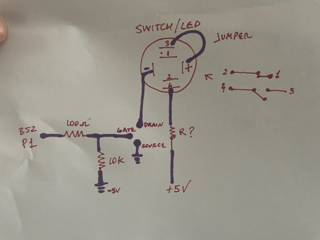
Current from the pin is limited and you don't want to drive a pin too hard. A simple solution is to use a 2N7000 NFET. Connect the Gate to the pin (a 10k pull-down is a good idea, too), the Source to ground, the Drain to the cathode of the LED. Now you can use a a higher source voltage for the LED if you want, and select the resistor for the LED that gives the desired brightness.
Could the unused poles of the switch be used to switch the LED on and off with a single series resistor to the 5V supply. Surely that would be the simplest approach? No need to be concerned about io pin current limits when the LED is not connected to the io pins!
That limits the utility of the LED to showing the button press state. What if you wanted to turn on the LED when the button is pressed, but turn it off with another condition (perhaps a message through the radio).
True, but that didn't seem to be the OP requirement.
Anyway- glad to see that things got worked out. Lots of good advice in this thread.
My first guess is, don't use your step down, power the switch with your 5V, 1.5 amp supply to switch pins 2 and 4. When the switch is off you'll feed the Bs2 pins 220 ohm resistor with maybe 10-20 milliamp max.. When the switch is pressed the BS2 pin will turn off and you'll feed the LED with the 10-20 milliamp, depends on your LED'S foward voltage and current limiting resistor, such as the 220 Ohm. Remember you'll have to multiply the 20 millamps by the number of switches, should they be activated all at the same time. 20 Ma X 30 switch led = 600 milliamp.
This buttons are in a movie theater already installed in the seats and also already wired that way. Adding more wired or reconfigured the connections is a lot of extra work. I will try JonnyMac‘s suggestion. Hopefully that works. Thanks a lot!
JonnyMac please look at my attachment. Is that correct? that's what should I do? I can't change the wiring on the Switch/LED its has 2 wires (- and 4) and a jumper ( 3 to +) when the button is pressed, the +Voltage connected to 4 gets to + pin. Is my drawing correct?
You're indicating -5V where ground should be. Do you have -5v and +5v in your system?
Your drawing of the JonnyMac circuit is wrong. Switch LED+, with resistor goes to your 5V, the R1,100 ohm goes to switch pin 3. Not the BS2.
No. It just ground (the negative from the 5V power supply) > @JonnyMac said: